CN201325894Y - Oily waste water processing device for recovering oil - Google Patents
Oily waste water processing device for recovering oil Download PDFInfo
- Publication number
- CN201325894Y CN201325894Y CNU2008202305023U CN200820230502U CN201325894Y CN 201325894 Y CN201325894 Y CN 201325894Y CN U2008202305023 U CNU2008202305023 U CN U2008202305023U CN 200820230502 U CN200820230502 U CN 200820230502U CN 201325894 Y CN201325894 Y CN 201325894Y
- Authority
- CN
- China
- Prior art keywords
- plate
- oil
- dividing plate
- clapboard
- chamber
- Prior art date
- Legal status (The legal status is an assumption and is not a legal conclusion. Google has not performed a legal analysis and makes no representation as to the accuracy of the status listed.)
- Expired - Lifetime
Links
Images


Abstract
The utility model relates to a water processing device, in particular to an oily waste water processing device for recovering oil, which is characterized by comprising a box, a box cover plate, a first clapboard, a second clapboard, a sealing plate, a third clapboard, a fourth clapboard, and a water outlet tube; the first clapboard, the second clapboard, the third clapboard and the fourth clapboard are connected in sequence from left to right in the hollow cavity of the box; the space between the first clapboard and the left side panel of the box is a first-grade separation chamber; the space between the first clapboard and the second clapboard is divided into an oil storage chamber and a water passing chamber by the sealing plate; the space between the third clapboard and the second clapboard is a second-grade separation chamber; the space between the fourth clapboard and the third clapboard is a water level adjusting chamber; and the space between the fourth clapboard and the right panel of the box is a water purifying chamber. The oily waste water processing device has the advantages of compact and reasonable structure, good oil-water separation effect, high efficiency, small occupying area, convenient and quick cleaning and maintenance, and low running cost. Moreover, the oily waste water processing device can automatically drain water and oil and the running conditions of the device can be monitored electronically in real time.
Description
Technical field
The utility model relates to a kind of water treatment device, is specifically related to the device that a kind of oily(waste)water is handled refiltered oil.
Technical background
Along with the rapid growth of Chinese national economy and the raising of living standards of the people, the quantity of enterprises such as food and drink and food-processing and scale are enlarged rapidly, and they are on the rise to the influence of environment.At present, contain a large amount of animal oil and vegetables oil composition in the sewage that the numerous food and drink of China and food processing enterprises are discharged, except that minority was utilized, the overwhelming majority directly entered in the rivers by water drain, not only severe contamination ecotope, and cause the loss and the waste of oil resource.Present stage is applicable to that the equipment that the food and beverage enterprise oily(waste)water is handled with recovery of oil also lacks, and using more is parallel flow intercepter, these functions of the equipments are single, can not effectively remove solid residue in the waste water, only can tentatively exclude the grease in the water, oil-water separation is poor, and floor space is big.
Summary of the invention
The purpose of this utility model is to provide a kind of oily(waste)water to handle the device of refiltered oil, and this device oil-water separation is good.
To achieve these goals, the technical solution of the utility model is: a kind of oily(waste)water is handled the device of refiltered oil, it is characterized in that it comprise casing, box cover, first dividing plate, second partition, sealing plate, the 3rd dividing plate, the 4th dividing plate, rising pipe; In the casing is cavity, and box cover is arranged on the upper surface of casing; The Left-Hand Panel top of casing is provided with the mouth of a river, and the right panel of casing is provided with rising pipe; First dividing plate, second partition, the 3rd dividing plate, the 4th dividing plate from left to right have been fixedly connected sequentially in the cavity of casing; Space between the Left-Hand Panel of first dividing plate and casing is the flash trapping stage chamber; Fixedly connected a sealing plate between first dividing plate and the second partition, sealing plate is accumulator with the separated by spaces between first dividing plate and the second partition and crosses hydroecium, the front portion of hydroecium between first dividing plate and second partition crossed at the rear portion of accumulator between first dividing plate and second partition; Space between the 3rd dividing plate and the second partition is the secondary separate chamber; Space between the 4th dividing plate and the 3rd dividing plate is the regulation of level chamber; Space between the right panel of the 4th dividing plate and casing is a water purifying chamber; First breach is left in the first dividing plate forward bottom, and first breach is connected the flash trapping stage chamber with the mistake hydroecium; Second breach is left in second partition forward upper end, and second breach will be crossed hydroecium and be connected with the secondary separate chamber; Leave the space between the lower end of the 3rd dividing plate and the bottom surface of casing, the space is connected the secondary separate chamber with the regulation of level chamber; The top of the 4th dividing plate is provided with the regulation of level mouth, and the regulation of level mouth is connected the regulation of level chamber with water purifying chamber; Rising pipe is connected with water purifying chamber; The top at the first dividing plate rear portion is provided with the second adjustable height oil spilling mouth, and the second adjustable height oil spilling mouth is connected the flash trapping stage chamber with accumulator; The top at second partition rear portion is provided with the 3rd adjustable height oil spilling mouth, and the 3rd adjustable height oil spilling mouth is connected the secondary separate chamber with accumulator.
The beneficial effects of the utility model are:
1) adopt flash trapping stage chamber, secondary separate chamber, carry out profit and separate for 2 times, this device oil-water separation is good.
2) by deslagging device is set the most of solid impurity in the oil-water mixture is excluded, the grease solid impurity content that is reclaimed is significantly reduced, only need back and forth pull handle just can realize the compression and the discharge of screen cloth cleaning and solid slag, cleaning is with easy to maintenance, quick.
3) divide oily member by in the flash trapping stage chamber current stabilization being set, the secondary separate chamber is provided with the coalescent member of oil-collecting and has effectively improved oil-water separation.
4) but the real-time monitoring equipment working order convenient is in time cleared up maintenance.
5) structure is provided with compact and reasonable, and floor space is little, and operation and maintenance cost is low.
The utility model is applicable in the industries such as hotel, restaurant, food processing plant residue in the oily(waste)water separated and excludes, and grease in the water is recycled.
Description of drawings
Fig. 1 is structural representation of the present utility model (removes box cover after analyse and observe);
Fig. 2 is the sectional view of deslagging device of the present utility model;
Fig. 3 is the structure diagram that current stabilization of the present utility model divides oily member;
Fig. 4 is the structure diagram of the coalescent member of oil-collecting of the present utility model;
Fig. 5 is the enlarged view of support snap close of the present utility model;
Fig. 6 is the structural representation of one of waved plate of the present utility model;
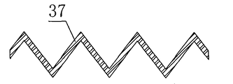
Fig. 7 is two a structural representation of waved plate of the present utility model;
Among the figure: 1-casing, 2-water inlet pipe, 3-deslagging device, 4-flash trapping stage chamber, the driven scraper plate of 5-, 6-is scraper plate initiatively, 7-horizontally-guided positioning strip, 8-push-pull rod, 9-slag notch, 10-secondary separate chamber, 11-" U " type filters cell body, 12-accumulator, the 13-mouth of a river, 14-floats the foam baffle plate, the 15-first adjustable height oil spilling mouth, 16-sediment baffle plate, 17-first dividing plate, the 18-second adjustable height oil spilling mouth, the 19-second partition, the 20-sealing plate, 21-crosses hydroecium, the 22-instrument bin, 23-" L " type oil collection plate, 24-regulation of level chamber, 25-the 3rd dividing plate, 26-shelf, 27-water purifying chamber, 28-the 4th dividing plate, 29-regulation of level mouth, 30-rising pipe, the 31-current stabilization divides oily member, 32-first handle, 33-splash pan, 34-parallel baffle group, the coalescent member of 35-oil-collecting, 36-second handle, the 37-waved plate, 38-supports snap close, 39-the 3rd adjustable height oil spilling mouth, 40-filter opening, 41-slip bucket.Arrow among the figure is represented the flow direction of water.
Embodiment
Below in conjunction with accompanying drawing the utility model preferred version is described; It is included within the scope of the utility model protection, but does not limit the utility model.
As shown in Figure 1, a kind of oily(waste)water is handled the device of refiltered oil, it is characterized in that it comprises casing 1, box cover, deslagging device 3, floating foam baffle plate 14, sediment baffle plate 16, first dividing plate 17, second partition 19, sealing plate 20, " L " type oil collection plate 23, the 3rd dividing plate 25, the 4th dividing plate 28, rising pipe 30; In the casing 1 is cavity, and box cover is arranged on the upper surface of casing 1; The Left-Hand Panel top of casing 1 is provided with the mouth of a river 13, and (left side among Fig. 1 is a left side, and the right is right; Before towards onlooker end being, paper the inner be afterwards), the right panel of casing 1 is provided with rising pipe 30 (breaking siphon outlet piping); Be fixedly connected sequentially from left to right in the cavity of casing 1 (as welding) first dividing plate 17, second partition 19, the 3rd dividing plate 25, the 4th dividing plate 28 are arranged; Space between the Left-Hand Panel of first dividing plate 17 and casing 1 is flash trapping stage chamber 4; Fixedly connected a sealing plate 20 between first dividing plate 17 and the second partition 19, sealing plate 20 is accumulator 12 with the separated by spaces between first dividing plate 17 and the second partition 19 and crosses hydroecium 21, the front portion of hydroecium 21 between first dividing plate 17 and second partition 19 crossed at the rear portion of accumulator 12 between first dividing plate 17 and second partition 19; Space between the 3rd dividing plate 25 and the second partition 19 is secondary separate chamber 10; Space between the 4th dividing plate 28 and the 3rd dividing plate 25 is regulation of level chamber 24; Space between the right panel of the 4th dividing plate 28 and casing 1 is a water purifying chamber 27; First breach is left in first dividing plate, 17 forward bottoms, and first breach is connected flash trapping stage chamber 4 with mistake hydroecium 21; Second breach is left in second partition 19 forward upper ends, and second breach will be crossed hydroecium 21 and be connected with secondary separate chamber 10; Leave the space between the bottom surface of the lower end of the 3rd dividing plate 25 and casing 1, the space is connected secondary separate chamber 10 with regulation of level chamber 24; The top of the 4th dividing plate 28 is provided with regulation of level mouth 29, and regulation of level mouth 29 is connected regulation of level chamber 24 with water purifying chamber 27; Rising pipe 30 is connected with water purifying chamber 27; The top at first dividing plate, 17 rear portions is provided with the second adjustable height oil spilling mouth, 18, the second adjustable height oil spilling mouths 18 flash trapping stage chamber 4 is connected with accumulator 12; The top at second partition 19 rear portions is provided with the 3rd adjustable height oil spilling mouth 39, the three adjustable height oil spilling mouths 39 secondary separate chamber 10 is connected with accumulator 12.
Can realize automatic oil-collecting, oil extraction and draining by the upper-lower position of the difference second adjustable height oil spilling mouth 18, the 3rd adjustable height oil spilling mouth 39 and regulation of level mouth 29 drop keels.
As shown in Figure 1,13 places, the mouth of a river on the Left-Hand Panel of described casing 1 are provided with deslagging device 3.
As shown in Figure 1 and Figure 2, described deslagging device 3 comprises water inlet pipe 2, driven scraper plate 5, initiatively scraper plate 6, horizontally-guided positioning strip 7, push-pull rod 8, " U " type filter cell body 11, cell body cover plate, slip and struggle against 41; " U " type filters cell body 11 and is fixed on the casing 1; It is U type filter vat that " U " type filters in the cell body 11, driven scraper plate 5, active scraper plate 6 lay respectively in the U type filter vat, driven scraper plate 5 is positioned at the initiatively front side of scraper plate 6, driven scraper plate 5 fits tightly with active scraper plate 6 and " U " type filtration cell body 11 three faces that contact, and driven scraper plate 5, active scraper plate 6 are fixed with the scarfing cinder steel brush respectively in the joint place; Be fixed with horizontally-guided positioning strip 7 respectively in the left and right vertical sides panel of " U " type filtration cell body 11, the side chute mouth of driven scraper plate 5, active scraper plate 6 is inserted in (driven scraper plate 5, active scraper plate 6 can move along horizontally-guided positioning strip 7) on the horizontally-guided positioning strip 7 respectively; The rear end of push-pull rod 8 is passed behind the push-pull rod hole on the driven scraper plate 5 and to be fixedlyed connected (using bolting) with active scraper plate 6, the front end of push-pull rod 8 is provided with the T-shape handle, the push-pull rod 8 of the front side of driven scraper plate 5 is provided with the steady brace of projection, and an end that makes push-pull rod have the T-shape handle can not pass the push-pull rod hole of driven scraper plate 5; External force effect push-pull rod can be free to slide and promote initiatively scraper plate 6 back and forth with push-pull rod 8 swivel motion of coming together in the push-pull rod hole of driven scraper plate 5; The base plate leading section that " U " type filters cell body 11 has slag notch 9, the middle part that " U " type filters the base plate of cell body 11 is evenly distributed with the filter opening 40 that pore size is 2~10mm, the pitch-row of filter opening is 2~15mm, and the shape of filter opening can be round, rectangle or rhombus; The bottom surface that " U " type filters the base plate middle part of cell body 11 is fixed with slide bucket 41, and the outlet of slide bucket 41 is the mouth of a river 13; The upper surface that " U " type filters cell body 11 is provided with the cell body cover plate, and the middle part of cell body cover plate is provided with water inlet pipe 2, and water inlet pipe 2 communicates with the U type filter vat that " U " type filters cell body 11.
As shown in Figure 1 and Figure 2, be provided with floating foam baffle plate 14, sediment baffle plate 16 in the described flash trapping stage chamber 4, sediment baffle plate 16 is positioned at the right side of floating foam baffle plate 14; Floating foam baffle plate 14 upper ends are concordant with casing 1 upper limb, the middle part of floating foam baffle plate 14 is provided with the first adjustable height oil spilling mouth 15, the lower end of floating foam baffle plate 14 unsettled (keeping certain distance) with the bottom of casing, the bottom connection of the lower end of sediment baffle plate 16 and casing 1, the upper end of sediment baffle plate 16 is higher than the lower end 0~20mm (be, the upper end of sediment baffle plate 16 is concordant with the lower end of floating foam baffle plate 14) of floating foam baffle plate 14 at 0 o'clock.
As Fig. 1, shown in Figure 3, be placed with current stabilization between described floating foam baffle plate 14 and the sediment baffle plate 16 and divide oily member 31; Current stabilization divides oily member 31 to be made up of bracing frame, first handle 32, splash pan 33, parallel baffle group 34, and bracing frame is formed (constituting the L type) by bottom panel and right panel, is fixed with parallel baffle group 34 on the bottom panel of bracing frame; Parallel baffle group 34 is made up of the parallel baffle of space, is fixed with first handle 32 on the parallel baffle of rear and front end respectively; The bottom panel left end of bracing frame is fixedly connected with splash pan 33.
As shown in Figure 1, be provided with " L " type oil collection plate 23 in the described secondary separate chamber 10, " L " type oil collection plate 23 is fixedlyed connected with the middle part of the 3rd dividing plate 25, space between " L " type oil collection plate 23 and the 3rd dividing plate 25 is an instrument bin 22, the bottom surface of " L " type oil collection plate 23 diminishes oil-collecting space, 10 top, secondary separate chamber horizontal by 20 °~45 ° angles gradually.
As Fig. 1, shown in Figure 4, the bottom in the described secondary separate chamber 10 is provided with shelf 26, and shelf 26 is fixed on the base plate of casing 1, places the coalescent member 35 of oil-collecting on the shelf 26; The coalescent member 35 of oil-collecting is by waved plate 37 mutual stacked combining, and is connected by supporting snap close 38 between waved plate 37 and the waved plate 37, and the upper end of rear and front end waved plate is fixedly connected with second handle 36 respectively.Waved plate 37 cross sections are the ripple struction of trilateral (as shown in Figure 6), sinusoidal curve (as shown in Figure 7) or cosine curve, the ripple trend is horizontal by 30 °~60 ° angles, around the waved plate and be centered close to the trough place and be evenly distributed with self-supporting snap close 38, stacked layer by layer between the waved plate by self-supporting snap close 38, self-supporting snap close 38 upper ends are provided with boss, the lower end is provided with groove, wherein the shape of boss and groove are complementary, make to insert up and down between two snap closes and agree with, can regulate spacing between two waved plates by regulating the depth of penetration of snap close; The snap close center is provided with aperture and runs through the snap close upper/lower terminal, wherein can penetrate screw rod and be used for fixing stacked waved plate group mutually.
In deslagging device 3, be provided with liquid level switch, in accumulator 12, be provided with fuel level sensor, and in instrument bin 22, be provided with facility switching, liquid level shows and warning PLC system, realizes the real-time monitoring of slagging-off member working order and recovery of oil amount.
Present embodiment separates residue in the oily(waste)water and excludes, and to the operational process that grease in the water recycles be: the sewage of impurity such as the oil-containing that catering industry is produced, slag enters the deslagging device 3 from the water inlet pipe 2 of top, casing 1 left side, sewage at first is subjected to buffering between active scraper plate 6 and the driven scraper plate 5 and the flow velocity reduction, solid impurity such as most slags is held back by filter opening in the sewage, and above filter pocket, heap, oil-water mixture and a part of fine impurities are then passed filter opening and are arrived in the flash trapping stage chamber 4 via the mouth of a river 13.Because effluent flow rate reduces, a part of segregative macrobead oil droplet and floating foam emerge rapidly in the sewage, and collection tires out among the space that floating foam baffle plate 14 left sides and casing surround; Another part then enters current stabilization downwards along floating foam baffle plate 14 and divides in the oily member 31, divided by current stabilization that parallel baffle group 34 is divided into the little thread that one strand is independent of each other in the oily member 31, the sewage fluidised form is further stable, and a part of sediment sinks to current stabilization gradually and divides on oily member 31 bottom surfaces.Oil-water mixture continues upwards to flow along sediment baffle plate 16, and the some of them oil droplet emerges in flow process, accumulates on the water surface between floating foam baffle plate 14 and the dividing plate 17, enters accumulator 12 from the second adjustable height oil spilling mouth 18; Another part upwards flowed into secondary from second breach of crossing hydroecium, second partition 19 again and sent out from chamber 10 after flowing into hydroecium with current along first dividing plate, 17 downward first breach through first dividing plate, 17 belows.A part of oil droplet in the oil-water mixture floats on the water surface of secondary separate chamber, enters accumulator 12 from the 3rd adjustable height oil spilling mouth; The tiny oil droplet of another part enters the coalescent member 35 of oil-collecting with current downwards, profit mixed flow form with the class wave in waved plate 37 flows, be convenient to the tiny oil droplets collision coalescence, again because waved plate 37 surfaces have lipophilic-hydrophobic property, oil droplet is attracted to the waved plate surface and forms one deck oil film, continuous process along with current, oil film is thickeied gradually, form after a certain size oil droplet by oil surface tension, be subjected to buoyancy of oil droplet own and impulsive force effect that oil droplet is come off, on float on secondary separate chamber 10 waters surface and gather together, because the cross section of secondary separate chamber 10 diminishes from top to bottom gradually, make oil layer all concentrate on very little zone on the water surface, the oil reservoir thickening enters accumulator 12 from the 3rd adjustable height oil spilling mouth 39.After the separation of oil-water mixture through the secondary separate chamber, overwhelming majority grease is separated, after isolated water is passed down through the coalescent member 35 of oil-collecting, space through the 3rd dividing plate 25 bottoms enters regulation of level chamber 24, height by regulation of level mouth 29 plates above the 4th dividing plate, and cooperation is adjusted to correct position with the second adjustable height oil spilling mouth 18, the 3rd adjustable height oil spilling mouth 39 in the accumulator 12, the grease that collection is tired out on two separate chamber's waters surface overflows in the accumulator 12 automatically, and water is overflowed into.Sewage after solid slag separation and oily water separation flows in the water purifying chamber 27 at last, and flows out this device from bottom to top from rising pipe 30.Be provided with fuel level sensor in the accumulator 12, can monitor the grease storage capability in real time, when reaching the design reserves soon, fuel level sensor will produce guard signal, and the PLC system will show that the grease storage is full, and sound and light alarm notifies the maintenance personnel to reclaim grease.
Along with constantly pouring in of sewage, the solid impurity that " U " type that is trapped in filters on the cell body 11 can get more and more, collection is tired to be arrived to a certain degree, will make the filter opening major part on three faces of U type filter vat blocked, sewage can not in time pass, U type filter vat median water level rises, when reaching the setting alarm water level, be located at liquid level switch in the deslagging device and will move the generation guard signal, the PLC system will show skim gate fault and sound and light alarm, notify the maintenance personnel to spur T-shape push-pull rod 8 on the deslagging device, driving initiatively, scraper plate 6 scrapes U type filter vat, waste residue is moved to driven scraper plate 5 with active scraper plate 6, and the space diminishes and makes waste residue be squeezed between two scraper plates, when squeeze is filtered frictional force between the cell body 11 greater than driven scraper plate 5 and " U " type, driven scraper plate 5 will along with active scraper plate 6 and clip waste residue together on the filter pocket bottom surface slag notch 9 of driven scraper plate 5 one sides move, when waste residue arrives at slag notch 9, will from slag notch 9, spill, be discharged from the slagging-off member.After waste residue is discharged from fully, the maintenance personnel just can promote T-shape push-pull rod 8, make active scraper plate 6 get back to the home position, driven scraper plate 5 also can be got back to original position under the effect of steady brace on the push-pull rod 8, because two scraper plates moving back and forth at " U " type filter vat, be installed in scarfing cinder steel brush on the scraper plate and then can clean simultaneously filter opening in the filter vat back and forth with water, it is unobstructed that filter opening is managed again.
Claims (10)
1. the device of an oily(waste)water processing refiltered oil is characterized in that it comprises casing (1), box cover, first dividing plate (17), second partition (19), sealing plate (20), the 3rd dividing plate (25), the 4th dividing plate (28), rising pipe (30); In the casing (1) is cavity, and box cover is arranged on the upper surface of casing (1); The Left-Hand Panel top of casing (1) is provided with the mouth of a river (13), and the right panel of casing (1) is provided with rising pipe (30); First dividing plate (17), second partition (19), the 3rd dividing plate (25), the 4th dividing plate (28) from left to right have been fixedly connected sequentially in the cavity of casing (1); Space between the Left-Hand Panel of first dividing plate (17) and casing (1) is flash trapping stage chamber (4); Fixedly connected a sealing plate (20) between first dividing plate (17) and the second partition (19), sealing plate (20) is accumulator (12) with the separated by spaces between first dividing plate (17) and the second partition (19) and crosses hydroecium (21), accumulator (12) is positioned at the rear portion between first dividing plate (17) and the second partition (19), and hydroecium (21) is positioned at the front portion between first dividing plate (17) and the second partition (19) excessively; Space between the 3rd dividing plate (25) and the second partition (19) is secondary separate chamber (10); Space between the 4th dividing plate (28) and the 3rd dividing plate (25) is regulation of level chamber (24); Space between the right panel of the 4th dividing plate (28) and casing (1) is water purifying chamber (27); First breach is left in first dividing plate (17) forward bottom, and first breach is connected flash trapping stage chamber (4) with mistake hydroecium (21); Second breach is left in second partition (19) forward upper end, and second breach will be crossed hydroecium (21) and be connected with secondary separate chamber (10); Leave the space between the bottom surface of the lower end of the 3rd dividing plate (25) and casing (1), the space is connected secondary separate chamber (10) with regulation of level chamber (24); The top of the 4th dividing plate (28) is provided with regulation of level mouth (29), and regulation of level mouth (29) is connected regulation of level chamber (24) with water purifying chamber (27); Rising pipe (30) is connected with water purifying chamber (27); The top at first dividing plate (17) rear portion is provided with the second adjustable height oil spilling mouth (18), and the second adjustable height oil spilling mouth (18) is connected flash trapping stage chamber (4) with accumulator (12); The top at second partition (19) rear portion is provided with the 3rd adjustable height oil spilling mouth (39), and the 3rd adjustable height oil spilling mouth (39) is connected secondary separate chamber (10) with accumulator (12).
2. a kind of oily(waste)water according to claim 1 is handled the device of refiltered oil, and it is characterized in that: deslagging device (3) is located to be provided with in the mouth of a river (13) on the Left-Hand Panel of described casing (1).
3. a kind of oily(waste)water according to claim 2 is handled the device of refiltered oil, it is characterized in that: described deslagging device (3) comprises water inlet pipe (2), driven scraper plate (5), initiatively scraper plate (6), horizontally-guided positioning strip (7), push-pull rod (8), " U " type filter cell body (11), cell body cover plate, slide bucket (41); " U " type filters cell body (11) and is fixed on the casing (1); It is U type filter vat that " U " type filters in the cell body (11), driven scraper plate (5), active scraper plate (6) lay respectively in the U type filter vat, driven scraper plate (5) is positioned at the initiatively front side of scraper plate (6), be fixed with horizontally-guided positioning strip (7) respectively in the left and right vertical sides panel of " U " type filtration cell body (11), the side chute mouth of driven scraper plate (5), active scraper plate (6) is inserted in respectively on the horizontally-guided positioning strip (7); Fixedly connected with active scraper plate (6) after passing push-pull rod hole on the driven scraper plate (5) in the rear end of push-pull rod (8), the front end of push-pull rod (8) is provided with the T-shape handle, and the push-pull rod (8) of the front side of driven scraper plate (5) is provided with the steady brace of projection; The base plate leading section that " U " type filters cell body (11) has slag notch (9), and the middle part that " U " type filters the base plate of cell body (11) is evenly distributed with the filter opening that pore size is 2~10mm (40), and the pitch-row of filter opening is 2~15mm; The bottom surface that " U " type filters the base plate middle part of cell body (11) is fixed with slide bucket (41), and the outlet of slide bucket (41) is the mouth of a river (13); The upper surface that " U " type filters cell body (11) is provided with the cell body cover plate, and the middle part of cell body cover plate is provided with water inlet pipe (2), and water inlet pipe (2) communicates with the U type filter vat that " U " type filters cell body (11).
4. a kind of oily(waste)water according to claim 1 is handled the device of refiltered oil, it is characterized in that: be provided with floating foam baffle plate (14), sediment baffle plate (16) in the described flash trapping stage chamber (4), sediment baffle plate (16) is positioned at the right side of floating foam baffle plate (14); Floating foam baffle plate (14) upper end is concordant with casing (1) upper limb, the middle part of floating foam baffle plate (14) is provided with the first adjustable height oil spilling mouth (15), the lower end of floating foam baffle plate (14) is unsettled, the bottom connection of the lower end of sediment baffle plate (16) and casing (1), the upper end of sediment baffle plate (16) are higher than the lower end 0~20mm of floating foam baffle plate (14).
5. a kind of oily(waste)water according to claim 4 is handled the device of refiltered oil, it is characterized in that: be placed with current stabilization between described floating foam baffle plate (14) and the sediment baffle plate (16) and divide oily member (31); Current stabilization divides oily member (31) to be made up of bracing frame, first handle (32), splash pan (33), parallel baffle group (34), and bracing frame is made up of bottom panel and right panel, is fixed with parallel baffle group (34) on the bottom panel of bracing frame; Parallel baffle group (34) is made up of the parallel baffle of space, is fixed with first handle (32) on the parallel baffle of rear and front end respectively; The bottom panel left end of bracing frame is fixedly connected with splash pan (33).
6. a kind of oily(waste)water according to claim 1 is handled the device of refiltered oil, it is characterized in that: be provided with " L " type oil collection plate (23) in the described secondary separate chamber (10), " L " type oil collection plate (23) is fixedlyed connected with the middle part of the 3rd dividing plate (25), space between " L " type oil collection plate (23) and the 3rd dividing plate (25) is instrument bin (22), and the bottom surface of " L " type oil collection plate (23) is horizontal by 20 °~45 ° angles.
7. a kind of oily(waste)water according to claim 1 is handled the device of refiltered oil, it is characterized in that: the bottom in the described secondary separate chamber (10) is provided with shelf (26), shelf (26) is fixed on the base plate of casing (1), and shelf (26) is gone up and placed the coalescent member of oil-collecting (35); The coalescent member of oil-collecting (35) is by mutual stacked the combining of waved plate (37), is connected by support snap close (38) between waved plate (37) and the waved plate (37), and the upper end of rear and front end waved plate is fixedly connected with second handle (36) respectively.
8. according to the device of claim 2 or 3 described a kind of oily(waste)waters processing refiltered oils, it is characterized in that: deslagging device is provided with liquid level switch in (3).
9. a kind of oily(waste)water according to claim 1 is handled the device of refiltered oil, and it is characterized in that: accumulator is provided with fuel level sensor in (12).
10. a kind of oily(waste)water according to claim 6 is handled the device of refiltered oil, it is characterized in that: be provided with facility switching, liquid level demonstration and warning PLC system in the instrument bin (22).
Priority Applications (1)
| Application Number | Priority Date | Filing Date | Title |
|---|---|---|---|
| CNU2008202305023U CN201325894Y (en) | 2008-12-23 | 2008-12-23 | Oily waste water processing device for recovering oil |
Applications Claiming Priority (1)
| Application Number | Priority Date | Filing Date | Title |
|---|---|---|---|
| CNU2008202305023U CN201325894Y (en) | 2008-12-23 | 2008-12-23 | Oily waste water processing device for recovering oil |
Publications (1)
| Publication Number | Publication Date |
|---|---|
| CN201325894Y true CN201325894Y (en) | 2009-10-14 |
Family
ID=41177870
Family Applications (1)
| Application Number | Title | Priority Date | Filing Date |
|---|---|---|---|
| CNU2008202305023U Expired - Lifetime CN201325894Y (en) | 2008-12-23 | 2008-12-23 | Oily waste water processing device for recovering oil |
Country Status (1)
| Country | Link |
|---|---|
| CN (1) | CN201325894Y (en) |
Cited By (15)
| Publication number | Priority date | Publication date | Assignee | Title |
|---|---|---|---|---|
| CN102659213A (en) * | 2012-05-15 | 2012-09-12 | 泰山医学院 | Method and device for removing floating oil and settled sand in waste water based on special type liquid level measuring apparatus |
| CN102992450A (en) * | 2012-12-11 | 2013-03-27 | 昆明金泽实业有限公司 | Diversion-type high-efficient oil separation device |
| CN103084003A (en) * | 2012-12-29 | 2013-05-08 | 苏州韩博厨房电器科技有限公司 | Oil-water separation device of food waste treatment platform |
| CN103787453A (en) * | 2014-02-28 | 2014-05-14 | 甘肃瑞祥环保能源有限公司 | Kitchen oily water collecting device |
| CN104014169A (en) * | 2014-06-26 | 2014-09-03 | 董广星 | Automatic oil-water separating and deslagging device |
| CN104445699A (en) * | 2014-12-25 | 2015-03-25 | 昆明普尔顿环保科技股份有限公司 | Plastic oil separation system |
| CN104828991A (en) * | 2015-05-07 | 2015-08-12 | 中国海洋石油总公司 | Discharging system for offshore platform |
| CN105413241A (en) * | 2015-12-01 | 2016-03-23 | 徐加强 | Digital intelligent oil-water separator capable of remotely monitoring and automatically weighing |
| CN104478153B (en) * | 2014-12-26 | 2016-03-30 | 北京神雾环境能源科技集团股份有限公司 | A kind of oily-water seperating equipment and treatment process processing oily(waste)water |
| CN107362588A (en) * | 2017-09-01 | 2017-11-21 | 黄河水利委员会黄河机械厂 | Portable oil water separator |
| CN108827427A (en) * | 2018-07-19 | 2018-11-16 | 杭州老板电器股份有限公司 | Water-level detecting device and steam box |
| CN109499101A (en) * | 2018-12-17 | 2019-03-22 | 王文生 | A kind of cutting fluid greasy dirt cleaning plant for numerically controlled lathe |
| WO2020076593A1 (en) * | 2018-10-08 | 2020-04-16 | Thermaco, Incorporated | Passive grease trap with double baffle |
| CN114212905A (en) * | 2021-12-18 | 2022-03-22 | 河南油田工程咨询股份有限公司 | Multifunctional oil field pre-water-separation treatment equipment |
| CN114890502A (en) * | 2022-03-25 | 2022-08-12 | 陕西深大通至成投资有限公司 | Oil-water separation device and method for intelligently classifying kitchen waste |
-
2008
- 2008-12-23 CN CNU2008202305023U patent/CN201325894Y/en not_active Expired - Lifetime
Cited By (19)
| Publication number | Priority date | Publication date | Assignee | Title |
|---|---|---|---|---|
| CN102659213A (en) * | 2012-05-15 | 2012-09-12 | 泰山医学院 | Method and device for removing floating oil and settled sand in waste water based on special type liquid level measuring apparatus |
| CN102992450A (en) * | 2012-12-11 | 2013-03-27 | 昆明金泽实业有限公司 | Diversion-type high-efficient oil separation device |
| CN102992450B (en) * | 2012-12-11 | 2014-06-11 | 昆明金泽实业有限公司 | Diversion-type high-efficient oil separation device |
| CN103084003A (en) * | 2012-12-29 | 2013-05-08 | 苏州韩博厨房电器科技有限公司 | Oil-water separation device of food waste treatment platform |
| CN103787453A (en) * | 2014-02-28 | 2014-05-14 | 甘肃瑞祥环保能源有限公司 | Kitchen oily water collecting device |
| CN104014169B (en) * | 2014-06-26 | 2016-01-20 | 董广星 | Water-oil separating automatic deslagging apparatus |
| CN104014169A (en) * | 2014-06-26 | 2014-09-03 | 董广星 | Automatic oil-water separating and deslagging device |
| CN104445699A (en) * | 2014-12-25 | 2015-03-25 | 昆明普尔顿环保科技股份有限公司 | Plastic oil separation system |
| CN104478153B (en) * | 2014-12-26 | 2016-03-30 | 北京神雾环境能源科技集团股份有限公司 | A kind of oily-water seperating equipment and treatment process processing oily(waste)water |
| CN104828991A (en) * | 2015-05-07 | 2015-08-12 | 中国海洋石油总公司 | Discharging system for offshore platform |
| CN105413241A (en) * | 2015-12-01 | 2016-03-23 | 徐加强 | Digital intelligent oil-water separator capable of remotely monitoring and automatically weighing |
| CN107362588A (en) * | 2017-09-01 | 2017-11-21 | 黄河水利委员会黄河机械厂 | Portable oil water separator |
| CN108827427A (en) * | 2018-07-19 | 2018-11-16 | 杭州老板电器股份有限公司 | Water-level detecting device and steam box |
| WO2020076593A1 (en) * | 2018-10-08 | 2020-04-16 | Thermaco, Incorporated | Passive grease trap with double baffle |
| US11040895B2 (en) | 2018-10-08 | 2021-06-22 | Thermaco, Incorporated | Passive grease trap with double baffle |
| CN109499101A (en) * | 2018-12-17 | 2019-03-22 | 王文生 | A kind of cutting fluid greasy dirt cleaning plant for numerically controlled lathe |
| CN109499101B (en) * | 2018-12-17 | 2021-02-12 | 南通科星化工股份有限公司 | Cutting fluid oil stain cleaning device for numerical control lathe |
| CN114212905A (en) * | 2021-12-18 | 2022-03-22 | 河南油田工程咨询股份有限公司 | Multifunctional oil field pre-water-separation treatment equipment |
| CN114890502A (en) * | 2022-03-25 | 2022-08-12 | 陕西深大通至成投资有限公司 | Oil-water separation device and method for intelligently classifying kitchen waste |
Similar Documents
| Publication | Publication Date | Title |
|---|---|---|
| CN201325894Y (en) | Oily waste water processing device for recovering oil | |
| US4400274A (en) | Separator | |
| CN205011428U (en) | Oil isolating pool | |
| US10413848B2 (en) | Scum concentration device | |
| CN209507674U (en) | A kind of oil-isolating device of the decentralized type sewage process tank of suitable rural area | |
| CN200964362Y (en) | High efficiency non-powered oil-water separating device | |
| CN107619122B (en) | Restaurant sewage treatment equipment with oil collecting and backflow device and working method thereof | |
| CN203346194U (en) | Oil separator | |
| CN203048695U (en) | Oil-water separation device for kitchen sewage | |
| CN202529917U (en) | Automatic oil-water separating equipment by filtering and precipitating | |
| CN204400653U (en) | A kind of integration air-float oil eliminator | |
| CN201949687U (en) | Movable oil separation device with built-in heating system for restaurant | |
| CN101544414B (en) | Method and device for treating oily wastewater and recovering oil | |
| CN202864943U (en) | Multifunctional regulating kettle for pretreatment of oily wastewater | |
| CN204097134U (en) | Oily-water seperating equipment | |
| CN201390659Y (en) | Oil collecting and removal device | |
| CN202625897U (en) | Oil-water separation oil insulation tank | |
| CN214653795U (en) | Maintenance-free oil separation tank | |
| CN204897571U (en) | Campus dining room sewage oil interceptor | |
| CN201596381U (en) | Oil removing device | |
| CN201139967Y (en) | Novel environment friendly oil-water separator | |
| CN208071382U (en) | A kind of oil separator | |
| CN201420030Y (en) | Oil-water separating device for processing oil-containing waste water | |
| CN204588763U (en) | A kind of oil partiting precipitation pool | |
| CN209276301U (en) | A kind of oil water separator |
Legal Events
| Date | Code | Title | Description |
|---|---|---|---|
| C14 | Grant of patent or utility model | ||
| GR01 | Patent grant | ||
| CX01 | Expiry of patent term | ||
| CX01 | Expiry of patent term |
Granted publication date: 20091014 |