CN201311129Y - Heat pump air-conditioning system - Google Patents
Heat pump air-conditioning system Download PDFInfo
- Publication number
- CN201311129Y CN201311129Y CNU2008201668458U CN200820166845U CN201311129Y CN 201311129 Y CN201311129 Y CN 201311129Y CN U2008201668458 U CNU2008201668458 U CN U2008201668458U CN 200820166845 U CN200820166845 U CN 200820166845U CN 201311129 Y CN201311129 Y CN 201311129Y
- Authority
- CN
- China
- Prior art keywords
- refrigeration
- heat
- gas
- heat pump
- liquid separator
- Prior art date
- Legal status (The legal status is an assumption and is not a legal conclusion. Google has not performed a legal analysis and makes no representation as to the accuracy of the status listed.)
- Expired - Lifetime
Links
Images


Abstract
The utility model discloses a heat pump air-conditioning system, which comprises a compressor, an evaporating system, a condenser, a four-way change-over valve and a gas-liquid separator, wherein the condenser and the evaporating system are communicated through a refrigerating and heat-production exchange pipe, the evaporating system comprises a high-temperature evaporator and a low-temperature evaporator which are mutually connected in series, wherein the inlet end of the high-temperature evaporator is connected with the refrigerating and heat-production exchange pipe, a gas-liquid separator I is arranged between the high-temperature evaporator and the low-temperature evaporator, a refrigerating throttle valve II is arranged between the gas-liquid separator I and the low-temperature evaporator, a heating one-way valve is connected on the refrigerating throttle valve II in parallel, the air outlet of the gas-liquid separator I is connected with an injector, a suction inlet of the injector is connected with a refrigerating outlet end of the low-temperature evaporator, and the outlet of the injector is communicated with the gas-liquid separator through the four-way change-over valve. The heat pump air-conditioning system can greatly improve the refrigerating property of a heat pump, improves indoor air processing quality, saves energy source, and is more economic and environment-friendly.
Description
Technical field
The utility model relates to field of heating ventilation air conditioning, is specifically related to a kind of heat pump type air conditioning system.
Background technology
In the Air-conditioning Engineering, indoor temperature and humidity are two important parameters that influence thermal comfort, need control.Main method cooling, the dehumidifying of adopting cooling in the present Air-conditioning Engineering.Dedicated outdoor air system is HVAC new technology that development is very fast in recent years.Because in the comfort air conditioning system, sensible heat accounts for the main part of load usually, and latent heat (humidity load) occupies the minority.By hot humidity load is handled respectively, evaporating temperature can improve during refrigeration machine work, thereby efficient is improved, humidity load then can be born by the new wind of handling to low water capacity, surplus wet the time in the decontamination chamber, also guaranteed the ventilation in house, improved indoor air quality.
Heat pump is a kind of hot machine of contrary periodic duty, and the heat that is several times as much as the input energy is emitted in the high-grade energy input that it can be less from the low temperature environment heat absorption and to hot environment.Its low temperature environment can be air, soil, water etc.Heat pump can be used as cooling or firing equipment, is used for as housing heating, air-conditioning, and the drying of material, heating or cooling etc.Developing rapidly along with China's economic society in recent years, the resident living level improves constantly, requirement to the living environment comfortableness also improves constantly thereupon, thereby heat pump with functions such as air-conditioning, heat supplies, air source heat pump particularly, with its cheapness easily characteristics obtained widely to use, and estimate development, its production and use and also will continue to enlarge along with economic society.But thermodynamic principles have determined the heat source temperature influence of will catching a cold of heat pump its performance of when work, air source heat pump is its Cooling and Heat Source with extraneous surrounding air, its performance is influenced by ambient temperature not only, also relevant with its temperature levels to the Cooling and Heat Source of indoor terminal output, and the influence of environment temperature and heat supply, air conditioner load variation tendency are opposite: winter, temperature reduces, the premises heating load increases, but the heat pump heating capacity then descends with temperature, degradation, when temperature drops to a certain degree, conventional air source heat pump even cisco unity malfunction; In summer, temperature raises, and air conditioner load increases, but the heat pump refrigerating ability then raises with temperature and descend, and performance is variation also.
In addition, present heat pump techniques, indoor use side mainly adopts the heat convection mode, during the summer air-conditioning refrigeration, for keeping and control indoor temperature and humidity, the employing type of cooling is room temperature lowering, dehumidifying, make it be in human thermal comfort zone, this certainly will will reduce the thermo-compression evaporation temperature, thereby influences heat pump performance, and the condensate water that cooling and dehumidifying produces also brings problem of indoor air quality, influences people's health; During winter heating, the wind pushing temperature that satisfies human thermal comfort sense requirement can not be too low, thereby require heat pump will keep higher condensation temperature and pressure, and this also can reduce its heating performance.Further improve heat pump performance, except that continuing deeply to carry out being necessary to seek new technique direction the aforementioned research.
The utility model content
The utility model the technical problem that will just solve just provide a kind of heat pump type air conditioning system, the refrigeration and the heating performance of the raising heat pump that it can be bigger improve the quality that room air is handled, and save the energy, environmental protection more economically.
In order to solve the problems of the technologies described above, the utility model adopts following technical scheme: a kind of heat pump type air conditioning system, comprise compressor, vapo(u)rization system, condenser, four-way change-over valve, be provided with gas-liquid separator between described compressor return air mouth and four-way change-over valve, described condenser and vapo(u)rization system be the gas outlet UNICOM by four-way change-over valve and compressor respectively, pass through refrigeration between condenser and vapo(u)rization system, heat exchange pipeline UNICOM, it is characterized in that: described vapo(u)rization system comprises the high-temperature evaporator and the cryogenic vaporizer of mutual serial connection, the high-temperature evaporator arrival end connects refrigeration, heat the exchange pipeline, be provided with gas-liquid separator one between described high-temperature evaporator and the cryogenic vaporizer, be provided with refrigeration choke valve two between gas-liquid separator one and the cryogenic vaporizer, be parallel with one on the refrigeration choke valve two and heat check valve, described gas-liquid separator one gas outlet is connected with injector, the suction inlet of injector is connected with the cryogenic vaporizer refrigeration port of export, and the outlet of injector is communicated with by four-way change-over valve with gas-liquid separator.
Preferably, described refrigeration, heat the exchange pipeline and comprise the refrigeration branch road one of bridge joint and heat branch road one and be connected refrigeration, heat the liquid reservoir and the device for drying and filtering that exchange on the pipeline, described refrigeration branch road one comprises the refrigeration check valve and the refrigeration choke valve one of mutual serial connection, and the described branch road one that heats comprises heating check valve and heating choke valve of mutual serial connection.
Preferably, described vapo(u)rization system is some groups for being arranged in parallel.
Improved, the choke valve one that independently freezes is set respectively on described every group of vapo(u)rization system, be parallel with on the refrigeration choke valve one and heat check valve, so more be better than independent control to every group of vapo(u)rization system.
The utility model adopts technique scheme, vapo(u)rization system is set to high-temperature evaporator and cryogenic vaporizer, and at cryogenic vaporizer two ends parallel connection one injector, the refrigerant vapour that a part of high-temperature evaporator is produced is as the working gas injection, the refrigerant vapour that the pressurization cryogenic vaporizer produces carries out the throttling of the degree of depth to be handled, so just realize that high-temperature evaporator provides the high temperature low-temperature receiver, handle the air-conditioning sensible heat load, i.e. cooling, cryogenic vaporizer is handled latent heat load, i.e. dehumidifying, thereby the refrigeration performance of bigger raising heat pump improve the quality that room air is handled, save the energy, environmental protection more economically.
Description of drawings
The utility model is described in further detail below in conjunction with accompanying drawing:
Fig. 1 is the utility model heat pump type air conditioning system embodiment one structural representation;
Fig. 2 is the utility model heat pump type air conditioning system embodiment two structural representations for figure;
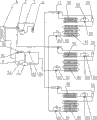
Fig. 3 is the utility model heat pump type air conditioning system embodiment three structural representations for figure.
The specific embodiment
As shown in Figure 1, be a kind of heat pump type air conditioning system embodiment one of the utility model, comprise compressor 1, vapo(u)rization system, condenser 4, four-way change-over valve 2, compressor 1 return-air mouth and 2 of four-way change-over valves are provided with gas-liquid separator 3, described condenser and vapo(u)rization system be the gas outlet UNICOM by four-way change-over valve and compressor respectively, pass through refrigeration between condenser and vapo(u)rization system, heat exchange pipeline 01 UNICOM, described vapo(u)rization system comprises the high-temperature evaporator 91 and the cryogenic vaporizer 92 of mutual serial connection, the high-temperature evaporator arrival end connects refrigeration, heat the exchange pipeline, be provided with gas-liquid separator 1 between described high-temperature evaporator and the cryogenic vaporizer, be provided with refrigeration choke valve 2 63 between gas-liquid separator one and the cryogenic vaporizer, refrigeration is parallel with opposite with its a flow direction check valve 52 that heats on the choke valve 2 63, described gas-liquid separator one 10 gas outlets are connected with injector 11, the suction inlet of injector 11 is connected with the cryogenic vaporizer 92 refrigeration ports of export, and the outlet of injector 11 is communicated with by four-way change-over valve 2 with gas-liquid separator 3.Described refrigeration, heat exchange pipeline 01 and comprise the refrigeration branch road one of bridge joint and heat branch road one and be connected refrigeration, heat the liquid reservoir 7 and the device for drying and filtering 8 that exchange on the pipeline, refrigeration branch road one and heat branch road one and flow to reverse setting, described refrigeration branch road one comprises the refrigeration check valve 51 and the refrigeration choke valve 1 of mutual serial connection, heats branch road one and comprises heating check valve 52 and heating choke valve 62 of mutual serial connection.
As Fig. 2, be the utility model heat pump type air conditioning system embodiment two structural representations, it is on the basis of embodiment one, two groups of being set to be arranged in parallel of described vapo(u)rization system, the choke valve 1 that independently freezes is set respectively on every group of vapo(u)rization system, refrigeration is parallel with opposite with its flow direction check valve 52 that heats on the choke valve 1, so more is better than the independent of every group of vapo(u)rization system controlled.
As Fig. 3, be the utility model heat pump type air conditioning system embodiment three structural representations, on the basis of embodiment one, three groups of being set to be arranged in parallel of described vapo(u)rization system, the choke valve 1 that independently freezes is set respectively on every group of vapo(u)rization system, is parallel with opposite with its flow direction check valve 52 that heats on the refrigeration choke valve 1.
As Fig. 2, under cooling condition, after cold-producing medium is discharged from compressor 1, after four-way change-over valve 2 enters condenser 4 and is condensed into liquid, enter liquid reservoir 7, device for drying and filtering 8, refrigeration check valve 51 through refrigeration check valve 51, again after one 61 throttlings of refrigeration choke valve, enter high-temperature evaporator 91 evaporation heat absorptions, refrigeration, enter vapour liquid separator 1 after becoming liquid-vapor mixture, liquid-vapor mixture is separated into two-phase at this, the working steam that gas enters as injector 11 enters injector, and injection is from the cold-producing medium of cryogenic vaporizer 92; Refrigerant liquid in the vapour liquid separator one enters cryogenic vaporizer 92 heat absorption evaporations after 2 63 throttlings of refrigeration choke valve, injected device 11 injections enter injector after becoming gaseous state, mix, boost after four-way change-over valve 2 enters compressor 1 after entering vapour liquid separator 3 again with working steam, finish a kind of refrigeration cycle.During the heat pump heating operation, after cold-producing medium is discharged from compressor 1, enter injector 11 through four-way change-over valve 2, enter cryogenic vaporizer 92, after the part heat is emitted in condensation, through heating check valve 52, vapour liquid separator 1 enters high-temperature evaporator 91, cold-producing medium is condensed into liquid in high-temperature evaporator after, enter liquid reservoir 7 through heating check valve 52, device for drying and filtering 8, heat check valve 52, after heating choke valve 62 throttlings, enter the condenser heat absorption again, evaporation, become gas after four-way change-over valve 2 enters compressor 1 after entering vapour liquid separator 3 again, finish heating circulation, arrow is depicted as and flows to signal among the figure.
Above-mentioned high-temperature evaporator and cryogenic vaporizer can be various types of heat exchangers, are used for heating or refrigerating mediums such as cooling water, air.
Claims (5)
1, a kind of heat pump type air conditioning system, comprise compressor, vapo(u)rization system, condenser, four-way change-over valve, be provided with gas-liquid separator between described compressor return air mouth and four-way change-over valve, described condenser and vapo(u)rization system be the gas outlet UNICOM by four-way change-over valve and compressor respectively, pass through refrigeration between condenser and vapo(u)rization system, heat exchange pipeline UNICOM, it is characterized in that: described vapo(u)rization system comprises the high-temperature evaporator and the cryogenic vaporizer of mutual serial connection, the high-temperature evaporator arrival end connects refrigeration, heat the exchange pipeline, be provided with gas-liquid separator one between described high-temperature evaporator and the cryogenic vaporizer, be provided with refrigeration choke valve two between gas-liquid separator one and the cryogenic vaporizer, be parallel with one on the refrigeration choke valve two and heat check valve, described gas-liquid separator one gas outlet is connected with injector, the suction inlet of injector is connected with the cryogenic vaporizer refrigeration port of export, and the outlet of injector is communicated with by four-way change-over valve with gas-liquid separator.
2, heat pump type air conditioning system according to claim 1, it is characterized in that: described refrigeration, heat the exchange pipeline comprise the refrigeration branch road one of bridge joint and heat branch road one, described refrigeration branch road one comprises the refrigeration check valve and the refrigeration choke valve one of mutual serial connection, and the described branch road one that heats comprises heating check valve and heating choke valve of mutual serial connection.
3, heat pump type air conditioning system according to claim 2 is characterized in that: described refrigeration, heat the exchange pipeline be provided with liquid reservoir and device for drying and filtering.
4, according to claim 1,2 or 3 described heat pump type air conditioning systems, it is characterized in that: described vapo(u)rization system is some groups that are arranged in parallel.
5, heat pump type air conditioning system according to claim 4 is characterized in that: the choke valve one that independently freezes is set respectively on described every group of vapo(u)rization system, is parallel with on the refrigeration choke valve one and heats check valve.
Priority Applications (1)
| Application Number | Priority Date | Filing Date | Title |
|---|---|---|---|
| CNU2008201668458U CN201311129Y (en) | 2008-10-23 | 2008-10-23 | Heat pump air-conditioning system |
Applications Claiming Priority (1)
| Application Number | Priority Date | Filing Date | Title |
|---|---|---|---|
| CNU2008201668458U CN201311129Y (en) | 2008-10-23 | 2008-10-23 | Heat pump air-conditioning system |
Publications (1)
| Publication Number | Publication Date |
|---|---|
| CN201311129Y true CN201311129Y (en) | 2009-09-16 |
Family
ID=41108384
Family Applications (1)
| Application Number | Title | Priority Date | Filing Date |
|---|---|---|---|
| CNU2008201668458U Expired - Lifetime CN201311129Y (en) | 2008-10-23 | 2008-10-23 | Heat pump air-conditioning system |
Country Status (1)
| Country | Link |
|---|---|
| CN (1) | CN201311129Y (en) |
Cited By (5)
| Publication number | Priority date | Publication date | Assignee | Title |
|---|---|---|---|---|
| CN102141316A (en) * | 2011-03-03 | 2011-08-03 | 清华大学 | Double-evaporation-temperature air conditioner with temperature and humidity controlled independently |
| CN103759468A (en) * | 2014-01-08 | 2014-04-30 | 浙江理工大学 | Heat pump system with dual-temperature heat sources |
| CN103822393A (en) * | 2012-11-16 | 2014-05-28 | 珠海格力电器股份有限公司 | Air-conditioning system |
| CN107144041A (en) * | 2017-06-20 | 2017-09-08 | 重庆鸿佳新科技有限公司 | One kind, which is freezed and heated, uses throttle system |
| CN111023363A (en) * | 2019-12-17 | 2020-04-17 | 海信(山东)空调有限公司 | Air conditioner and control method |
-
2008
- 2008-10-23 CN CNU2008201668458U patent/CN201311129Y/en not_active Expired - Lifetime
Cited By (7)
| Publication number | Priority date | Publication date | Assignee | Title |
|---|---|---|---|---|
| CN102141316A (en) * | 2011-03-03 | 2011-08-03 | 清华大学 | Double-evaporation-temperature air conditioner with temperature and humidity controlled independently |
| CN103822393A (en) * | 2012-11-16 | 2014-05-28 | 珠海格力电器股份有限公司 | Air-conditioning system |
| CN103822393B (en) * | 2012-11-16 | 2016-03-23 | 珠海格力电器股份有限公司 | Air-conditioning system |
| CN103759468A (en) * | 2014-01-08 | 2014-04-30 | 浙江理工大学 | Heat pump system with dual-temperature heat sources |
| CN107144041A (en) * | 2017-06-20 | 2017-09-08 | 重庆鸿佳新科技有限公司 | One kind, which is freezed and heated, uses throttle system |
| CN111023363A (en) * | 2019-12-17 | 2020-04-17 | 海信(山东)空调有限公司 | Air conditioner and control method |
| CN111023363B (en) * | 2019-12-17 | 2021-10-29 | 海信(山东)空调有限公司 | Air conditioner and control method |
Similar Documents
| Publication | Publication Date | Title |
|---|---|---|
| CN101403541B (en) | Heat pump air conditioning system | |
| CN101392969B (en) | Heat pump air conditioning system | |
| CN204665596U (en) | Direct-expansion type heat-recycling air treatment device | |
| CN203132011U (en) | Liquid desiccant regeneration heat-and-humidity independent treatment air-conditioner device | |
| CN106016771A (en) | Solar air source heat pump triple co-generation system and control method thereof | |
| CN103017269A (en) | Solution dehumidification/regeneration heat and moisture independent treatment air conditioning device and energy-saving operation method thereof | |
| CN103196262A (en) | Hot gas bypass defrosting device for air source heat pump water heater | |
| CN102777990B (en) | Air conditioning unit system of water source heat pump in reservoir for underground hydropower station | |
| CN102840716B (en) | Heat pump system and control method thereof | |
| CN201311129Y (en) | Heat pump air-conditioning system | |
| CN101943503B (en) | Air-conditioning refrigeration facility | |
| CN201866989U (en) | Household energy recovery tri-generation unit | |
| CN201787768U (en) | Air conditioning refrigeration device | |
| CN110749018A (en) | Single-machine two-stage compression middle air exhaust heat recovery fresh air processing device | |
| CN202328962U (en) | Water heater system of condensation heat defrosting air conditioner | |
| CN101907372B (en) | Hot-water air conditioning unit | |
| CN103836792A (en) | Heat pump and hot water heating combination system | |
| CN202119162U (en) | Heat pump system | |
| CN101957089A (en) | Refrigerating device of air conditioner and household air conditioning system thereof | |
| CN201748722U (en) | Throttle device of air conditioner | |
| CN203595316U (en) | Screw rod type total heat recovery air-cooled heat pump air conditioning unit | |
| CN107101417A (en) | The preposition mode changes in temperature hot water three-way set of water- to-water heat exchanger four | |
| CN203719237U (en) | Dual-temperature heat source heat pump system | |
| CN102829519A (en) | Dehumidifying unit of double cold source all fresh air heat pump provided with cold carrying heat exchanger | |
| CN201034394Y (en) | Air-conditioning hot pump hot-water machine set |
Legal Events
| Date | Code | Title | Description |
|---|---|---|---|
| C14 | Grant of patent or utility model | ||
| GR01 | Patent grant | ||
| AV01 | Patent right actively abandoned |
Granted publication date: 20090916 Effective date of abandoning: 20081023 |