CN201308943Y - Punching die for flywheel with a plurality of lug bosses - Google Patents
Punching die for flywheel with a plurality of lug bosses Download PDFInfo
- Publication number
- CN201308943Y CN201308943Y CNU2008201009179U CN200820100917U CN201308943Y CN 201308943 Y CN201308943 Y CN 201308943Y CN U2008201009179 U CNU2008201009179 U CN U2008201009179U CN 200820100917 U CN200820100917 U CN 200820100917U CN 201308943 Y CN201308943 Y CN 201308943Y
- Authority
- CN
- China
- Prior art keywords
- drift
- convex closure
- supporting seat
- flywheel
- ratchet
- Prior art date
- Legal status (The legal status is an assumption and is not a legal conclusion. Google has not performed a legal analysis and makes no representation as to the accuracy of the status listed.)
- Expired - Fee Related
Links
Images


Landscapes
- Perforating, Stamping-Out Or Severing By Means Other Than Cutting (AREA)
Abstract
The utility model relates to a punching die for a flywheel with a plurality of lug bosses, comprising an upper die mechanism and a lower die mechanism opposite to each other up and down, wherein the lower die mechanism comprises a support seat fixed on a base. The punching die for the flywheel with a plurality of lug bosses is characterized in that the support seat is a cube with a horizontal through hole arranged in the middle, and a graduated ratchet shaft penetrates through the horizontal through hole; a ratchet wheel is arranged at one end of the graduated ratchet shaft, and a shell positioning disk is fixed at the other end; a graduated limit mechanism is mounted on the rear wall of the support seat to limit the ratchet wheel, a punch supporting mechanism is also sleeved on the graduated ratchet shaft and arranged between the support seat and the shell positioning disk, and a convex punch is fixed on the punch supporting mechanism and is opposite to a concave die orifice of a convex female die. The utility model can effectively prevent a product generating accumulated errors and ensure more rapid and accurate product orientation and product quality. Meanwhile, the utility model reduces repeated manual clamping contraposition frequency, is more convenient to operate, lightens the labor intensity of workers and improves the working efficiency to a great extent.
Description
Technical field
The utility model belongs to the engine magneto and makes equipment, specifically is a kind of many boss flywheel punching out mould of punching press magneto convex closure.
Background technology
As Fig. 1; shown in 2: the diel of existing magneto flywheel convex closure is made up of relative up and down last mold mechanism and following mold mechanism; wherein go up mold mechanism and be provided with the convex closure die; following mold mechanism comprises the supporting seat that is fixed on the base; a semicircle boss that retains semicircle is set on the sidewall of supporting seat; its semi-circular portions is installed and is taken off material rubber and convex closure drift; make the convex closure drift relative with the convex closure die; the magneto flywheel casing is sleeved on semicircle boss; take off on material rubber and the convex closure drift; make shell wall between convex closure drift and convex closure die; descending by hydraulic pressure or the last mold mechanism of decompressor promotion; under the effect of convex closure drift and convex closure die, on the magneto flywheel casing, form the flywheel convex closure.But on flywheel casing, stamp out a plurality of convex closures equably, just flywheel casing repeatedly need be taken off, reinstall again and contraposition, relatively accurate in order to ensure the convex closure contraposition, stripper plate is installed on supporting seat, and on stripper plate, fix a bit block, and will go up a shaping convex closure and be resisted against on the bit block, be convenient to next convex closure contraposition punching press.
The shortcoming of existing flywheel punching out mould: after finishing a punching press, need the artificial magneto casing rotation contraposition of adjusting, carry out convex closure punching press next time again, complex operation step, workman's amount of labour is bigger, and efficient is low, and the dependence of convex closure location is bit block, the cumulative errors of convex closure spacing are bigger, have a strong impact on product quality.
The utility model content
The purpose of this utility model provides a kind of many boss easy to use flywheel punching out mould, after to clamping location of magneto casing, just can carry out repeatedly uninterrupted punching press, step simplifies the operation, reduce workman's amount of labour, increase work efficiency, can also avoid the cumulative errors of convex closure spacing fully, guarantee product quality.
For achieving the above object; a kind of many boss flywheel punching out mould described in the utility model; form by relative up and down last mold mechanism and following mold mechanism; wherein descend mold mechanism to comprise the supporting seat that is fixed on the base; its key is: described supporting seat is the cubic block that the middle part has horizontal through hole; be installed with the index pawl axle in this horizontal through hole; one end of this index pawl axle is a ratchet; the other end is fixed with the housing positioning disk; wherein the ratchet end is positioned at the rear side of described supporting seat; it is spacing to described ratchet that the calibration position-limit mechanism is installed on the rear wall of this supporting seat; described index pawl axle also is set with the drift supporting mechanism; this drift supporting mechanism is between described supporting seat and housing positioning disk; be fixed with the convex closure drift near on the drift supporting mechanism of described housing positioning disk, this convex closure drift is over against the described die mouth of going up mold mechanism convexity bag die.
Magneto casing is fixed on the housing positioning disk.The last mold mechanism of driving mechanism such as hydraulic pressure or punching press promotion moves down with magneto casing and contacts, and drives index pawl axle and ratchet and moves down synchronously, makes magneto casing form convex closure with the groove that the convex closure drift enters the convex closure die; Move on the last mold mechanism, index pawl axle and ratchet return, magneto casing separates with the convex closure drift, and the calibration position-limit mechanism drives ratchet and rotates, and spacing to ratchet.Ratchet rotates a predetermined angular, housing positioning disk and magneto casing are corresponding to turn an angle, get ready for convex closure punching press next time, realized the one-time positioning clamping, the continuous several times punching press, this designs simplification operating procedure, reduced workman's the amount of labour, improved operating efficiency, the convex closure spacing is determined by ratchet gear teeth position, avoid the generation of convex closure spacing cumulative errors fully, guaranteed product quality.
Have notch on the antetheca of described supporting seat, the rear portion of described drift supporting mechanism is positioned at this notch, and described convex closure drift is positioned at the front portion of this drift supporting mechanism.
Liquidate head support mechanism location of antetheca notch.
Described drift supporting mechanism comprises the drift holder, the rear portion of this drift holder is a semi-cylindrical in configuration, this semicolumn is positioned at the notch on the described supporting seat antetheca, the circle centre position fluting of this semicolumn also is equipped with bearing, this bearing holder (housing, cover) is contained on the described index pawl axle, the first half of described bearing is positioned at the semicircle heart groove of described semicolumn, the Lower Half of this bearing is positioned on the semicircle concave surface that is placed on bearing bracket, this bearing bracket is placed on and takes off on the material rubber, this takes off material rubber and is positioned on the described base, on the described base that takes off between material rubber and the drift holder front portion limited block is installed;
The front portion of described drift holder is a column structure, the front end of this cylinder has groove and communicates with the semicircle heart groove of described semicolumn, the drift support ring is installed in this groove, after described index pawl axle passes from the central authorities of this drift support ring, is connected with described housing positioning disk again.
The upper end of described drift support ring is the plane, places described convex closure drift on this plane, and the base of this convex closure drift is positioned on the drift support ring, and the drift of convex closure drift passes from the upper wall of described drift holder front portion.
The cross sectional shape of described horizontal through hole is that the cross sectional shape of vertical bar shape, described drift support ring center through hole is vertical bar shaped.
Described base is provided with lead, and the described mold mechanism of going up has fairlead, and this fairlead is over against described lead.
The index pawl axle drives bearing and bearing bracket moves down, and takes off material rubber and is compressed; Index pawl axle return rotates, and drives bearing element, reduces rolling friction.
When the index pawl axle moved up and down, drift support ring and convex closure drift maintained static.When last mold mechanism moved down, lead entered fairlead, helped the location.
Have vertical through hole in the described supporting seat balancing pole is installed, the lower end of this balancing pole is placed on the described index pawl axle, described supporting seat is stretched out in the upper end of this balancing pole, and the upper end of this balancing pole is equipped with impact head, and this impact head and the described distance that goes up mold mechanism are S;
The described distance that goes up mold mechanism convexity bag die and described convex closure drift top is S ', and the range difference of S and S ' is the thickness of magneto casing, and after the housing positioning disk was installed magneto casing, the distance of convex closure die and magneto casing was S.
Last mold mechanism moves down; the convex closure die contacts with magneto casing; driving index pawl axle front portion through the housing positioning disk moves down; going up simultaneously the mold mechanism rear end contacts with the impact head of balancing pole upper end; driving index pawl axle rear portion through balancing pole moves down; parallel the moving down of part before and after guaranteeing is until convex closure die and the parallel contact of the flywheel casing on the drift.
Described calibration position-limit mechanism is made up of the downward stopper slot in aperture, spring and spacer pin, wherein the upper end of spacer pin is stretched in the stopper slot, described spring is connected between spacer pin upper end and the stopper slot roof, the lower surface of spacer pin is the inclined-plane, described index pawl dog end wheel backlash is stretched in the lower end of this spacer pin, these ratchet gear teeth are the angle tooth, and the lower surface of this angle tooth and described spacer pin matches.
The calibration position-limit mechanism maintains static, and index pawl axle and ratchet move down, and makes the most advanced and sophisticated spacer pin lower end that arrives of the ratchet gear teeth; Retract the position on index pawl axle and the ratchet, the spring compression promotes the spacer pin lower end and slips into ratchet wheel backlash, drives ratchet and rotates gear teeth.
Described housing positioning disk is provided with positioning convex.
Positioning convex is fixed on magneto casing on the housing positioning disk.
Remarkable result of the present utility model is: accurately control the index pawl axle and rotate under same angle, make the spacing between magneto casing two convex closures equate that the convex closure spacing is determined by ratchet gear teeth position, avoided the generation of convex closure spacing cumulative errors, it is more accurate to locate, and guarantees product quality.Reduce artificial participation simultaneously, made more convenient to operately, reduced workman's the amount of labour, improved operating efficiency.
Description of drawings
Fig. 1 is the cut-away view of prior art;
Fig. 2 is the structural representation of the positive side of prior art;
Fig. 3 is a cut-away view of the present utility model;
Fig. 4 is the structural representation of the positive side of the utility model;
Fig. 5 is the structural representation of the utility model rear side.
The specific embodiment
Below in conjunction with the drawings and specific embodiments the utility model is described in further detail.
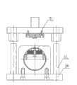
Shown in Fig. 3,4; the utility model provides a kind of many boss flywheel punching out mould; form by relative up and down last mold mechanism and following mold mechanism; wherein go up mold mechanism and be provided with fairlead 2 and convex closure die 21, following mold mechanism comprises supporting seat 3, drift supporting mechanism, convex closure drift 1, index pawl axle 8, ratchet 8a, calibration position-limit mechanism and housing positioning disk 9.
Described supporting seat 3 has the cubic block of horizontal through hole a for the middle part; be installed with index pawl axle 8 among this horizontal through hole a; one end of this index pawl axle 8 is ratchet 8a; the other end is fixed with housing positioning disk 9; wherein ratchet 8a end is positioned at the rear side of described supporting seat 3; it is spacing to described ratchet 8a that the calibration position-limit mechanism is installed on the rear wall of this supporting seat 3; described index pawl axle 8 also is set with the drift supporting mechanism; this drift supporting mechanism is between described supporting seat 3 and housing positioning disk 9; be fixed with convex closure drift 1 near on the drift supporting mechanism of described housing positioning disk 9, this convex closure drift 1 is over against the described die mouth of going up mold mechanism convexity bag die 21.
Have notch on the antetheca of described supporting seat 3, the rear portion of described drift supporting mechanism is positioned at this notch, and described convex closure drift 1 is positioned at the front portion of this drift supporting mechanism.
Described drift supporting mechanism comprises drift holder 6, the rear portion of this drift holder 6 is a semi-cylindrical in configuration, this semicolumn is positioned at the notch on described supporting seat 3 antethecas, the circle centre position fluting of this semicolumn also is equipped with bearing 12, this bearing 12 is sleeved on the described index pawl axle 8, the first half of described bearing 12 is positioned at the semicircle heart groove of described semicolumn, the Lower Half of this bearing 12 is positioned on the semicircle concave surface that is placed on bearing bracket 5, this bearing bracket 5 is placed on and takes off on the material rubber 4, this takes off material rubber 4 and is positioned on the described base 20, on the described base 20 that takes off between material rubber 4 and drift holder 6 front portions limited block 22 is installed;
The front portion of described drift holder 6 is a column structure, the front end of this cylinder has groove and communicates with the semicircle heart groove of described semicolumn, drift support ring 7 is installed in this groove, after described index pawl axle 8 passes from the central authorities of this drift support ring 7, is connected with described housing positioning disk 9 again.
The upper end of described drift support ring 7 is the plane, places described convex closure drift 1 on this plane, and the base of this convex closure drift 1 is positioned on the drift support ring 7, and the drift of convex closure drift 1 passes from the upper wall of described drift holder 6 front portions.
The cross sectional shape of described horizontal through hole a is that the cross sectional shape of vertical bar shape, described drift support ring 7 center through hole is vertical bar shaped.
Described base 20 is provided with lead 11, and the described mold mechanism of going up has fairlead 2, and this fairlead 2 is over against described lead 11.
As shown in Figure 3: have vertical through hole in the described supporting seat 3 balancing pole 16 is installed, the lower end of this balancing pole 16 is placed on the described index pawl axle 8, described supporting seat 3 is stretched out in the upper end of this balancing pole 16, the upper end of this balancing pole 16 is equipped with impact head, and this impact head and the described distance that goes up mold mechanism are S;
The described distance that goes up mold mechanism convexity bag die 21 and described convex closure drift 1 top is S ', and the range difference of S and S ' is the thickness of magneto casing, and after housing positioning disk 9 was installed magneto casing, convex closure die 21 was S with the distance of magneto casing.
As shown in Figure 5: described calibration position-limit mechanism is made up of the downward stopper slot 13 in aperture, spring 14 and spacer pin 15, wherein the upper end of spacer pin 15 is stretched in the stopper slot 13, described spring 14 is connected between spacer pin 15 upper ends and stopper slot 13 roofs, the lower surface of spacer pin 15 is the inclined-plane, the ratchet 8a wheel backlash of described index pawl axle 8 is stretched in the lower end of this spacer pin 15, these ratchet gear teeth are the angle tooth, and the lower surface of this angle tooth and described spacer pin 15 matches.
Its working condition is as follows: the boss platform on positioning convex 9a and the housing positioning disk 9 is fixed on magneto casing on the housing positioning disk 9.Last mold mechanism moves down; convex closure die 21 contacts with magneto casing; driving index pawl axle 8 front portions through housing positioning disk 9 moves down; going up simultaneously the mold mechanism rear end contacts with the impact head of balancing pole 16 upper ends; move down through balancing pole 16 drive index pawl axle 8 rear portions and ratchet 8a; make the mobile balance that reaches of index pawl axle 8 front and rear parts, take off material rubber 4 and be compressed, most advanced and sophisticated spacer pin 15 lower ends that arrive of the ratchet 8a gear teeth.When last mold mechanism was displaced downwardly to constrain height, magneto casing entered with convex closure drift 1 in the die mouth of convex closure die 21 and forms convex closure.Go up subsequently on the mold mechanism and move, index pawl axle 8 and ratchet 8a return, the whole return of magneto casing, ratchet 8a wheel backlash is slipped in spacer pin 15 lower ends, drives ratchet 8a and rotates gear teeth, and magneto casing rotates to next stamping position.
Claims (9)
1; a kind of many boss flywheel punching out mould; form by relative up and down last mold mechanism and following mold mechanism; wherein descend mold mechanism to comprise to be fixed on the supporting seat (3) on the base (20); it is characterized in that: described supporting seat (3) has the cubic block of horizontal through hole (a) for the middle part; be installed with index pawl axle (8) in this horizontal through hole (a); one end of this index pawl axle (8) is ratchet (8a); the other end is fixed with housing positioning disk (9); wherein ratchet (8a) end is positioned at the rear side of described supporting seat (3); it is spacing to described ratchet (8a) that the calibration position-limit mechanism is installed on the rear wall of this supporting seat (3); described index pawl axle (8) also is set with the drift supporting mechanism; this drift supporting mechanism is positioned between described supporting seat (3) and the housing positioning disk (9); be fixed with convex closure drift (1) near on the drift supporting mechanism of described housing positioning disk (9), this convex closure drift (1) is over against the described die mouth of going up mold mechanism convexity bag die (21).
2, many boss flywheel punching out mould according to claim 1, it is characterized in that: have notch on the antetheca of described supporting seat (3), the rear portion of described drift supporting mechanism is positioned at this notch, and described convex closure drift (1) is positioned at the front portion of this drift supporting mechanism.
3, many boss flywheel punching out mould according to claim 2, it is characterized in that: described drift supporting mechanism comprises drift holder (6), the rear portion of this drift holder (6) is a semi-cylindrical in configuration, this semicolumn is positioned at the notch on described supporting seat (3) antetheca, the circle centre position fluting of this semicolumn also is equipped with bearing (12), this bearing (12) is sleeved on the described index pawl axle (8), the first half of described bearing (12) is positioned at the semicircle heart groove of described semicolumn, the Lower Half of this bearing (12) is positioned on the semicircle concave surface that is placed on bearing bracket (5), this bearing bracket (5) is placed on and takes off on the material rubber (4), this takes off material rubber (4) and is positioned on the described base (20), on the described base (20) that takes off between material rubber (4) and drift holder (6) front portion limited block (22) is installed;
The front portion of described drift holder (6) is a column structure, the front end of this cylinder has groove and communicates with the semicircle heart groove of described semicolumn, drift support ring (7) is installed in this groove, described index pawl axle (8) is connected with described housing positioning disk (9) after passing from the central authorities of this drift support ring (7) again.
4, many boss flywheel punching out mould according to claim 3, it is characterized in that: the upper end of described drift support ring (7) is the plane, place described convex closure drift (1) on this plane, the base of this convex closure drift (1) is positioned on the drift support ring (7), and the drift of convex closure drift (1) passes from the anterior upper wall of described drift holder (6).
5, many boss flywheel punching out mould according to claim 3 is characterized in that: the cross sectional shape of described horizontal through hole (a) is that the cross sectional shape of vertical bar shape, described drift support ring (7) center through hole is vertical bar shaped.
6, many boss flywheel punching out mould according to claim 1, it is characterized in that: described base (20) is provided with lead (11), and the described mold mechanism of going up is provided with fairlead (2), and this fairlead (2) is over against described lead (11).
7, many boss flywheel punching out mould according to claim 1, it is characterized in that: have vertical through hole in the described supporting seat (3) balancing pole (16) is installed, the lower end of this balancing pole (16) is placed on the described index pawl axle (8), described supporting seat (3) is stretched out in the upper end of this balancing pole (16), the upper end of this balancing pole (16) is equipped with impact head, and this impact head and the described distance that goes up mold mechanism are S;
The described distance that goes up mold mechanism convexity bag die (21) and described convex closure drift (1) top is S ', and the range difference of S and S ' is the thickness of magneto casing.
8, many boss flywheel punching out mould according to claim 1, it is characterized in that: described calibration position-limit mechanism is by the downward stopper slot in aperture (13), spring (14) and spacer pin (15) are formed, wherein the upper end of spacer pin (15) is stretched in the stopper slot (13), described spring (14) is connected between spacer pin (15) upper end and stopper slot (13) roof, the lower surface of spacer pin (15) is the inclined-plane, ratchet (8a) the wheel backlash of described index pawl axle (8) is stretched in the lower end of this spacer pin (15), these ratchet gear teeth are the angle tooth, and the lower surface of this angle tooth and described spacer pin (15) matches.
9, many boss flywheel punching out mould according to claim 1, it is characterized in that: described housing positioning disk (9) is provided with positioning convex (9a).
Priority Applications (1)
| Application Number | Priority Date | Filing Date | Title |
|---|---|---|---|
| CNU2008201009179U CN201308943Y (en) | 2008-12-10 | 2008-12-10 | Punching die for flywheel with a plurality of lug bosses |
Applications Claiming Priority (1)
| Application Number | Priority Date | Filing Date | Title |
|---|---|---|---|
| CNU2008201009179U CN201308943Y (en) | 2008-12-10 | 2008-12-10 | Punching die for flywheel with a plurality of lug bosses |
Publications (1)
| Publication Number | Publication Date |
|---|---|
| CN201308943Y true CN201308943Y (en) | 2009-09-16 |
Family
ID=41106195
Family Applications (1)
| Application Number | Title | Priority Date | Filing Date |
|---|---|---|---|
| CNU2008201009179U Expired - Fee Related CN201308943Y (en) | 2008-12-10 | 2008-12-10 | Punching die for flywheel with a plurality of lug bosses |
Country Status (1)
| Country | Link |
|---|---|
| CN (1) | CN201308943Y (en) |
Cited By (5)
| Publication number | Priority date | Publication date | Assignee | Title |
|---|---|---|---|---|
| CN102601232A (en) * | 2012-03-16 | 2012-07-25 | 常州士林电机有限公司 | Salient pole die with rapid replacement and assembly |
| CN102854950A (en) * | 2012-07-31 | 2013-01-02 | 苏州柏德纳科技有限公司 | Uneasily loosened fixing seat |
| CN103920735A (en) * | 2014-04-22 | 2014-07-16 | 靖江三鹏汽车模具制造有限公司 | Primary flywheel extrusion die of flywheel vibration reduction system |
| CN105363885A (en) * | 2015-12-07 | 2016-03-02 | 贵州黎阳航空动力有限公司 | Automatic feeding, positioning and punching device |
| CN114570844A (en) * | 2022-01-14 | 2022-06-03 | 大连双龙泵业集团有限公司 | Ring seat is towards frock clamp for recess |
-
2008
- 2008-12-10 CN CNU2008201009179U patent/CN201308943Y/en not_active Expired - Fee Related
Cited By (6)
| Publication number | Priority date | Publication date | Assignee | Title |
|---|---|---|---|---|
| CN102601232A (en) * | 2012-03-16 | 2012-07-25 | 常州士林电机有限公司 | Salient pole die with rapid replacement and assembly |
| CN102601232B (en) * | 2012-03-16 | 2014-03-12 | 常州士林电机有限公司 | Salient pole die with rapid replacement and assembly |
| CN102854950A (en) * | 2012-07-31 | 2013-01-02 | 苏州柏德纳科技有限公司 | Uneasily loosened fixing seat |
| CN103920735A (en) * | 2014-04-22 | 2014-07-16 | 靖江三鹏汽车模具制造有限公司 | Primary flywheel extrusion die of flywheel vibration reduction system |
| CN105363885A (en) * | 2015-12-07 | 2016-03-02 | 贵州黎阳航空动力有限公司 | Automatic feeding, positioning and punching device |
| CN114570844A (en) * | 2022-01-14 | 2022-06-03 | 大连双龙泵业集团有限公司 | Ring seat is towards frock clamp for recess |
Similar Documents
| Publication | Publication Date | Title |
|---|---|---|
| CN201308943Y (en) | Punching die for flywheel with a plurality of lug bosses | |
| CN109263318B (en) | Automatic stamping device with multiple stamps | |
| CN201755950U (en) | Coded embossing seal rolling processing device | |
| CN206527260U (en) | A kind of material jacking mechanism in small-sized handware diel | |
| CN206373246U (en) | Diel for punching press fuel tank cap | |
| CN212238823U (en) | Die for side punching of three-way catalyst heat shield | |
| CN108160806A (en) | Hand-operated rocker arm automatic die cutter | |
| CN209374587U (en) | A kind of lithium battery electrode plate imprinting apparatus | |
| CN117244990A (en) | Child learning flat plate rear shell manufacturing and forming device | |
| CN210754820U (en) | Punch for producing cosmetic aluminum cover convenient to replace | |
| CN208146726U (en) | One tool multi-purpose multifunctional hand punch cutter | |
| CN202155399U (en) | Processing device for surface of aluminium character | |
| CN201198024Y (en) | Air pressure micro jolt-squeeze stripper moulding machine | |
| CN200988249Y (en) | Punching mould | |
| CN2850924Y (en) | Dedicated embossing press for bearing holder module | |
| CN202701140U (en) | Gland forming die | |
| CN201684838U (en) | Forming mold structure for enclosing and forming product | |
| CN207325760U (en) | Guideboard stamping die | |
| CN203944736U (en) | A kind of cam rotation mechanism driving with nonstandard wedge | |
| CN208758436U (en) | A kind of sign manufacturing die-cutting mould | |
| CN207915621U (en) | Perforating device for processing drop | |
| CN111760971A (en) | Gear rotary punching structure | |
| CN206527215U (en) | A kind of inexpensive diel material jacking mechanism | |
| CN206169076U (en) | High -accuracy stamping die guiding mechanism | |
| CN219055476U (en) | Many punching press tablet die utensil of rotation type convenient to drawing of patterns |
Legal Events
| Date | Code | Title | Description |
|---|---|---|---|
| C14 | Grant of patent or utility model | ||
| GR01 | Patent grant | ||
| CF01 | Termination of patent right due to non-payment of annual fee |
Granted publication date: 20090916 Termination date: 20141210 |
|
| EXPY | Termination of patent right or utility model |