CN201286005Y - Contactless trailing cable drum device - Google Patents
Contactless trailing cable drum device Download PDFInfo
- Publication number
- CN201286005Y CN201286005Y CN 200820123076 CN200820123076U CN201286005Y CN 201286005 Y CN201286005 Y CN 201286005Y CN 200820123076 CN200820123076 CN 200820123076 CN 200820123076 U CN200820123076 U CN 200820123076U CN 201286005 Y CN201286005 Y CN 201286005Y
- Authority
- CN
- China
- Prior art keywords
- cable
- internal layer
- wheel body
- reel assemblies
- contactless
- Prior art date
- Legal status (The legal status is an assumption and is not a legal conclusion. Google has not performed a legal analysis and makes no representation as to the accuracy of the status listed.)
- Expired - Fee Related
Links
Images


Abstract
The utility model relates to a noncontact cable drum device without a slip ring and an electric brush, which comprises a support frame, a large wheel body, an inner layer of drum assembly and a volute spring. The inner layer of drum assembly comprises a hollow shaft capable of being wound by a cable, and the hollow shaft is formed by a roller transverse bracing; both ends of the hollow shaft are respectively provided with a bearing; the outer side of each bearing is provided with a bearing cover, a left shaft head and right shaft head, wherein the left shaft head is provided with a cable inlet, and a flat cable passes through the cable inlet; the end head of the right shaft head is sleeved with the volute spring; the large wheel body is embedded on the bearings at both ends of the inner layer of drum assembly to be screwed to the bearing covers and erected in the U-shaped port of the support frame. Through the rotation of the large wheel body, the device drives the cable to be wound and released and drives the cable to be correspondingly wound round the inner layer of drum to avoid the torsion of the fixed end of the cable so as to realize the noncontact current transmission; meanwhile, the drum is in a balance state under the action of the volute spring, so the cable and a lifting device operate synchronously.
Description
Technical field
The utility model relates to the cable unit of a kind of automatic retractable, coiling, specifically is a kind of contactless trailing cable drum device that is used for studio, arenas mechanical floor.
Background technology
The cable drum of present industrial application is divided into electrodynamic type and on-electric formula two big classes.The technological difficulties of cable drum are how to guarantee cable rolling speed and equipment operation speed synchronous, guarantee not to be subjected to too big pulling force in the cable winding process; Also to solve cable enters reel from stiff end connectivity problem simultaneously.Cable drum generally all adopts the structure of slip ring and brush at present, realizes the transmission of electric current, the problem that this structure causes loose contact, signal to be disturbed easily, maintenance cost height simultaneously.
Summary of the invention
The utility model is to solve the problems referred to above that the existing cable reel exists, and a kind of contactless cable drum device without slip ring and brush is provided.
The purpose of this utility model is achieved through the following technical solutions:
A kind of contactless servo-actuated roll device, this device comprises bracing frame, big wheel body, internal layer reel assemblies and volute spring, and described internal layer reel assemblies comprises one can twine the hollow shaft of cable, be installed in bearing, bearing cap, left spindle nose and the right spindle nose at hollow shaft two ends respectively; Wherein the termination of left spindle nose is provided with cable inlet, and flat cable enters cable inlet, is set with volute spring on the termination of right spindle nose; Described big wheel body is embedded on the bearing at internal layer reel assemblies two ends, and is spirally connected by bearing cap; The spindle nose at internal layer reel assemblies two ends sets up and is fixed in the U type mouth of bracing frame, and big wheel body rotates by bearing.
Described big wheel body is based on hexagonal, and hexagonal each drift angle extended line stretches out and the external circle welding of bull wheel, and hexagonal drift angle extended line extends internally and big wheel body inner ring welding; Be welded with several on the external circle of bull wheel and take turns support, hexagonal extended line is provided with several stulls, in a stull wire clamp and line ball folder is housed therein.
One end of described volute spring is fixed in the fluting of the right spindle nose of internal layer reel assemblies termination, and the wind spring end is fixed on the wind spring fixed axis.
Described flat cable twines a few and twines to the stull and the wheel support of big wheel body on the hollow shaft of internal layer reel assemblies, wire clamp in the stull and line ball folder are stretching fixing with flat cable, flat cable is reeled when drawing over to one's side on big wheel body, also does corresponding coiling on the hollow shaft of internal layer reel assemblies.
The utility model is contactless, and the servo-actuated roll device is made of bracing frame, big wheel body, internal layer reel assemblies and volute spring, and the internal layer reel assemblies is fixed on the bracing frame, and big wheel body can rotate by bearing.Cable one end is fixed on the hollow shaft that several cylinder stulls constitute in the internal layer reel assemblies, and from hollow shaft, draws.Big wheel body rotates, and drives twisted and released of the cable.When big wheel body rotates, drive cable and on the internal layer reel assemblies, do corresponding coiling, thereby avoided reversing of cable stiff end, realized contactless current delivery.
Be furnished with volute spring between contactless trailing cable drum device internal layer reel assemblies and big wheel body, the torque that this volute spring produces is directly proportional with the reel anglec of rotation; The gravity that the cable that reel is emitted produces also is directly proportional with the reel anglec of rotation.By the coefficient of elasticity of choose reasonable volute spring, make it to be complementary with the unit weight of cable, can make the stressed poised state that is in of reel, thereby make cable with lifting means synchronous operation.
Simultaneously, in the internal layer reel assemblies intermediate roll of the present utility model stull wire clamp sheet and line ball clip are housed, are used for fixing cable the inner; Big wheel body is provided with several and takes turns support and stull, wire clamp and line ball folder is housed with the stretching while attached cable of cable in the stull, avoids cable loosening when reeling.
The beneficial effects of the utility model are:
1, the utility model contactless trailing cable drum device can be realized automatic retractable, drum cable without slip ring and brush.
2, be welded with stull on the external circle annulus of bull wheel, can avoid cable loosening when reeling the stretching while attached cable of cable.When rotating, drive cable and on the internal layer reel, do corresponding coiling, thereby avoided reversing of cable stiff end, realized contactless current delivery.
3, pass through the coefficient of elasticity of choose reasonable volute spring, make it to be complementary with the unit weight of cable, make the stressed poised state that is in of reel, thereby make cable, solved the difficult problem that electrodynamic type cable drum and equipment operation are difficult for synchronous operation with lifting means synchronous operation.
Description of drawings
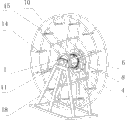
Fig. 1 is a contactless trailing cable drum device overall structure schematic diagram.
Fig. 2 is the schematic diagram of disassembling of contactless trailing cable drum device.
Fig. 3 is an internal layer reel assemblies structural representation in the contactless trailing cable drum device.
Fig. 4 is the structural representation of right spindle nose.
Fig. 5 is that the contactless trailing cable drum device cable twines view.
Number among the figure: 1. cable inlet, 2. cable intermediate plate, 3. wire clamp sheet, 4. hollow shaft, 5. line ball clip, 6. volute spring, 7. coil spring seat, 8. bearing, 9. bearing cap, 10. big wheel body, 11. left spindle noses, 12. right spindle noses, 13. fluting, 14. take turns support, 15. stulls, 16. wire clamps, 17. the line ball folder, 18. bracing frames, 19. flat cables, 20. the wind spring fixed axis, 21. wind spring ends, 22. baffle plates.
Embodiment
Be described further below in conjunction with the structure of accompanying drawing contactless trailing cable drum device.
Illustrated in figures 1 and 2 is the overall structure schematic diagram of contactless trailing cable drum device embodiment, this device is made up of bracing frame 18, big wheel body 10, internal layer reel assemblies and volute spring 6, and the internal layer reel assemblies comprises hollow shaft 4, bearing 8, bearing cap 9 and left spindle nose 11 and the right spindle nose 12 that is made of several cylinder stulls; Hollow shaft 4 is used to twine cable, and bearing 8, bearing cap 9 are installed in the two ends of internal layer reel assemblies hollow shaft 4 respectively, and left spindle nose 11 and right spindle nose 12 are spirally connected with the bearing cap at hollow shaft two ends respectively.On the termination of internal layer reel assemblies left side spindle nose 11, be provided with cable inlet 1, on the right spindle nose 12 coil spring seat 7 is installed, this coil spring seat is loaded on the right outside of big wheel body, and it is affixed with internal layer reel assemblies right-hand member bearing cap, volute spring 6 is housed in the coil spring seat, volute spring 6 is sleeved on the termination of right spindle nose 12, and an end of this volute spring is fixed in the fluting 13 of right spindle nose termination, and wind spring end 21 is fixed in (with reference to figure 3, Fig. 4) on the wind spring fixed axis 20.
In the present embodiment, described big wheel body 10 is based on hexagonal, and hexagonal each drift angle extended line stretches out and the external circle welding of bull wheel, and hexagonal drift angle extended line extends internally and big wheel body inner ring welding; Be welded with several on the external circle of bull wheel and take turns support 14, hexagonal extended line is provided with several stulls 15, in a stull wire clamp 16 and line ball folder 17 is housed therein.The inner ring diameter of big wheel body 10 equates that with the cylindrical of internal layer reel assemblies bearings at both ends 8 big wheel body is embedded on the bearing at internal layer reel assemblies two ends, and is spirally connected by bearing cap 9; The spindle nose at internal layer reel assemblies two ends sets up and is fixed in the U type mouth of bracing frame 18.This structure becomes one big wheel body and internal layer reel assemblies, and the spindle nose at internal layer reel assemblies two ends sets up and is fixed in the U type mouth of bracing frame 18, makes that the internal layer reel assemblies is motionless, and big wheel body 10 is by the bearing rotation at internal layer reel assemblies two ends.
Referring to Fig. 5.When using this device, flat cable 19 enters on the hollow shaft of being made up of several cylinder stulls 4 from the cable inlet 1 of internal layer reel assemblies one end, and wire clamp sheet 3, line ball clip 5 compress (as shown in Figure 3) with the inner of flat cable 19; Flat cable twines a few on hollow shaft, twine to the stull 15 and the wheel support 14 of big wheel body 10 again, wire clamp 16 in the stull 15 and line ball folder 17 are stretching fixing with flat cable 19, and flat cable is reeled on big wheel body and drawn over to one's side, and does corresponding coiling on the hollow shaft 4 of internal layer reel assemblies.
Drive flat cable 19 and discharge when suspension equipment (suspension rod) descends, big wheel body 10 rotates, and this moment, volute spring 6 was in rolling-in energy storage state.When suspension equipment (suspension rod) rose, volute spring 6 entered that releases can state, drives big wheel body 10 backward rotation, thereby realized that flat cable reels when drawing over to one's side on big wheel body, also did corresponding coiling on the internal layer reel assemblies.When suspension equipment lifting during to the height that needs, because the effect of volute spring, make the stressed poised state that is in of reel, reel will stop with suspension equipment.
The contactless cable drum device of the utility model is without slip ring and brush, by the rotation of big wheel body, drive twisted and released of the cable, and drive cable simultaneously and on the internal layer reel, makes corresponding coiling, thereby avoided reversing of cable stiff end, realized contactless current delivery; By the effect of volute spring, make the stressed poised state that is in of reel simultaneously, realized the synchronous operation of cable with lifting means.
Claims (6)
1, a kind of contactless trailing cable drum device, this device comprise bracing frame (18), big wheel body (10), internal layer reel assemblies and volute spring (6), it is characterized in that:
Described internal layer reel assemblies comprises one can twine the hollow shaft (4) of cable, be installed in bearing (8), bearing cap (9), left spindle nose (11) and the right spindle nose (12) at hollow shaft two ends respectively; The termination of wherein left spindle nose (11) is provided with cable inlet (1), and flat cable (19) enters cable inlet, is set with volute spring (6) on the termination of right spindle nose (12);
Described big wheel body (10) is embedded on the bearing at internal layer reel assemblies two ends, and is spirally connected by bearing cap; The spindle nose at internal layer reel assemblies two ends sets up and is fixed in the U type mouth of bracing frame (18), and big wheel body rotates by bearing.
2, contactless trailing cable drum device as claimed in claim 1, it is characterized in that: described big wheel body (10) is based on hexagonal, hexagonal each drift angle extended line stretches out and the external circle welding of bull wheel, and hexagonal drift angle extended line extends internally and big wheel body inner ring welding; Be welded with several on the external circle of bull wheel and take turns support (14), hexagonal extended line is provided with several stulls (15), in a stull wire clamp (16) and line ball folder (17) is housed therein.
3, contactless trailing cable drum device as claimed in claim 1 is characterized in that: an end of described volute spring (6) is fixed in the fluting (13) of the right spindle nose of internal layer reel assemblies termination, and wind spring end (21) is fixed on the wind spring fixed axis (20).
4, contactless trailing cable drum device as claimed in claim 1 is characterized in that: the hollow shaft of described internal layer reel assemblies (4) is made of several cylinder stulls.
5, contactless trailing cable drum device as claimed in claim 1, it is characterized in that: described cable inlet (1) is to establish an opening on internal layer reel assemblies left side, one baffle plate (22) is stuck in the opening, the affixed cable intermediate plate (2) in baffle plate top, this baffle plate (22) and cable intermediate plate (2) constitute cable inlet on the left side of internal layer reel assemblies.
6, contactless trailing cable drum device as claimed in claim 2, it is characterized in that: described flat cable (19) is gone up winding at the hollow shaft (4) of internal layer reel assemblies, and a few twine to the stull (15) and the wheel support (14) of big wheel body (10) again, wire clamp (16) in the stull (15) and line ball folder (17) are stretching fixing with flat cable (19), when flat cable (19) is drawn over to one's side at the last coiling of big wheel body (10), on the hollow shaft (4) of internal layer reel assemblies, also do corresponding coiling.
Priority Applications (1)
| Application Number | Priority Date | Filing Date | Title |
|---|---|---|---|
| CN 200820123076 CN201286005Y (en) | 2008-10-22 | 2008-10-22 | Contactless trailing cable drum device |
Applications Claiming Priority (1)
| Application Number | Priority Date | Filing Date | Title |
|---|---|---|---|
| CN 200820123076 CN201286005Y (en) | 2008-10-22 | 2008-10-22 | Contactless trailing cable drum device |
Publications (1)
| Publication Number | Publication Date |
|---|---|
| CN201286005Y true CN201286005Y (en) | 2009-08-05 |
Family
ID=40950973
Family Applications (1)
| Application Number | Title | Priority Date | Filing Date |
|---|---|---|---|
| CN 200820123076 Expired - Fee Related CN201286005Y (en) | 2008-10-22 | 2008-10-22 | Contactless trailing cable drum device |
Country Status (1)
| Country | Link |
|---|---|
| CN (1) | CN201286005Y (en) |
-
2008
- 2008-10-22 CN CN 200820123076 patent/CN201286005Y/en not_active Expired - Fee Related
Similar Documents
| Publication | Publication Date | Title |
|---|---|---|
| CN107954274A (en) | A kind of portable antiwind cable reel | |
| CN100583583C (en) | Contactless trailing cable drum device | |
| CN202936027U (en) | Winding machine | |
| CN206014073U (en) | Admission machine | |
| CN201010469Y (en) | Multi-layer coiling and hoisting mechanism | |
| CN105413100A (en) | Fitness equipment and pull rope device | |
| CN207876919U (en) | A kind of flexible membrane rolling-up mechanism | |
| CN201286005Y (en) | Contactless trailing cable drum device | |
| CN209651738U (en) | A kind of crane anti-swing system | |
| CN216235408U (en) | Shore power cable winch capable of automatically arranging cables | |
| CN207566585U (en) | A kind of covering machine of weaving | |
| CN201771399U (en) | Improved curtain folding and unfolding mechanism | |
| CN208716481U (en) | Aluminium foil winding device | |
| CN212197972U (en) | Wire coiling device for computer communication network | |
| CN211769536U (en) | Novel cable winding and unwinding turntable | |
| CN208037726U (en) | A kind of copper free wire spooling equipment | |
| CN208948589U (en) | A kind of twisted and released of the cable frame facilitating control line | |
| CN208249559U (en) | A kind of movable roll of copper wire processing | |
| CN218619537U (en) | Cable pay-off for power construction | |
| CN109119208A (en) | A kind of small tension receiving coil cage winch bobbin loader | |
| CN110004678A (en) | Tray thread depressing mechanism and power machine core and clothes airing machine | |
| CN219990748U (en) | Automatic electric power construction pay-off of tension adjustment | |
| CN201183728Y (en) | Drag rope deploying and retracting apparatus | |
| CN209940101U (en) | Pay-off is used in electric power construction | |
| CN216338585U (en) | Winding power driving mechanism for electric clothes hanger |
Legal Events
| Date | Code | Title | Description |
|---|---|---|---|
| C14 | Grant of patent or utility model | ||
| GR01 | Patent grant | ||
| C17 | Cessation of patent right | ||
| CF01 | Termination of patent right due to non-payment of annual fee |
Granted publication date: 20090805 Termination date: 20101022 |