CN201258729Y - Prepositive hydraulic balancing beam-pumping unit - Google Patents
Prepositive hydraulic balancing beam-pumping unit Download PDFInfo
- Publication number
- CN201258729Y CN201258729Y CNU2008201903725U CN200820190372U CN201258729Y CN 201258729 Y CN201258729 Y CN 201258729Y CN U2008201903725 U CNU2008201903725 U CN U2008201903725U CN 200820190372 U CN200820190372 U CN 200820190372U CN 201258729 Y CN201258729 Y CN 201258729Y
- Authority
- CN
- China
- Prior art keywords
- pumping unit
- oil
- walking beam
- cavity
- connecting rod
- Prior art date
- Legal status (The legal status is an assumption and is not a legal conclusion. Google has not performed a legal analysis and makes no representation as to the accuracy of the status listed.)
- Expired - Fee Related
Links
Images

Landscapes
- Reciprocating Pumps (AREA)
Abstract
The utility model relates to a front hydraulic balanced beam pumping unit, which comprises a balancing device, a horse head, a beam, a crank connecting rod driving mechanism, a motor, a pumping unit base, a bracket and a pumping rod. The utility model is characterized in that the upper end of the balancing device is hinged with the beam; the lower end thereof is hinged with the pumping unit base; the upper hinging point is arranged on the beam between the bracket and the horse head; the hinging point of the connecting rod is arranged on the beam between the bracket and the balancing device; the balancing device consists of a piston cylinder, a gas tank, an oil pipe, high-pressure nitrogen and hydraulic oil; the upper cavity of the gas tank is filled with the high-pressure nitrogen; the lower cavity thereof is filled with the hydraulic oil; and the lower cavity of the balancing cylinder piston is communicated with the hydraulic oil in the lower cavity of the gas tank through the built-in oil pipe. Therefore, the utility model not only can provide relatively steady balance force for the beam pumping unit, but also can conveniently adjust the balance force to achieve the power-saving effect according to the operating condition of the pumping unit.
Description
Technical field
The utility model relates to a kind of oil field equipment, especially for the energy-saving hydraulic beam-balanced pumping unit of oil field oil recovery.
Background technology
At present, knowing the balance of beam-pumping unit from known data, is to add balance weight iron on the beam-pumping unit crank, when oil pumper is worked, and load when balanced oil extractor partly rises and the part gravity of sucker rod when descending.But this structure constitutional balance effect is bad, and very power consumption when adjusting equilibrant force, needs mobile counterweight iron, and very difficulty so more aggravated energy consumption, for falling energy consumption, is used the energy-conservation two horse head beam-pumping units of more common beam-pumping unit, but relatively power consumption still.
Summary of the invention
The purpose of this utility model provides a new forward type hydro-cushion beam-pumping unit, and it can not only be for beam-pumping unit provides more stable equilibrant force, and can be according to the operating mode of oil pumper, and adjustment power easily reaches the effect of economize on electricity.
This practical technical scheme is: a kind of forward type hydro-cushion beam-pumping unit, comprise bascule, horse head, walking beam, crank linkage driving system, motor, oil pumping unit base, support, sucker rod, it is characterized in that: the upper end and the walking beam of bascule are hinged, lower end and oil pumping unit base are hinged, last hinge is positioned on the walking beam between support and horse head, and the last hinge of connecting rod is positioned on the walking beam between support and bascule; Bascule is made of piston oil-cylinder, gas-accumulating tank, oil pipe, high pressure nitrogen and hydraulic oil, and the gas-accumulating tank epicoele is equipped with high pressure nitrogen, and cavity of resorption is equipped with hydraulic oil, and balancing cylinder piston cavity of resorption is by the hydraulic oil of built-in oil pipe UNICOM gas-accumulating tank cavity of resorption.
Aforesaid forward type hydro-cushion beam-pumping unit, it is characterized in that: described crank linkage driving system is made of connecting rod, crank, reductor, big belt pulley, belt and small belt pulley, crank on the reductor output connects walking beam by connecting rod, motor connects the big belt pulley on the reductor input by small belt pulley, belt.
Forward type hydro-cushion oil pumper of the present utility model is rational in infrastructure, adjust the size of nitrogen pressure in the accumulator, also just changed the size of equilibrant force, can be according to the variation of oil well condition, adjust the only equilibrant force of oil pumper easily, the power savings that can obtain.The reductor of oil pumper, brace and connecting rod framework and bascule all are installed in the support front, and under appearance and size, the stroke of oil pumper is longer, good energy-conserving effect.
Description of drawings
Fig. 1 is the structure chart of the utility model embodiment.
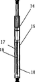
Fig. 2 is the structure chart of bascule among Fig. 1.
The specific embodiment
Below in conjunction with drawings and Examples the utility model is further specified.
The explanation of mark among Fig. 1: 1-bascule; 2-horse head; 3-walking beam; 4-connecting rod; 5-crank; 6-reductor; 7-big belt pulley; 8-belt; 9-small belt pulley; 10-motor; 11-oil pumping unit base; 12-support; 13-sucker rod.
The explanation of mark among Fig. 2: 14-piston oil-cylinder; 15-gas-accumulating tank; 16-oil pipe; 17-high pressure nitrogen; 18-hydraulic oil.
Referring to Fig. 1, the forward type hydro-cushion beam-pumping unit of the utility model embodiment, comprise bascule 1, horse head 2, walking beam 3, crank linkage driving system, motor 10, oil pumping unit base 11, support 12, sucker rod 13, it is characterized in that: the upper end of bascule 1 and walking beam 3 are hinged, lower end and oil pumping unit base 11 are hinged, last hinge is positioned on the walking beam 3 of 2 of support 12 and horse heads, the last hinge of connecting rod 4 is positioned on the walking beam 3 of 1 of support 12 and bascule, bascule 1 is by piston oil-cylinder 14, gas-accumulating tank 15, oil pipe 16, high pressure nitrogen 17 and hydraulic oil 18 constitute, gas-accumulating tank 15 epicoeles are equipped with high pressure nitrogen 17, cavity of resorption is equipped with hydraulic oil 18, and balancing cylinder 14 piston cavity of resorptions are by the hydraulic oil 18 of built-in oil pipe 16 UNICOM's gas-accumulating tanks 15 cavity of resorptions.
The described crank linkage driving system of the utility model embodiment is made of connecting rod 4, crank 5, reductor 6, big belt pulley 7, belt 8 and small belt pulley 9, crank 5 on reductor 6 outputs connects walking beam 3 by connecting rod 4, motor 10 connects the big belt pulley 7 on reductor 6 inputs by small belt pulley 9, belt 8.
From Fig. 1 as seen, the oil cylinder piston bar upper end on hydraulic balance device 1 top is hinged on walking beam 3 leading portions, lower hinge is on oil pumping unit base 11, the rear end of walking beam 3 is hinged on the support 12, crank linkage driving system connects walking beam 3 by the crank on reductor 6 outputs 5 by connecting rod 4, motor 10 is by small belt pulley 9, belt 8, and the big belt pulley 7 that connects on reductor 6 inputs is formed.Hydraulic balance device 1 is to be connected to form by balancing cylinder 14, gas-accumulating tank 15, inner oil pipe 16, and gas-accumulating tank 15 epicoeles are equipped with high pressure nitrogen 17, and cavity of resorption is equipped with hydraulic oil 18.Balancing cylinder 14 piston cavity of resorptions are by the hydraulic oil 18 of built-in oil pipe 16 UNICOM's gas-accumulating tanks 15 cavity of resorptions.When oil pumper is up, motor 10 is by small belt pulley 9, belt 8, connect the big belt pulley 7 on reductor 6 inputs, driving walking beam 3 by crank 5 connecting rods 4 mechanisms moves up and down, when horse head 2 was up, the hydraulic oil 18 of hydraulic balance device 1, gas-accumulating tank 15 cavity of resorptions entered balancing cylinder 14 cavity of resorptions by oil pipe 16, acts on the piston rod, produce thrust upwards, balance the whole gravity and the part crude oil liquid lifting force of sucker rod 13 in the oil well.When horse head 2 was descending, under the dynamic action of the gravity of sucker rod 13 and oil pumper, the compressing piston rod was descending, hydraulic oil 18 in balancing cylinder 14 cavity of resorptions enters gas-accumulating tank 15 cavity of resorptions by oil pipe 16, process on repeating again when oil pumper rises reaches and reduces oil pumper load, energy-conservation order.According to the variation of oil well condition and load, adjust the size of gas-accumulating tank 15 inner high voltage nitrogen 17 pressure, also just changed the size of equilibrant force, can obtain better power savings.
Claims (2)
1, a kind of forward type hydro-cushion beam-pumping unit, comprise bascule, horse head, walking beam, crank linkage driving system, motor, oil pumping unit base, support, sucker rod, it is characterized in that: the upper end and the walking beam of bascule are hinged, lower end and oil pumping unit base are hinged, last hinge is positioned on the walking beam between support and horse head, and the last hinge of connecting rod is positioned on the walking beam between support and bascule; Bascule is made of piston oil-cylinder, gas-accumulating tank, oil pipe, high pressure nitrogen and hydraulic oil, and the gas-accumulating tank epicoele is equipped with high pressure nitrogen, and cavity of resorption is equipped with hydraulic oil, and balancing cylinder piston cavity of resorption is by the hydraulic oil of built-in oil pipe UNICOM gas-accumulating tank cavity of resorption.
2, forward type hydro-cushion beam-pumping unit as claimed in claim 1, it is characterized in that: described crank linkage driving system is made of connecting rod, crank, reductor, big belt pulley, belt and small belt pulley, crank on the reductor output connects walking beam by connecting rod, motor connects the big belt pulley on the reductor input by small belt pulley, belt.
Priority Applications (1)
| Application Number | Priority Date | Filing Date | Title |
|---|---|---|---|
| CNU2008201903725U CN201258729Y (en) | 2008-08-19 | 2008-08-19 | Prepositive hydraulic balancing beam-pumping unit |
Applications Claiming Priority (1)
| Application Number | Priority Date | Filing Date | Title |
|---|---|---|---|
| CNU2008201903725U CN201258729Y (en) | 2008-08-19 | 2008-08-19 | Prepositive hydraulic balancing beam-pumping unit |
Publications (1)
| Publication Number | Publication Date |
|---|---|
| CN201258729Y true CN201258729Y (en) | 2009-06-17 |
Family
ID=40772963
Family Applications (1)
| Application Number | Title | Priority Date | Filing Date |
|---|---|---|---|
| CNU2008201903725U Expired - Fee Related CN201258729Y (en) | 2008-08-19 | 2008-08-19 | Prepositive hydraulic balancing beam-pumping unit |
Country Status (1)
| Country | Link |
|---|---|
| CN (1) | CN201258729Y (en) |
Cited By (3)
| Publication number | Priority date | Publication date | Assignee | Title |
|---|---|---|---|---|
| CN102828727A (en) * | 2012-07-24 | 2012-12-19 | 东营市华科石油科技开发有限责任公司 | Horsehead straightening device for oil pumping unit |
| CN109252831A (en) * | 2018-11-13 | 2019-01-22 | 唐山渤海冶金智能装备有限公司 | A kind of balancing device and its application method for hydraulic pumping unit |
| CN112502672A (en) * | 2021-02-03 | 2021-03-16 | 山东龙尚石油科技有限责任公司 | Front-mounted beam complementary balance pumping unit |
-
2008
- 2008-08-19 CN CNU2008201903725U patent/CN201258729Y/en not_active Expired - Fee Related
Cited By (4)
| Publication number | Priority date | Publication date | Assignee | Title |
|---|---|---|---|---|
| CN102828727A (en) * | 2012-07-24 | 2012-12-19 | 东营市华科石油科技开发有限责任公司 | Horsehead straightening device for oil pumping unit |
| CN109252831A (en) * | 2018-11-13 | 2019-01-22 | 唐山渤海冶金智能装备有限公司 | A kind of balancing device and its application method for hydraulic pumping unit |
| CN109252831B (en) * | 2018-11-13 | 2024-01-30 | 唐山渤海冶金智能装备有限公司 | Balancing device for hydraulic pumping unit and application method thereof |
| CN112502672A (en) * | 2021-02-03 | 2021-03-16 | 山东龙尚石油科技有限责任公司 | Front-mounted beam complementary balance pumping unit |
Similar Documents
| Publication | Publication Date | Title |
|---|---|---|
| CN201176865Y (en) | Hydraulic balancing beam-pumping unit | |
| CN203847073U (en) | Gas balance type hydraulic oil pumping machine | |
| CN201258729Y (en) | Prepositive hydraulic balancing beam-pumping unit | |
| CN201162660Y (en) | Hydraulic secondary balancing device of beam pumping unit | |
| CN201401157Y (en) | Hydrodynamic balance column beam-pumping unit | |
| CN201059162Y (en) | Hydro-cylinder lifting type folding derrick | |
| CN202707004U (en) | Double-horsehead energy-saving oil pumping unit | |
| CN203559881U (en) | Gas-balancing hydraulic oil pumping unit | |
| CN201344024Y (en) | Double-cylinder symmetrical-type equilibrium hydraulic pumping unit | |
| CN103670343B (en) | Hydraulic oil pumping drive unit | |
| CN203778852U (en) | Pipe cutting machine | |
| CN201007198Y (en) | Directly balancing flexible drive oil pumping machine | |
| CN201620843U (en) | Hydraulic pumping unit for petroleum | |
| CN202467777U (en) | Hydraulic energy-saving beam-pumping unit | |
| CN101539004A (en) | Epicycloidal beam pumping unit | |
| CN201908814U (en) | Two-stage pump cylinder and two-stage plunger piston combined pump cylinder pipe type pump | |
| CN202300328U (en) | Diameter-adjustable and moment-variable oil pumping unit | |
| CN205677585U (en) | A kind of hybrid efficient long stroke hydraulic pumping unit | |
| CN103075133A (en) | Flow compensation type hydraulic pumping unit | |
| CN208311357U (en) | One kind having the dust-proof motor-driven jack bracket of buffer structure both legs support type | |
| CN205936540U (en) | Energy storage balanced type hydraulic pumping unit | |
| CN202031549U (en) | Pneumatic-balance hydraulic pumping unit for offshore platform | |
| CN202718663U (en) | Casing gas recovery device for mechanized oil well | |
| CN111894535B (en) | Two-stage telescopic ocean platform hydraulic pumping unit, control method and application | |
| CN103288005A (en) | Manual rapid portable extra-high-pressure hydraulic jack |
Legal Events
| Date | Code | Title | Description |
|---|---|---|---|
| C14 | Grant of patent or utility model | ||
| GR01 | Patent grant | ||
| C17 | Cessation of patent right | ||
| CF01 | Termination of patent right due to non-payment of annual fee |
Granted publication date: 20090617 Termination date: 20120819 |