CN201159030Y - Two-sided opening door structure - Google Patents
Two-sided opening door structure Download PDFInfo
- Publication number
- CN201159030Y CN201159030Y CNU2008200786688U CN200820078668U CN201159030Y CN 201159030 Y CN201159030 Y CN 201159030Y CN U2008200786688 U CNU2008200786688 U CN U2008200786688U CN 200820078668 U CN200820078668 U CN 200820078668U CN 201159030 Y CN201159030 Y CN 201159030Y
- Authority
- CN
- China
- Prior art keywords
- door body
- latch
- door
- controller
- pin thread
- Prior art date
- Legal status (The legal status is an assumption and is not a legal conclusion. Google has not performed a legal analysis and makes no representation as to the accuracy of the status listed.)
- Expired - Fee Related
Links
Images


Landscapes
- Casings For Electric Apparatus (AREA)
Abstract
The utility model relates to a door body structure capable of being opened and closed from two sides, which comprises a door body and a frame body, wherein male buttons and female buttons whose sizes and positions are matched are arranged on the door body and the frame body, the male buttons of the door body are arranged on the left and the right inner walls, vertical plug holes are arranged on the mal buttons, a door handle is arranged on the external surface of the door body, a key is arranged on the inner side of the door handle and is connected with a trigger which is arranged on the inner wall of the door body through a line, the female buttons are arranged on the front surface of the frame body, plug grooves are arranged in the female buttons, and plugs are arranged in the plug grooves, control springs which are fixedly connected with the plugs are arranged on the bottoms of the plug grooves, arcuate male button continuous slots are arranged on the sides of the female buttons, a plug-stretching controller is arranged on the frame body, the position of the controller is matched with a trigger which is arranged on the inner wall of the door body, and the controller is connected with the control springs which are arranged on the bottoms of the plug grooves through a line. The door body structure of the utility model is capable of being opened and closed from two sides, is more suitable for being used in limited space conditions, and has convenient operation.
Description
Technical field
The utility model relates to a kind of door, especially relates to a kind of two door body structure that draws of opening.
Background technology
At present, the door body is monolateral switch normally, that is to say a body around a fixedly single shaft rotation, and this angle that makes door body rotate can only be confined to a certain fixing scope, cause a body in use often to bring inconvenience, especially under the limited condition of usage space.
The utility model content
The technical problems to be solved in the utility model provides a kind of two door body structure that draws of opening, and the bilateral switch of this door body structure energy can more be applicable to limited steric requirements, and easy to operate.
For solving the problems of the technologies described above, the utility model adopts following technical scheme: open the door body structure that draws for a kind of pair, it comprises a body and framework; Described door body and framework are provided with pin thread and box big or small and that mate mutually the position;
The pin thread of described door body is arranged on the left and right inwall, is provided with at least two on the same vertical axis in door body both sides, and this pin thread is provided with vertical pin hole; Two door handles about described door external surface is provided with, the inboard of this door handle is provided with button, and this button is connected with a trigger on being arranged on a body inwall by call wire;
Described framework front is provided with box, is provided with the latch groove in this box, is provided with latch in this latch groove, and the pin hole on the position of this latch and size and the pin thread is complementary, and described latch trench bottom is provided with the control spring of fixedlying connected with latch; For making the pin thread box of coming in and going out smoothly, described box side is provided with arc pin thread turnover groove, otherwise can be subjected to certain obstruction because of the anglec of rotation of pin thread during pin thread turnover box; Described framework is provided with the latch expansion controller, and the toggle position on the position of this controller and the door body inwall is complementary, and this controller is connected by the control spring of call wire with the latch trench bottom.
The bilateral switch of the utility model door body structure energy can more be applicable to limited steric requirements, and easy to operate.
Description of drawings
Below in conjunction with accompanying drawing the specific embodiment of the present utility model is described in further detail
Fig. 1 is door body of the present utility model and framework fit structure schematic diagram;
Fig. 2 is a framework Facad structure schematic diagram of the present utility model;
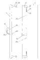
Fig. 3 is a door body inner surface structure schematic diagram of the present utility model;
Fig. 4 is the A portion partial enlarged drawing among Fig. 2.
The specific embodiment
Shown in Fig. 1,2,3 and 4, the utility model comprises a body 1 and framework 2; Described door body 1 and framework 2 are provided with pin thread 11 and box 21 big or small and that mate mutually the position;
The pin thread 11 of described door body 1 is arranged on the left and right inwall, is provided with two on the same vertical axis in door body 1 both sides, and this pin thread 11 is provided with vertical pin hole 111; Two door handles 12 about described door body 1 external surface is provided with, the inboard of this door handle 12 is provided with button 121, and this button 121 is connected with trigger 123 on being arranged on a body 1 inwall by call wire 122;
Described framework 2 fronts are provided with box 21, be provided with latch groove 22 in this box 21, be provided with latch 23 in this latch groove 22, the pin hole 111 on the position of this latch 23 and size and the pin thread 11 is complementary, and described latch groove 22 bottoms are provided with the control spring 24 of fixedlying connected with latch 23; For making pin thread 11 box 21 of coming in and going out smoothly, described box 21 sides are provided with arc pin thread turnover groove 211; Described framework 1 is provided with latch expansion controller 25, and trigger 123 positions on the position of this controller 25 and door body 1 inwall are complementary, and this controller 25 is connected by the control spring 24 of call wire 251 with latch groove 22 bottoms.
Operating principle of the present utility model is as follows:
Referring to shown in Figure 1, the pin thread 11 of door body 1 is fixed in the box 21 of framework 2 in the time of in off position, and latch 23 passes the pin hole 111 on the pin thread 11, and whole door body 1 can be fixed on the framework 2 by latch 23, and can be one-sided around latch 23 rotations;
Press the button 121 on the door handle 12, be transferred to trigger 123 by call wire 122, trigger 123 starts latch expansion controller 25, controller 25 drives to control spring 24 in the latch groove 22 by call wire 251, make control spring 24 shrink, thereby drive in the latch 23 retraction latch grooves 22, this side of door body 1 has got final product Unscrew;
Close a body fully after, press the button 121 on the door handle 12, be transferred to trigger 123 by call wire 122, trigger 123 starts latch expansion controller 25, controller 25 drives to control spring 24 in the latch groove 22 by call wire 251, makes control spring 24 eject, and ejects thereby drive latch 23, make latch 23 pass pin hole 111 on the pin thread 11, door body 1 and framework 2 are fixing.
The utility model is controlled left and right sides side door handle button respectively, can make a side rotate, open and close around opposite side, thereby has realized the function of bilateral switch.
Obviously, the foregoing description of the present utility model only is for the utility model example clearly is described, and is not to be qualification to embodiment of the present utility model.For those of ordinary skill in the field, can also make other changes in different forms on the basis of the above description.Here can't give exhaustive to all embodiments.Everyly belong to the row that conspicuous variation that the technical solution of the utility model extends out or change still are in protection domain of the present utility model.
Claims (1)
1, open the door body structure that draws for a kind of pair, it comprises a body and framework; Described door body and framework are provided with pin thread and box big or small and that mate mutually the position, it is characterized in that:
The pin thread of described door body is arranged on the left and right inwall, is provided with at least two on the same vertical axis in door body both sides, and this pin thread is provided with vertical pin hole; Two door handles about described door external surface is provided with, the inboard of this door handle is provided with button, and this button is connected with a trigger on being arranged on a body inwall by call wire;
Described framework front is provided with box, is provided with the latch groove in this box, is provided with latch in this latch groove, and the pin hole on the position of this latch and size and the pin thread is complementary, and described latch trench bottom is provided with the control spring of fixedlying connected with latch; Described box side is provided with arc pin thread turnover groove; Described framework is provided with the latch expansion controller, and the toggle position on the position of this controller and the door body inwall is complementary, and this controller is connected by the control spring of call wire with the latch trench bottom.
Priority Applications (1)
| Application Number | Priority Date | Filing Date | Title |
|---|---|---|---|
| CNU2008200786688U CN201159030Y (en) | 2008-01-22 | 2008-01-22 | Two-sided opening door structure |
Applications Claiming Priority (1)
| Application Number | Priority Date | Filing Date | Title |
|---|---|---|---|
| CNU2008200786688U CN201159030Y (en) | 2008-01-22 | 2008-01-22 | Two-sided opening door structure |
Publications (1)
| Publication Number | Publication Date |
|---|---|
| CN201159030Y true CN201159030Y (en) | 2008-12-03 |
Family
ID=40109616
Family Applications (1)
| Application Number | Title | Priority Date | Filing Date |
|---|---|---|---|
| CNU2008200786688U Expired - Fee Related CN201159030Y (en) | 2008-01-22 | 2008-01-22 | Two-sided opening door structure |
Country Status (1)
| Country | Link |
|---|---|
| CN (1) | CN201159030Y (en) |
Cited By (2)
| Publication number | Priority date | Publication date | Assignee | Title |
|---|---|---|---|---|
| CN103015818A (en) * | 2012-12-05 | 2013-04-03 | 宋爱平 | Doorknob with plug pin |
| CN103556907A (en) * | 2013-11-20 | 2014-02-05 | 王博 | Single-sash double-opening cabinet door |
-
2008
- 2008-01-22 CN CNU2008200786688U patent/CN201159030Y/en not_active Expired - Fee Related
Cited By (2)
| Publication number | Priority date | Publication date | Assignee | Title |
|---|---|---|---|---|
| CN103015818A (en) * | 2012-12-05 | 2013-04-03 | 宋爱平 | Doorknob with plug pin |
| CN103556907A (en) * | 2013-11-20 | 2014-02-05 | 王博 | Single-sash double-opening cabinet door |
Similar Documents
| Publication | Publication Date | Title |
|---|---|---|
| CN106902598B (en) | A kind of Environmental-protection dust removal device | |
| USD581880S1 (en) | Wireless extension unit for an irrigation controller | |
| CN106711829B (en) | A kind of power distribution cabinet from locking power supply | |
| CN201173038Y (en) | Dual spindle spring double doors | |
| CN203871593U (en) | Mechanical linkage socket | |
| CN201159030Y (en) | Two-sided opening door structure | |
| CN103017440B (en) | Refrigerator | |
| USD618176S1 (en) | Electrical connector | |
| CN201763077U (en) | Humanized counter locking intelligent lock | |
| CN102535118A (en) | Novel power door lock for washing machine | |
| CN202273502U (en) | Structure of lock of switch cabinet door | |
| CN201159031Y (en) | Two-sided opening door structure | |
| EP2611270A3 (en) | Socket for electric parts | |
| CN203662590U (en) | Electric oven with side-by-side doors | |
| CN202671904U (en) | Washing machine door cover and washing machine | |
| CN201714238U (en) | Easy-to-open/close sliding window | |
| CN201546076U (en) | Washing machine door lock | |
| CN209877602U (en) | Packaging bottle drying device | |
| CN203559654U (en) | Automatic unlocking device of electric anti-theft lock | |
| CN201360014Y (en) | Opening-closing device of door lock battery box cover | |
| CN203039277U (en) | Valve self-locking mechanism of centrally-mounted switch cabinet | |
| CN201850843U (en) | Power-assisted door handle assembly and electrical equipment | |
| CN206992520U (en) | A kind of protector that powered enabling is prevented for power distribution cabinet | |
| CN201222626Y (en) | Electric appliance switch cabinet handle with self-locking mechanism | |
| USD640714S1 (en) | Grinder |
Legal Events
| Date | Code | Title | Description |
|---|---|---|---|
| C14 | Grant of patent or utility model | ||
| GR01 | Patent grant | ||
| C17 | Cessation of patent right | ||
| CF01 | Termination of patent right due to non-payment of annual fee |
Granted publication date: 20081203 Termination date: 20120122 |