CN201155155Y - Shearing -type lead damper - Google Patents
Shearing -type lead damper Download PDFInfo
- Publication number
- CN201155155Y CN201155155Y CNU2008200788787U CN200820078878U CN201155155Y CN 201155155 Y CN201155155 Y CN 201155155Y CN U2008200788787 U CNU2008200788787 U CN U2008200788787U CN 200820078878 U CN200820078878 U CN 200820078878U CN 201155155 Y CN201155155 Y CN 201155155Y
- Authority
- CN
- China
- Prior art keywords
- shorn
- utility
- sliding plate
- shearing
- lead
- Prior art date
- Legal status (The legal status is an assumption and is not a legal conclusion. Google has not performed a legal analysis and makes no representation as to the accuracy of the status listed.)
- Expired - Fee Related
Links
- 238000010008 shearing Methods 0.000 title claims description 28
- 208000002925 dental caries Diseases 0.000 claims description 6
- 238000004519 manufacturing process Methods 0.000 abstract description 2
- 238000010521 absorption reaction Methods 0.000 abstract 1
- 230000035939 shock Effects 0.000 abstract 1
- 230000014759 maintenance of location Effects 0.000 description 2
- 238000013016 damping Methods 0.000 description 1
- 230000007547 defect Effects 0.000 description 1
- 238000010586 diagram Methods 0.000 description 1
- 238000005516 engineering process Methods 0.000 description 1
- 238000000034 method Methods 0.000 description 1
Images


Abstract
The utility model relates to a shear pattern lead damper which can be applicable to shock absorption control of the building structure. The utility model comprises an upper and a lower cover board 1 and a sliding plate 2. The two cover boards 1 are respectively locked on the upper and lower surfaces of the sliding plate 2. Four grooves are opened on all the contact surfaces of the two cover boards 1 and the sliding plate 2. The positions of four grooves are opposite to each other and the sizes are identical to form two upper and lower cavities. Shorn quadrats 3 are directly embedded within two cavities. A plurality of screws 5 passes through two cover boards 1 and are locked with lock nuts 4. Two cover boards 1 and the sliding plate 2 and the shorn quadrats 3 clipped between two cover boards 1 are fixed. The utility model simplifies the shorn lead block of the conventional shorn lead damper into the shorn quadrat. The shorn quadrat is directly embedded into the grooves of the cover board and the sliding plate, which simplifies connection of the quadrat and the cover board. The utility model is simple in structure and convenient in processing. The manufacture cost is reduced and the hysteretic performance remains constant with high practical application value.
Description
Technical field
The utility model relates to a kind of shearing type lead damper, can be applicable to building structure damping control.
Background technology
Lead damper is a kind of control device that a class is utilized plumbous plastic strain dissipation vibrational energy.Conventional shearing lead damper as shown in Figure 1.Such damper comprises two cover plates 1, sliding panels 2 and shearing lead blocks 6 up and down.The major defect that routine shown in Figure 1 is sheared lead damper is that shearing lead block 6 is comparatively difficult with being connected of two cover plates 1, adds and expends too much man-hour and plumbous material man-hour.
The utility model content
The purpose of this utility model is to solve the existing connectivity problem of shearing lead block 6 and two cover plates 1 in the lead damper of shearing, and provides a kind of connection more simple shearing type lead damper.
To achieve these goals, design scheme of the present utility model is as follows.Shearing type lead damper, include up and down two cover plates 1, sliding panel 2, two cover plates 1 are buckled in respectively on two surfaces up and down of sliding panel 2, on each contact surface of two cover plates 1 and sliding panel 2, all have a groove, and four groove location are relative, measure-alike, form two cavitys up and down.In two cavitys, respectively embed a shearing lead 3 identical with cavity size.Screw rod 5 is passed two cover plates 1,, fix two cover plates 1 and be sandwiched in two sliding panel 2 and shearing leads 3 between the cover plate 1 by locking nut 4 tie down screws 5.
The shearing lead block 6 that the utility model is sheared lead damper with routine is reduced to shearing lead 3, shearing lead 3 directly is embedded in the groove of cover plate 1 and sliding panel 2, simplified being connected of lead and cover plate, simple structure, easy to process, reduced manufacturing cost, its hysteresis property retention simultaneously is constant, is of very high actual application value.
Description of drawings:
The existing structural representation of shearing lead damper of Fig. 1
The plan structure schematic diagram of the shearing type lead damper that Fig. 2 the utility model proposes
The shearing type lead damper a-a cross-sectional view that Fig. 3 the utility model proposes
The shearing type lead damper b-b cross-sectional view that Fig. 4 the utility model proposes
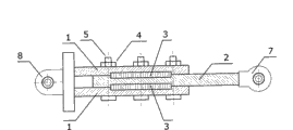
Fig. 5 embodiment shearing type lead damper constructional drawing
The hysteresis loop of Fig. 6 embodiment shearing type lead damper
Among the figure: 1, cover plate, 2, sliding panel, 3, shear lead, 4, locking nut, 5, screw rod, 6, shear lead block, 7, connect the hinge head, 8, band hinge end plate.
The specific embodiment
Below in conjunction with embodiment the utility model is further specified.
Shearing type lead damper as shown in Figure 5, include up and down two cover plates 1, sliding panel 2, two cover plates 1 are buckled in respectively on two surfaces up and down of sliding panel 2, on each contact surface of two cover plates 1 and sliding panel 2, all have a groove, and four groove location are relative, measure-alike, form two cavitys up and down, will shear lead 3 and directly be embedded in these two cavitys.Several screw rods 5 are passed two cover plates 1,, fix two cover plates 1 and be sandwiched in two sliding panel 2 and shearing leads 3 between the cover plate 1 by locking nut 4 tie down screws 5.Two cover plates 1 weld together with band hinge end plate 8, and sliding panel 2 cuts with scissors 7 and welds with being connected.
The present embodiment shearing type lead damper in the syndeton of having simplified lead and cover plate, makes its hysteresis performance consistent with the property retention of conventional shearing lead damper hysteresis, Figure 6 shows that the hysteresis loop of present embodiment shearing type lead damper.
Claims (1)
1, shearing type lead damper, include two cover plates (1), sliding panel (2) up and down, it is characterized in that: two cover plates (1) are buckled in respectively on two surfaces up and down of sliding panel (2), on each contact surface of two cover plates (1) and sliding panel (2), all have a groove, and four groove location are relative, measure-alike, form two cavitys up and down; In two cavitys, respectively embed a shearing lead (3) identical with cavity size; Screw rod (5) passes two cover plates (1), by locking nut (4) tie down screw (5), fixes two cover plates (1) and is sandwiched in the sliding panel (2) between two cover plates (1) and shears lead (3).
Priority Applications (1)
| Application Number | Priority Date | Filing Date | Title |
|---|---|---|---|
| CNU2008200788787U CN201155155Y (en) | 2008-02-01 | 2008-02-01 | Shearing -type lead damper |
Applications Claiming Priority (1)
| Application Number | Priority Date | Filing Date | Title |
|---|---|---|---|
| CNU2008200788787U CN201155155Y (en) | 2008-02-01 | 2008-02-01 | Shearing -type lead damper |
Publications (1)
| Publication Number | Publication Date |
|---|---|
| CN201155155Y true CN201155155Y (en) | 2008-11-26 |
Family
ID=40102940
Family Applications (1)
| Application Number | Title | Priority Date | Filing Date |
|---|---|---|---|
| CNU2008200788787U Expired - Fee Related CN201155155Y (en) | 2008-02-01 | 2008-02-01 | Shearing -type lead damper |
Country Status (1)
| Country | Link |
|---|---|
| CN (1) | CN201155155Y (en) |
Cited By (3)
| Publication number | Priority date | Publication date | Assignee | Title |
|---|---|---|---|---|
| CN104947830A (en) * | 2015-07-29 | 2015-09-30 | 北京工业大学 | Laminated steel-lead support |
| CN104947829A (en) * | 2015-07-29 | 2015-09-30 | 北京工业大学 | Method for assembling laminated steel-lead bearing with prefabricated cutting lead plates |
| CN105178465A (en) * | 2015-07-29 | 2015-12-23 | 北京工业大学 | Method for assembling laminated steel-lead support adopting lead plates formed by in-situ pouring and cooling |
-
2008
- 2008-02-01 CN CNU2008200788787U patent/CN201155155Y/en not_active Expired - Fee Related
Cited By (5)
| Publication number | Priority date | Publication date | Assignee | Title |
|---|---|---|---|---|
| CN104947830A (en) * | 2015-07-29 | 2015-09-30 | 北京工业大学 | Laminated steel-lead support |
| CN104947829A (en) * | 2015-07-29 | 2015-09-30 | 北京工业大学 | Method for assembling laminated steel-lead bearing with prefabricated cutting lead plates |
| CN105178465A (en) * | 2015-07-29 | 2015-12-23 | 北京工业大学 | Method for assembling laminated steel-lead support adopting lead plates formed by in-situ pouring and cooling |
| CN105178465B (en) * | 2015-07-29 | 2017-07-04 | 北京工业大学 | Using the lamination steel lead bearing assemble method of in-site pouring cooling shaping stereotype |
| CN104947829B (en) * | 2015-07-29 | 2017-10-31 | 北京工业大学 | Using the lamination steel lead bearing assemble method of prefabricated cutting stereotype |
Similar Documents
| Publication | Publication Date | Title |
|---|---|---|
| CN101225679A (en) | Shearing type lead damper | |
| CN201155155Y (en) | Shearing -type lead damper | |
| CN201908371U (en) | Structure of lead shearing damper | |
| CN202265917U (en) | Multi-groove lead shear damper | |
| CN205369577U (en) | Metal shearing damper | |
| CN205857383U (en) | A kind of assembled timber structure X-shaped beam column energy dissipation node | |
| CN206302376U (en) | The fixed structure of solar panel | |
| CN102873712B (en) | Automatic punching device for lithium ion battery tabs | |
| CN215107264U (en) | Ribbed plastic formwork capable of being sawed at any time and spliced at any time | |
| CN211396060U (en) | Column end energy consumption device | |
| CN212822831U (en) | Conductor spacer fastener drilling equipment | |
| CN201933639U (en) | Large-stroke lead shear damper | |
| CN209468884U (en) | It is a kind of for being set with the integrated wall plate of inorganic heat insulation material | |
| CN209742120U (en) | Buckling-restrained shear type damper with strong energy consumption performance under three-dimensional stress condition | |
| CN112609857A (en) | Curved shear damper based on embedded metal framework high polymer material | |
| CN203394024U (en) | Solid plastic building template | |
| CN106013444A (en) | Assembled type wood structure X-shaped beam column energy dissipation joint | |
| CN206393835U (en) | A kind of construction stone brick cutter | |
| CN217871202U (en) | EPS module connecting piece with adjustable cavity size | |
| CN209781542U (en) | plate type series connection type shape memory alloy friction damper | |
| CN201738581U (en) | Connection structure of a large steel moulding plate | |
| CN219634015U (en) | Efficient punching device for furniture boards | |
| CN214983822U (en) | Wood-based double-layer dot matrix sandwich structure | |
| CN216921545U (en) | High gymnasium large steel construction of stability | |
| CN212627484U (en) | New forms of energy motor fixed subassembly |
Legal Events
| Date | Code | Title | Description |
|---|---|---|---|
| C14 | Grant of patent or utility model | ||
| GR01 | Patent grant | ||
| C17 | Cessation of patent right | ||
| CF01 | Termination of patent right due to non-payment of annual fee |
Granted publication date: 20081126 Termination date: 20120201 |