Slewing supporting device for array type solar light-heat power-generation collecting device
(1) technical field
The utility model relates to a kind of slewing supporting device, particularly a kind ofly can regulate the solar tracking slewing supporting device of solar collector angle according to sunlight.
(2) background technology
At present, fuel energy day is becoming tight, and has become a kind of worldwide problem.It is predicted, world population will increase to 8,900,000,000 the year two thousand fifty, energy demand when the time comes will be present 3 times, and regenerative resource will account for 50%, the regenerative resource supply will be 2 times of present global energy consumption the year two thousand fifty, coal can only provide 30~50% of total energy power consumption in the China energy consumption, and all the other 50~70% will lean on oil, natural gas, water power, nuclear power, biomass energy and other regenerative resource.Because petroleum resources, nuclear power and the waterpower resourses of China are all very limited, directly a large amount of biomass burnings can also will be eliminated gradually, therefore, solar energy is as green, pollution-free, the permanent energy cheaply, not only, more be applicable to the mountain area that has inconvenient traffic, wasteland and frontier defense that China is vast in territory applicable to each building.Solar light-heat power-generation is a kind of clean energy resource of complete zero-emission, also be a kind of real energy near sizable application, government and business circles then are hopeful progressively to realize in China in the near future the fine ideal of " sunlight everywhere " everywhere fully if can pay attention to solar energy power generating as paying attention to nuclear energy.
Because the earth is an ellipse around the track of sun revolution, with regard to the Northern Hemisphere, winter, the earth was in the curved section recently of this circular orbit, and is near from the sun, summer, the earth was in far away day curved section of this circular orbit, far away from the sun, and winter is closely colder than the summer from the sun, tracing it to its cause is to be winter the cause of the sun oblique fire earth, time in summer, all there is sunlight direct projection chance tropic of cancer areas to the south, and this suffices to show that the sunlight direct projection penetrated object, and being penetrated object than oblique fire, the heat energy that obtains more more.But the slewing supporting device of present array type solar TRT is only with single coordinate direction solar tracking revolution, can only adjust the longitude angle of solar collector, can not adjust the latitude angle of solar collector, thereby can not guarantee farthest to obtain solar energy, and traditional solar energy light heat generator also only rests on the small-scale scope of separate unit, also is single small-scale generating.
(3) utility model content
The purpose of this utility model provides a kind of slewing supporting device for array type solar light-heat power-generation collecting device, solve traditional slewing supporting device only with single coordinate direction solar tracking revolution, can only adjust the longitude angle of solar collector, the latitude angle of solar collector can not be adjusted, the technical problem of solar energy can not be farthest obtained; And solve the problem that traditional solar energy light heat generator also only rests on the small-scale scope of separate unit.
For achieving the above object, the utility model adopts following technical scheme:
A kind of slewing supporting device for array type solar light-heat power-generation collecting device, be provided with solar collector 1 above the revolving dial 2, connect a circle supporting track 10 and a circle frictional drive guide rail 15 below the revolving dial 2, supporting track 10 is by 5 supportings of carrying support wheel, frictional drive guide rail 15 is connected with driving mechanism 4, driving mechanism 4 comprises frequency control motor 4.1, reductor 4.2, main friction pulley 4.3 and auxiliary friction pulley 4.4, it is characterized in that:
Solar collector 1 is fixedlyed connected with an end of swing arm 8, and the middle part of swing arm 8 and jib 7 are hinged, and the push rod of the other end of swing arm 8 and luffing driving mechanism 9 is hinged.
Carrying support wheel 5 is supported on the bearing spider 6, and on the frame 11 below the track of supporting track 10 is evenly distributed on supporting track, the outside of supporting track 10, on supporting track 10 lower wing plates, be equipped with the anti-roller 12 that topples, the pedestal of the anti-roller 12 that topples is connected with the anti-roller support 13 that topples, and the lower end of the anti-roller support 13 that topples and bearing spider 6 are fixing.
The revolving dial 2 following positioning tubes 3.1 that are provided with at the middle part, be provided with a delineation position roller 3.2 near positioning tube 3.1 peripheries, the turning rolls 3.3 that supports positioning roller is connected with positioning seat 3.4, and positioning seat 3.4 is fixed on the frame 11 by bolt 3.5, forms tracks positioned mechanism 3.
Above-mentioned solar collector is distributed on the revolving dial with array.
The swing arm 8 of the push rod of above-mentioned luffing driving mechanism 9 and two or two above solar collectors is hinged.
Above-mentioned revolving dial 2 is that radial beam and table top are linked in sequence above the steel truss by the latticed steel truss of shaped steel welding.
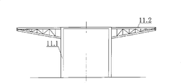
Above-mentioned frame 11 can be made up of an overhead strut 11.1 and an annular dish 11.2, and the main couple of an annular dish 11.2 is radial.
As the further optimized technical scheme of the utility model: the both sides of above-mentioned frictional drive guide rail 15 are equipped with outer dust ring 16 and interior dust ring 18, and interior dust ring 18 is supported by supporting leg 14, is with dust cover 17 outside driving mechanism 4.
Compared with prior art the utlity model has following characteristics and beneficial effect:
1, the utility model with the solar collector array in the revolution supporting mechanism on, drive solar collector with revolving dial, center on the center of circle rotation of revolving dial self with the angular speed that changes each daytime 0.5, promptly turn round synchronously with the rotation of the earth, simultaneously, utilize the gatherer jib to adjust the longitude angle, utilize the swing arm of collector jib lubbing mechanism push-and-pull solar collector to adjust the latitude angle, the collector jib lubbing mechanism 9 of solar collector can be with the angle of solar latitude angle adjustment solar collector, and relatively the horizontal line inclination angle is identical with the sun to make the angle of latitude of solar collector.So not only adjusted the longitude angle of solar collector, also adjusted the latitude angle simultaneously, make the revolution longitude and latitude angle and the earth rotation of solar collector, the angle speed of the sun is synchronous, always directly to the sun, follow the direct projection of the sun all the time from sun to sun, as the sunflower disk commentaries on classics neck solar tracking of sunflower, reach the effect of two-way solar tracking, obtained solar thermal energy to greatest extent.Though the utility model is adjusted angle and is wanted power consumption, array the utility model of 45 meters of diameters for example, 120 tons of solar collector and revolving dial gross weights, only need drive by two 0.75 kilowatt motors, the photo-thermal power generation amount that increases can reach more than 22 times of motor, so the utility model has improved the photo-thermal power generation ability of solar collector greatly, on the area of existing solar energy heat trap, must farthest obtain solar energy, improved photo-thermal efficient.
2. revolving dial and solar collector are formed revolving body, compare mechanical driving device by motor and big retarding that friction drive drags thereof, drag the revolving body revolution, for realizing making solar energy heat trap solar tracking revolution, the utmost point slow speed that changes each daytime 0.5 to the solar energy heat trap by the high revolution of motor, be by secondary planet spindle wheel swinging reducer serial connection, the overall deceleration of finishing by friction drive at last.Motor via reducer drives main friction pulley and rotates, by adjusting the distance between main friction pulley and the driven friction pulley, make master and slave friction pulley clamp the frictional drive guide rail, friction extensible guide and platform cyclic structure fuse, the drive platform rotates, and promptly forms friction driven system.Friction pulley compensation mechanism, friction pulley synchronous follow-up mechanism can make friction pulley clamp friction extensible guide at any time, and can be with the same moved further of friction extensible guide, guarantee that on circumference every frictional force equates, do not have throw switch, skidding, remove daily adjustment from and operate steadily.
3, the utility model is provided with tracks positioned mechanism, can prevent that in-plane displancement from appearring in revolving dial in rotary course, also can satisfy the requirement that energy transmits.
4, the utility model has also been considered seismic fortification intensity, wind load and snow load, in rail supported mechanism one side the anti-mechanism that topples is set, and can prevent that solar collector and revolving dial from toppling.So the utility model makes that the solar energy heat trap can be realized array, the heat generating is adopted in solar tracking on a large scale, has improved the collecting efficiency of solar collector 1 greatly.
(4) description of drawings
The utility model is described in more detail below in conjunction with accompanying drawing.
Fig. 1 is a structural representation of the present utility model.
Fig. 2 be solar collector with revolving dial between be connected embodiment one schematic diagram.
Fig. 3 is the enlarged diagram at I place among Fig. 1.
Fig. 4 is the structural representation of tracks positioned mechanism.
Fig. 5 is the A-A generalized section of Fig. 4.
Fig. 6 is the schematic diagram that the frictional drive guide rail is connected with driving mechanism.
Fig. 7 is the enlarged diagram at II place among Fig. 1.
Fig. 8 is the schematic diagram of frame.
Fig. 9 is the vertical view of Fig. 8.
Figure 10 be solar collector with revolving dial between be connected embodiment two schematic diagrames.
Reference numeral: 1-solar collector, the 2-revolving dial, 3-tracks positioned mechanism, 3.1-positioning tube, 3.2-positioning roller, 3.3-turning rolls, 3.4-positioning seat, 3.5-bolt, the 4-driving mechanism, 4.1-frequency control motor, 4.2-reductor, 4.3-main friction pulley, 4.4-auxiliary friction pulley, 5-carries support wheel, the 6-bearing spider, the 7-jib, the 8-swing arm, 9-luffing driving mechanism, the 10-supporting track, the 11-frame, 11.1-overhead strut, a 11.2-annular dish, the anti-roller that topples of 12-, the anti-roller support that topples of 13-, the 14-supporting leg, 15-frictional drive guide rail, the outer dust ring of 16-, the 17-dust cover, dust ring in the 18-.
(5) specific embodiment
Embodiment is referring to shown in Figure 1, this slewing supporting device for array type solar light-heat power-generation collecting device, and solar collector 1 is arranged on the revolving dial 2 with array.Revolving dial 2 drives rotation by frequency control motor and friction pulley transmission mechanism.Connect a circle supporting track 10 and a circle frictional drive guide rail 15 below the revolving dial 2, supporting track 10 is by 5 supportings of carrying support wheel, and frictional drive guide rail 15 is connected with driving mechanism 4.Revolving dial 2 is that radial beam and table top are linked in sequence above the steel truss by the latticed steel truss of shaped steel welding.
Referring to Fig. 8, Fig. 9, frame 11 is made up of an overhead strut 11.1 and an annular dish 11.2, and the main couple of an annular dish 11.2 is radial.
Referring to Fig. 2, solar collector 1 is fixedlyed connected with an end of swing arm 8, and the middle part of swing arm 8 and jib 7 are hinged, and the push rod of the other end of swing arm 8 and luffing driving mechanism 9 is hinged.The use of can connecting of luffing driving mechanism also can reduce quantity.The push rod of above-mentioned luffing driving mechanism 9 can be hinged with the swing arm 8 of two or two above solar collectors, and the pin joint position can be located in the triangle jib, and referring to Figure 10, the pin joint position also can be located at triangle jib upper end.Revolving dial is dragged the angular speed that changes with each daytime 0.5 around the axle center rotation of system location by frequency control motor and friction pulley transmission mechanism, promptly synchronous with the rotation of the earth, luffing driving mechanism 9 can make solar collector 1 directly adopt heat to the sun according to the angle of solar latitude angle adjustment solar collector 1.
Referring to Fig. 3, carrying support wheel 5 is supported on the bearing spider 6, and on the frame 11 below the track of supporting track 10 is evenly distributed on supporting track, the outside of supporting track 10, be equipped with the anti-roller 12 that topples on supporting track 10 lower wing plates, the pedestal of the anti-roller 12 that topples is connected with the anti-roller support 13 that topples, and prevents toppling roller support 13 for L shaped, its lower end and bearing spider 6 are fixing, and bearing spider 6 is the adjustable height bearing.
Referring to Fig. 4-5, can be provided with detent mechanism in the axle center accurately around the axial line rotation in order to ensure revolving dial, can make the revolving dial off-centring less than 5 millimeters.The revolving dial 2 following positioning tubes 3.1 that are provided with at the middle part, be provided with a delineation position roller 3.2 near positioning tube 3.1 peripheries, the turning rolls 3.3 that supports positioning roller is connected with positioning seat 3.4, positioning seat 3.4 is fixed on the frame 11 by bolt 3.5, form tracks positioned mechanism 3, the height of positioning seat 3.4 can be regulated.
Referring to Fig. 6-7, driving mechanism 4 drags the frictional drive guide rail and finishes the revolving dial rotation.Driving mechanism 4 comprises frequency control motor 4.1, reductor 4.2, main friction pulley 4.3, auxiliary friction pulley 4.4, friction pulley follower 4.5, friction pulley clamping force compensation mechanism 4.6 and electric control system.Drive main friction pulley with frequency control motor by reductor and rotate,, make master and slave friction pulley clamp the frictional drive guide rail by adjusting the distance between main friction pulley and the driven friction pulley.Friction pulley compensation mechanism, friction pulley synchronous follow-up mechanism can make friction pulley clamp friction extensible guide at any time, and can be with the same moved further of friction extensible guide, guarantee that on circumference every frictional force equates, do not have throw switch, skidding, remove daily adjustment from and operate steadily.Change~500 frequency modulation motors that change, total reduction ratio 20000~30000 if select synchronous revolutions per minute 1450 for use.The Frequency Converter Control motor travels at the uniform speed.In the rotary speed scope of application, adjust electric machine frequency by frequency converter, can change the platform rotating speed.Speed governing is evenly level and smooth, no dead band.Delayed startup device, the slow stop device that slows down make turntable acceleration and deceleration when starting and stopping steady, do not have and impact.Adjust frequency converter, can change the rotating speed of revolving dial.Driving mechanism 4 comprise frequency control motor.The electric control system of driving mechanism is contained in the frequency control motor on the main frame body by the switch board that places master-control room, connects compositions such as lead.Switch board is made up of switch, voltmeter, contactor, phase failure protector, the time relay, frequency converter, overheat protector, fuse, indicator lamp etc.
Because the solar energy light heat generator arranged in arrays is on the bigger revolving dial of diameter, the utility model has been considered seismic fortification intensity, wind load and the snow load of user locality.Be provided with anti-travel fatigue mechanism.Frictional drive guide rail 15 is made up of the more piece arc track, and its both sides are equipped with outer dust ring 16 and interior dust ring 18, and interior dust ring 18 is supported by supporting leg 14, is with dust cover 17 outside driving mechanism 4, helps guaranteeing the normal operation and the kinematic accuracy of revolving dial.