CN201141663Y - Photocatalyst module and air conditioning system comprising same - Google Patents
Photocatalyst module and air conditioning system comprising same Download PDFInfo
- Publication number
- CN201141663Y CN201141663Y CNU2007201834190U CN200720183419U CN201141663Y CN 201141663 Y CN201141663 Y CN 201141663Y CN U2007201834190 U CNU2007201834190 U CN U2007201834190U CN 200720183419 U CN200720183419 U CN 200720183419U CN 201141663 Y CN201141663 Y CN 201141663Y
- Authority
- CN
- China
- Prior art keywords
- photocatalyst
- module
- light
- conditioning system
- photocatalyst filter
- Prior art date
- Legal status (The legal status is an assumption and is not a legal conclusion. Google has not performed a legal analysis and makes no representation as to the accuracy of the status listed.)
- Expired - Fee Related
Links
- 239000011941 photocatalyst Substances 0.000 title claims abstract description 107
- 238000004378 air conditioning Methods 0.000 title claims abstract description 24
- 238000001816 cooling Methods 0.000 claims abstract description 8
- 239000000463 material Substances 0.000 claims description 9
- NIXOWILDQLNWCW-UHFFFAOYSA-N acrylic acid group Chemical group C(C=C)(=O)O NIXOWILDQLNWCW-UHFFFAOYSA-N 0.000 claims description 4
- 229920000642 polymer Polymers 0.000 claims description 2
- 239000004020 conductor Substances 0.000 abstract description 2
- -1 acryl Chemical group 0.000 abstract 1
- 238000010586 diagram Methods 0.000 description 6
- 239000000126 substance Substances 0.000 description 4
- 238000006243 chemical reaction Methods 0.000 description 2
- 241000894006 Bacteria Species 0.000 description 1
- 241000700605 Viruses Species 0.000 description 1
- 238000003915 air pollution Methods 0.000 description 1
- 230000000694 effects Effects 0.000 description 1
- 239000000835 fiber Substances 0.000 description 1
- 238000000034 method Methods 0.000 description 1
- 231100000614 poison Toxicity 0.000 description 1
- 239000003440 toxic substance Substances 0.000 description 1
Images


Classifications
-
- Y—GENERAL TAGGING OF NEW TECHNOLOGICAL DEVELOPMENTS; GENERAL TAGGING OF CROSS-SECTIONAL TECHNOLOGIES SPANNING OVER SEVERAL SECTIONS OF THE IPC; TECHNICAL SUBJECTS COVERED BY FORMER USPC CROSS-REFERENCE ART COLLECTIONS [XRACs] AND DIGESTS
- Y02—TECHNOLOGIES OR APPLICATIONS FOR MITIGATION OR ADAPTATION AGAINST CLIMATE CHANGE
- Y02A—TECHNOLOGIES FOR ADAPTATION TO CLIMATE CHANGE
- Y02A50/00—TECHNOLOGIES FOR ADAPTATION TO CLIMATE CHANGE in human health protection, e.g. against extreme weather
- Y02A50/20—Air quality improvement or preservation, e.g. vehicle emission control or emission reduction by using catalytic converters
Landscapes
- Disinfection, Sterilisation Or Deodorisation Of Air (AREA)
Abstract
Description
技术领域 technical field
本实用新型涉及一种提供一种光触媒模块与包含此光触媒模块的空调系统,特别涉及一种用于消除空气中有害物质的光触媒模块与其空调系统。The utility model relates to a photocatalyst module and an air-conditioning system including the photocatalyst module, in particular to a photocatalyst module for eliminating harmful substances in the air and an air-conditioning system thereof.
背景技术 Background technique
随着工业的进步与发达,空气污染日益严重。为了维持居家的空气品质,一般的空调设备都具有空气净化器。目前的空气净化器大多包含有光触媒模块,此光触媒模块利用紫外光来照射光触媒,使光触媒发生化学反应,以消除空气中对人体有害的物质。With the progress and development of industry, air pollution is becoming more and more serious. In order to maintain the air quality at home, general air conditioners are equipped with air purifiers. Most of the current air purifiers include a photocatalyst module, which uses ultraviolet light to irradiate the photocatalyst, causing the photocatalyst to undergo a chemical reaction to eliminate harmful substances in the air.
请参照图1,为现有光触媒模块10的结构示意图。光触媒模块10包含有冷阴极莹光灯管(CCFL)12和光触媒滤网14,其中光触媒滤网14为涂布有光触媒的纤维。当冷阴极莹光灯管12发射紫外线至光触媒滤网14时,光触媒滤网14中的光触媒会发生化学反应而产生氢氧自由基。氢氧自由基是极具分解能力的分子,能分解各种有害物质,例如细菌、病毒等...。Please refer to FIG. 1 , which is a schematic structural diagram of a
然而,因为光触媒模块10的照射面无法均匀广泛,因此,光触媒滤网14上可能会有未被紫外光照射到的死角。另外,冷阴极莹光灯管所占据的体积过大,且含有有毒物质,因此光触媒模块10不但体积庞大且容易污染环境。However, since the irradiated surface of the
因此需要提供一种新的光触媒模块,不但具有均匀的照射面,还具有更小的体积,以及不会污染环境。Therefore, it is necessary to provide a new photocatalyst module, which not only has a uniform irradiated surface, but also has a smaller volume and does not pollute the environment.
发明内容 Contents of the invention
本实用新型的一目的在于提供一种包含导光物体的光触媒模块。An object of the present invention is to provide a photocatalyst module including a light guiding object.
本实用新型的另一目的在于提供一种包含此光触媒模块的空调系统。Another object of the present invention is to provide an air conditioning system including the photocatalyst module.
根据本实用新型的一实施例,此光触媒模块至少包含光触媒滤网和数个第一发光二极管。光触媒滤网以导光材料所制成,例如:压克力。第一发光二极管邻设于光触媒滤网的第一侧面,用以发射紫外光至光触媒滤网。According to an embodiment of the present invention, the photocatalyst module at least includes a photocatalyst filter and several first light emitting diodes. The photocatalyst filter is made of light-guiding materials, such as acrylic. The first light-emitting diode is adjacent to the first side of the photocatalyst filter for emitting ultraviolet light to the photocatalyst filter.
根据本实用新型的另一实施例,此光触媒模块更包含数个第二发光二极管。第二发光二极管用以发射另一紫外光至光触媒滤网,并邻设于光触媒滤网的第二侧面。According to another embodiment of the present invention, the photocatalyst module further includes a plurality of second light emitting diodes. The second light-emitting diode is used for emitting another ultraviolet light to the photocatalyst filter, and is adjacent to the second side of the photocatalyst filter.
根据本实用新型的再一实施例,提供一种空调系统。此空调系统至少包含光触媒模块和风扇模块。风扇模块,用以通过光触媒模块来吸入空气至空调系统。光触媒模块至少包含光触媒滤网和数个发光二极管,其中该光触媒滤网为一导光材料所制成,发光二极管邻设于光触媒滤网的一侧面。According to yet another embodiment of the present utility model, an air conditioning system is provided. The air conditioning system at least includes a photocatalyst module and a fan module. The fan module is used to suck air into the air conditioning system through the photocatalyst module. The photocatalyst module at least includes a photocatalyst filter net and several light-emitting diodes, wherein the photocatalyst filter net is made of a light-conducting material, and the light-emitting diodes are adjacent to one side of the photocatalyst filter net.
综合以上所述,本实用新型的功效在于,光触媒模块可减少紫外光照的死角,提升光触媒的利用率,且更具有体积小,不具污染源等优点。Based on the above, the effect of the utility model is that the photocatalyst module can reduce the dead angle of ultraviolet light, improve the utilization rate of the photocatalyst, and has the advantages of small size and no pollution source.
以下结合附图和具体实施例对本实用新型进行详细描述,但不作为对本实用新型的限定。The utility model will be described in detail below in conjunction with the accompanying drawings and specific embodiments, but not as a limitation of the utility model.
附图说明 Description of drawings
图1为现有光触媒模块的结构示意图;Fig. 1 is the structural representation of existing photocatalyst module;
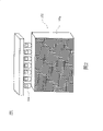
图2为本实用新型的第一实施例的光触媒模块的结构示意图;Fig. 2 is the structural representation of the photocatalyst module of the first embodiment of the utility model;
图3为本实用新型的第二实施例的光触媒模块的结构示意图;Fig. 3 is the structural representation of the photocatalyst module of the second embodiment of the present utility model;
图4为本实用新型的第四实施例的空调系统的结构示意图;Fig. 4 is the structural representation of the air-conditioning system of the 4th embodiment of the utility model;
图5为本实用新型的第五实施例的空调系统的结构示意图。Fig. 5 is a schematic structural diagram of an air conditioning system according to a fifth embodiment of the present invention.
其中,附图标记Among them, reference signs
10:光触媒模块 12:冷阴极莹光灯管10: Photocatalyst module 12: Cold cathode fluorescent lamp
14:光触媒滤网 100:光触媒模块14: Photocatalyst filter 100: Photocatalyst module
102:光触媒滤网 102a:侧面102:
102b:侧面 102c:表面102b:
102d:表面 104:发光二极管102d: surface 104: light emitting diode
200:光触媒模块 204:发光二极管200: photocatalyst module 204: light emitting diode
400:空调系统 410:风扇模块400: Air conditioning system 410: Fan module
420:空气 500:空调系统420: Air 500: Air Conditioning System
502:冷却模块502: cooling module
具体实施方式Detailed ways
请参照图2,其为本实用新型的第一实施例的光触媒模块100的结构示意图。光触媒模块100至少包含光触媒滤网102和数个发光二极管104,其中光触媒滤网102以导光材料所制成。此导光材料可为高分子聚合物,例如:压克力。发光二极管104邻设于光触媒滤网102的一侧面102a,并用以发射紫外光至光触媒滤网102。由于光触媒滤网102由导光材料所组成,因此当紫外光照射到光触媒滤网102后,便会均匀分散至光触媒滤网102的每个部份,减少光照的死角。另外,光触媒模块100以发光二极管来代替现有光触媒模块中的冷阴极莹光灯管,因此光触媒模块100的体积可较现有光触媒模块为小,且不会污染环境。Please refer to FIG. 2 , which is a schematic structural diagram of the
请参照图3,其为本实用新型的第二实施例的光触媒模块200的结构示意图。光触媒模块200类似于光触媒模块100,但不同之处在于光触媒模块100更包含了数个发光二极管204。发光二极管204邻设于光触媒滤网102的另一侧面102b,侧面102b与侧面102a相邻。利用发光二极管104和204来分别从水平和垂直方向发射紫外光至光触媒滤网102,可进一步减少光照的死角。Please refer to FIG. 3 , which is a schematic structural diagram of a
值得一提的是,在本实用新型的第二实施例中,空气可由表面102c进入光触媒滤网102,再从表面102d离开光触媒滤网102,其中表面102c相对于表面102d,而侧面102b和侧面102a皆与表面102c和表面102d相邻。It is worth mentioning that, in the second embodiment of the present utility model, the air can enter the
请参照图4,其为本实用新型的第四实施例的空调系统400的结构示意图。空调系统400至少包含:光触媒模块100和风扇模块410。风扇模块410用以抽取空气420来流过光触媒模块100,以减少空气中的有害物质。Please refer to FIG. 4 , which is a schematic structural diagram of an
请参照图5,其为本实用新型的第五实施例的空调系统500的结构示意图。空调系统500类似于空调系统400,但不同之处在于空调系统500更包含冷却模块502。冷却模块502用以将光触媒模块100所制造的干净空气降温。因此空调系统500可例如为冷气机。Please refer to FIG. 5 , which is a schematic structural diagram of an
综合以上所述,本实用新型的光触媒模块可减少紫外光照的死角,提升光触媒的利用率,且更具有体积小,不具污染源等优点。Based on the above, the photocatalyst module of the present invention can reduce the dead angle of ultraviolet light, improve the utilization rate of photocatalyst, and has the advantages of small size and no pollution source.
当然,本实用新型还可有其它多种实施例,在不背离本实用新型精神及其实质的情况下,熟悉本领域的技术人员当可根据本实用新型作出各种相应的改变和变形,但这些相应的改变和变形都应属于本实用新型所附的权利要求的保护范围。Of course, the utility model can also have other various embodiments, and those skilled in the art can make various corresponding changes and deformations according to the utility model without departing from the spirit and essence of the utility model, but These corresponding changes and deformations should all belong to the protection scope of the appended claims of the present utility model.
Claims (10)
Priority Applications (1)
| Application Number | Priority Date | Filing Date | Title |
|---|---|---|---|
| CNU2007201834190U CN201141663Y (en) | 2007-10-16 | 2007-10-16 | Photocatalyst module and air conditioning system comprising same |
Applications Claiming Priority (1)
| Application Number | Priority Date | Filing Date | Title |
|---|---|---|---|
| CNU2007201834190U CN201141663Y (en) | 2007-10-16 | 2007-10-16 | Photocatalyst module and air conditioning system comprising same |
Publications (1)
| Publication Number | Publication Date |
|---|---|
| CN201141663Y true CN201141663Y (en) | 2008-10-29 |
Family
ID=40069374
Family Applications (1)
| Application Number | Title | Priority Date | Filing Date |
|---|---|---|---|
| CNU2007201834190U Expired - Fee Related CN201141663Y (en) | 2007-10-16 | 2007-10-16 | Photocatalyst module and air conditioning system comprising same |
Country Status (1)
| Country | Link |
|---|---|
| CN (1) | CN201141663Y (en) |
Cited By (1)
| Publication number | Priority date | Publication date | Assignee | Title |
|---|---|---|---|---|
| US8911670B2 (en) | 2011-08-03 | 2014-12-16 | Honeywell International Inc. | LED activated photocatalyst air filter |
-
2007
- 2007-10-16 CN CNU2007201834190U patent/CN201141663Y/en not_active Expired - Fee Related
Cited By (1)
| Publication number | Priority date | Publication date | Assignee | Title |
|---|---|---|---|---|
| US8911670B2 (en) | 2011-08-03 | 2014-12-16 | Honeywell International Inc. | LED activated photocatalyst air filter |
Similar Documents
| Publication | Publication Date | Title |
|---|---|---|
| CN204285671U (en) | Double-loop indoor fresh air supply and circulation treatment system | |
| CN102974214A (en) | Photocatalyst air purification device | |
| Shamim et al. | Review of component designs for post-COVID-19 HVAC systems: possibilities and challenges | |
| CN101078543A (en) | Sterilization processing device dedicated for blast pipe | |
| CN204943819U (en) | Luminous lamp with air cleaning function | |
| CN201141663Y (en) | Photocatalyst module and air conditioning system comprising same | |
| CN103480274A (en) | Wall-hanging photocatalytic air purifier | |
| CN106076088A (en) | VOC gas handling system | |
| CN2821447Y (en) | Light catalytic air purifier | |
| Chen | Enhancing air quality for embedded hospital germicidal lamps | |
| TWM329442U (en) | Photocatalyst module and air-conditioning system including the same | |
| CN1651098A (en) | Photocatalyst air cleaning device | |
| CN106881020B (en) | Photocatalytic purification device | |
| CN211838032U (en) | Remote time control superclean bench | |
| CN205965499U (en) | Biological enzyme device and have VOC gas handling system of this biological enzyme device | |
| CN104456770A (en) | Air purifier | |
| CN205634975U (en) | Water overflows formula light catalytic oxidation sewage treatment plant | |
| CN214249866U (en) | Purification components and air conditioners | |
| CN201223576Y (en) | Air clarifying device | |
| CN222219658U (en) | Ecological toxicology test workbench | |
| CN216620161U (en) | An ultra-thin double lamp board illumination air purifier | |
| JP2011133140A (en) | Air cleaning device and air cleaning system for clean room using visible light responsive catalyst | |
| NL1044260B1 (en) | Air cleaning apparatus | |
| CN2636134Y (en) | Air purifier for central air conditioner | |
| CN207307582U (en) | A kind of exhaust-gas treatment UV photocatalytic oxidation devices |
Legal Events
| Date | Code | Title | Description |
|---|---|---|---|
| C14 | Grant of patent or utility model | ||
| GR01 | Patent grant | ||
| CF01 | Termination of patent right due to non-payment of annual fee |
Granted publication date: 20081029 Termination date: 20141016 |
|
| EXPY | Termination of patent right or utility model |