CN201124689Y - Multipurpose compass - Google Patents
Multipurpose compass Download PDFInfo
- Publication number
- CN201124689Y CN201124689Y CNU2007200416756U CN200720041675U CN201124689Y CN 201124689 Y CN201124689 Y CN 201124689Y CN U2007200416756 U CNU2007200416756 U CN U2007200416756U CN 200720041675 U CN200720041675 U CN 200720041675U CN 201124689 Y CN201124689 Y CN 201124689Y
- Authority
- CN
- China
- Prior art keywords
- rotating shaft
- support bar
- swingle
- dial
- multipurpose
- Prior art date
- Legal status (The legal status is an assumption and is not a legal conclusion. Google has not performed a legal analysis and makes no representation as to the accuracy of the status listed.)
- Expired - Fee Related
Links
Images

Landscapes
- Length-Measuring Instruments Using Mechanical Means (AREA)
- Drawing Aids And Blackboards (AREA)
Abstract
The utility model discloses a multipurpose compass. The multipurpose compass comprises a support rod and a rotating rod, which are overlapped to each other, and a rotating shaft penetrating the upper parts of the two rods. The support rod and the rotating rod share and rotate around the rotating shaft. A round graduated disk is arranged on the surface of the support rod, which is close to the rotating rod. The graduated disk takes the rotating shaft as the circle center, and the diameter of the graduated disk is slightly smaller than the width of the support rod where the graduated disk is located. One end of the rotating rod in the upper part of the rotating shaft serves as a reading indicator tip, and the linear distance between the tip of the rotating rod and the rotating shaft is equal to the semi-diameter of the graduated disk. The multipurpose compass has the advantages of smart design, easy use, integrated functions of the compass, straight ruler and angle gauge, low cost, and suitability for industrialized production.
Description
Technical field:
The utility model relates to a kind of drawing instrument, relates in particular to a kind of multipurpose compasses.
Background technology:
No matter be that the teacher is in teaching process, still the student is in learning process, all usually to use compasses, ruler, protractor etc., and these instruments function singleness often at present, to constantly change instrument in the drawing course, concerning the teacher, waste instructional blocks of time, concerning the student, wasted valuable learning time especially.Moreover China must consume a large amount of timber because of making teaching aids such as ruler, set square, protractor, compasses every year, also is the waste to resource.
The utility model content:
The purpose of this utility model is to improve at the problem that prior art exists.Design a kind of multipurpose compasses, it can use as compasses, also can use as ruler, set square, protractor.
The technical solution of the utility model is achieved in that
The multipurpose compasses, comprise overlapped support bar and swingle, and the rotating shaft of passing their top, support bar and swingle can rotate around common rotating shaft, be posted by at support bar on the one side of swingle and be carved with circular scale, this dial is the center of circle with the rotating shaft, and diameter is less than the width of the support bar of this dial position; The end of swingle on rotating shaft top is the reading indication end, and its summit equals the radius of dial to the air line distance of rotating shaft.
The circumference of described dial is provided with scale, and circumference is divided into 360 parts, is the scale starting point directly over the rotating shaft.
The lateral surface of described support bar is provided with the length scale.
Beneficial effect: after adopting this kind structure, when drawing, can use compasses normally to draw circle, when the line segment of the slotted line segment length or the Len req that draws, support bar can be used as ruler and uses; These compasses also can be used to the measuring angle and the required angle of drawing simultaneously.The utility model is rational in infrastructure, and is convenient and practical, integrates multiple function.
Description of drawings:
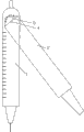
Fig. 1 is the front view of the utility model support bar.
Fig. 2 is user mode figure of the present utility model.
Number in the figure: 1, support bar, 2, swingle, 3, dial, 4, rotating shaft, 5, the reading indication end.
Below in conjunction with the drawings and specific embodiments the utility model is described in further detail.
The specific embodiment:
Embodiment:
Referring to Fig. 1, Fig. 2, the multipurpose compasses of present embodiment, comprise overlapped support bar 1 and swingle 2, and the rotating shaft 4 of passing their top, support bar and swingle can rotate around common rotating shaft, position more than rotating shaft, the length of support bar is greater than swingle, be posted by at support bar on the one side of swingle and be carved with circular scale 3, this dial is the center of circle with the rotating shaft, and diameter is slightly less than the width of the support bar of this dial position, the circumference of dial is provided with scale, circumference is divided into 360 parts, and each part represents 1 °, 0 ° of point be arranged on rotating shaft directly over; Being positioned at the above part of rotating shaft on the swingle is reading indication end 5, and its summit equals the radius of dial to the air line distance of rotating shaft.In other words when compasses are closed, 0 ° position on the position positive alignment dial of swingle upper vertex.When the number of degrees at certain angle of requirement, rotating shaft is placed on the summit at angle, rotate the support bar and the swingle of compasses, side until two bars overlaps with the both sides at angle respectively, at this moment summit, reading indication end reading pointed is the number of degrees at this angle, and its principle is that vertical angles equate, the internal angles on the same side equates.In like manner, when angle that needs draw certain number of degrees, for example draw 30 ° angle, rotate compasses, making summit, reading indication end point to scale is 30 ° place, this moment, the formed angle in lower end of compasses two legs also was 30 °, drew two straight lines along two leg sides, and these two formed angles of straight line are exactly 30 ° angle.
The lateral surface of the support bar of compasses is provided with the length scale, when needs measure the length of certain line segment, a side that support bar is provided with scale leans against on the line segment, just can measure the length of this line segment according to line segment two-end-point reading pointed, in like manner, the line segment of certain length-specific if will draw, then support bar also can be used as ruler.
Claims (3)
1, multipurpose compasses, comprise overlapped support bar (1) and swingle (2), and the rotating shaft (4) of passing their top, support bar and swingle can rotate around common rotating shaft, it is characterized in that, be posted by at support bar on the one side of swingle and be carved with circular scale (3), this dial is the center of circle with the rotating shaft, and diameter is less than the width of the support bar of this dial position; The end of swingle on rotating shaft top is reading indication end (5), and its summit equals the radius of dial to the air line distance of rotating shaft.
2, multipurpose compasses according to claim 1 is characterized in that, the circumference of described dial (3) is provided with scale, and circumference is divided into 360 parts, are the scale starting point directly over the rotating shaft.
3, multipurpose compasses according to claim 1 is characterized in that, the lateral surface of described support bar (1) is provided with the length scale.
Priority Applications (1)
| Application Number | Priority Date | Filing Date | Title |
|---|---|---|---|
| CNU2007200416756U CN201124689Y (en) | 2007-11-28 | 2007-11-28 | Multipurpose compass |
Applications Claiming Priority (1)
| Application Number | Priority Date | Filing Date | Title |
|---|---|---|---|
| CNU2007200416756U CN201124689Y (en) | 2007-11-28 | 2007-11-28 | Multipurpose compass |
Publications (1)
| Publication Number | Publication Date |
|---|---|
| CN201124689Y true CN201124689Y (en) | 2008-10-01 |
Family
ID=39998104
Family Applications (1)
| Application Number | Title | Priority Date | Filing Date |
|---|---|---|---|
| CNU2007200416756U Expired - Fee Related CN201124689Y (en) | 2007-11-28 | 2007-11-28 | Multipurpose compass |
Country Status (1)
| Country | Link |
|---|---|
| CN (1) | CN201124689Y (en) |
-
2007
- 2007-11-28 CN CNU2007200416756U patent/CN201124689Y/en not_active Expired - Fee Related
Similar Documents
| Publication | Publication Date | Title |
|---|---|---|
| CN202144164U (en) | Straight ruler capable of measuring diameter | |
| CN201769555U (en) | Multifunctional mathematical ruler | |
| CN202439433U (en) | Teaching compass | |
| CN201124689Y (en) | Multipurpose compass | |
| CN201501217U (en) | Multi-functional plotting instrument | |
| CN205009840U (en) | Multi -functional double -deck chi | |
| CN201522798U (en) | Triangular gauge teaching aids | |
| CN203580444U (en) | Multifunctional drawing tool | |
| CN2933900Y (en) | Multifunctional folding ruler | |
| CN201970705U (en) | Multi-use teaching aid for classroom | |
| CN202293915U (en) | Angular bisector drawing instrument | |
| CN201931855U (en) | Multifunctional ruler | |
| CN205033805U (en) | Ruler for math graphing | |
| CN204404971U (en) | A kind of arc measuring instrument | |
| CN202293918U (en) | Multifunctional set square for teaching | |
| CN201998680U (en) | Ruler for clothing structural drafting | |
| CN202225636U (en) | Gauge combination | |
| CN202826859U (en) | Novel ruler | |
| CN202557105U (en) | Multifunctional mathematics teaching aid | |
| CN200975868Y (en) | Multifunctional protractor | |
| CN202911393U (en) | Compasses used for teaching | |
| CN202403631U (en) | Bidirectional readable protractor | |
| CN203249558U (en) | Protractor with high precision | |
| CN201989512U (en) | Plotting instrument | |
| CN201998681U (en) | Tool for clothing drafting |
Legal Events
| Date | Code | Title | Description |
|---|---|---|---|
| C14 | Grant of patent or utility model | ||
| GR01 | Patent grant | ||
| C19 | Lapse of patent right due to non-payment of the annual fee | ||
| CF01 | Termination of patent right due to non-payment of annual fee |