CN201121959Y - Intelligent energy-saving ventilating system of machine room - Google Patents
Intelligent energy-saving ventilating system of machine room Download PDFInfo
- Publication number
- CN201121959Y CN201121959Y CNU2007201958259U CN200720195825U CN201121959Y CN 201121959 Y CN201121959 Y CN 201121959Y CN U2007201958259 U CNU2007201958259 U CN U2007201958259U CN 200720195825 U CN200720195825 U CN 200720195825U CN 201121959 Y CN201121959 Y CN 201121959Y
- Authority
- CN
- China
- Prior art keywords
- air
- indoor
- machine room
- outdoor
- probe
- Prior art date
- Legal status (The legal status is an assumption and is not a legal conclusion. Google has not performed a legal analysis and makes no representation as to the accuracy of the status listed.)
- Expired - Fee Related
Links
Images


Abstract
The utility model discloses a machinery room intelligence energy conservation ventilation system, which comprises an air inlet passage and an air outlet passage which are respectively arranged on the wall of a machinery room, an air inlet device arranged in the air inlet passage, an air outlet device arranged in the air outlet passage, an outdoor probe and an indoor probe which can respectively detect the temperature indoors and outdoors, an air conditioning controller and a main controller, wherein, the main controller is respectively and electrically connected with the probes, the air inlet device, the air outlet device and the air conditioning controller in the machinery room. The indoor and outdoor temperature and the humidity values can be detected by collecting the information of the outdoor probe and the indoor probe, and the open and the close of the air conditioning controller, the air outlet device and the air inlet device can be controlled according to the difference of the indoor and outdoor temperature and the humidity. The machinery room intelligence energy conservation ventilation system can save the power used by the air conditioner in a communication machinery room, and effectively reduce the power consumption in the machinery room.
Description
Technical field
The utility model belongs to the automatic control technology field, relates to a kind of machine room intelligent energy-saving ventilation system.
Background technology
(standard No.: regulation GF014.95): general computer room temperature remains 22 ℃-26 ℃ according to China Telecom's regulations " communications equipment room environment energy condition (interim provision) "; Humidity remains 45%-75%; Cleanliness factor reaches the B level; Battery temp keeps 5 ℃-30 ℃.Current, mobile communication base station, unattended communication base station are taked totally enclosed machine room basically, because indoor power-supply device, transmitter, transmission equipment etc. all belong to the big pyrotoxin of caloric value, in order to ensure the reliable continuity work of communication equipment, its people's loss that minimizing brings because of communication failure or interruption, indoor conditions is generally all improved by air-conditioning system in present communications equipment room/base station, communication electronic equipment is more reasonably being moved under the humiture environment, guarantee operation stability of equipment.But along with telecommunication path network and user's continuous expansion, the excessive power consumption of business equipment has accounted for the very big part of its cost expenditure.
The utility model content
Technical problem to be solved in the utility model is at the prior art above shortcomings, provides a kind of and saves the communication machine room air conditioning electricity, effectively reduces the machine room intelligent energy-saving ventilation system of machine room energy consumption.
The technical scheme that solution the utility model technical problem is adopted is that this machine room intelligent energy-saving ventilation system comprises air intake passage and the air-out passage that is divided on the machine room wall, be arranged on the air-intake device in the air intake passage, be arranged on the wind apparatus that goes out in the air-out passage, the outdoor probe and the indoor probe that can detect indoor and outdoor temperature humidity respectively, air-conditioner controller and master controller, master controller respectively with outdoor probe, indoor probe, air-intake device, going out wind apparatus and air-conditioner controller is electrically connected, and, control air-intake device according to the difference of indoor and outdoor temperature humidity by gathering outdoor probe and the detected indoor and outdoor temperature humidity value of indoor probe, go out the keying of wind apparatus and air-conditioner controller.
Described air-intake device can comprise housing, is the air channel in the housing, the air door that can seal described air channel is arranged in the housing and outdoor air can be blown into indoor fan.Preferably, also have screen pack before the described housing, described screen pack comprises the filtration Air Filter of outer field filter protection net and internal layer.
Describedly going out wind apparatus and can comprise housing, is the air channel in the housing, the air door that can seal described air channel is arranged in the housing and room air can be blown to outdoor fan.Preferably, before the described housing filter protection net is arranged.
Preferred described air intake passage is installed on machine room by on the back wall, and described air-out passage is installed on the wall on air intake passage opposite.Wherein, air intake passage distance≤1 overhead meter, disembark distance≤1 meter on roof, room of air-out passage.
Under and the situation that humidity is little lower in outdoor temperature, the utility model can utilize the introducing outdoor air that communication machine room is carried out the nature cooling, original air-conditioning equipment opens, stops in the linkage machine room, effectively reduce the running time of air-conditioning equipment in the machine room, thereby reach the purpose that reduces the machine room power consumption, having reduced the operating cost of machine room, is a kind of energy-conserving and environment-protective product therefore.
Description of drawings
Fig. 1 is the utility model operation principle block diagram;
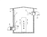
Fig. 2 is a structural representation of the present utility model;
Fig. 3 is the structural representation of the utility model air-intake device 2.
Among the figure: 1-air intake passage 2-air-intake device 3-air-out passage 4-goes out the outdoor probe 7-of the indoor probe 6-of wind apparatus 5-air-conditioner controller 8-filter protection net 9-and filters Air Filter 10-air door 11-electric operator 12-fan 13-master controller 14-housing
The specific embodiment
Below in conjunction with embodiment and accompanying drawing, the utility model is described in further detail.
Following embodiment is non-limiting embodiment of the present utility model.
Embodiment 1:
As shown in Figure 1, 2, the utility model machine room intelligent energy-saving ventilation system comprises air intake passage 1 and the air-out passage 3 be located on the machine room wall, be arranged on air-intake device 2 in the air intake passage 1, be arranged on the outdoor probe 6, air-conditioner controller 7 and the master controller 13 that go out wind apparatus 4, the indoor probe 5 that can detect indoor temperature and humidity, can detect outdoor temperature humidity in the air-out passage 3, and master controller 13 is connected by control line with air-intake device 2, the air-conditioner controller 7 that goes out in wind apparatus 4, indoor probe 5, outdoor probe 6 and the machine room respectively.
In the present embodiment, master controller 13 adopts the RISC single-chip microcomputers as main control unit, and built-in Watchdog function and protecting system is to prevent program fleet.Also has an expansion slot in the master controller 13, as the standby numeral and the expansion interface of simulation.Indoor probe 5 and outdoor probe 6 respectively adopt 2 temperature and humidity sensors, are used to detect the temperature and humidity of machine room indoor and outdoor.
As shown in Figure 2, air intake passage 1 is arranged on machine room by on the wall of the back, its ventilating opening distance≤1 overhead meter, air-out passage 3 is arranged on the wall on air intake passage 8 opposites, disembark distance≤1 meter on roof, room of its ventilating opening, when the utility model intelligent power saving ventilating system is worked, outdoor cold air is indoor by air-intake device 2 suction in the air intake passage 1, by taking away heat behind the heat-producing device, and discharge indoorly by the wind apparatus 4 that goes out in the air-out passage 3, exchange to guarantee indoor hot-air and outdoor cold air.
Fig. 3 is the structural representation of the utility model air-intake device 2.As shown in Figure 3, air-intake device 2 comprises housing 14, is the air channel in the housing 14, and air door 10, electric operator 11, fan 12 are arranged in the housing 14, and the front end of housing 10 also has filter protection net 8 and filters Air Filter 9.Wherein the effect of filter protection net 8 is to prevent that bigger fouls such as mosquito from entering; Filter Air Filter 9 and adopt professional air filter screen, to guarantee high efficiency filter.Simultaneously, filter protection net 8 and filtration Air Filter 9 all adopt the housing mounting means, with convenient regular dismounting, cleaning and repeated use, guarantee the clean level of base station room air.Electric operator 11 is motions that control air door 10 opens and closes, and when system moves, by electric operator 11 air door 10 is opened, and opens fan 12 at last with the air inside and outside the switch room; When ventilating system is closed, at first close fan 12, by electric operator 11 air door 10 is closed then, make the air insulated of indoor and outdoor.
The structure that goes out wind apparatus 4 is similar to air-intake device 2, does not need dustproof filter during owing to air-out, so at the front end of housing 14 filter protection net 8 is only arranged, filters Air Filter 9 and do not establish.
In ventilating system when operation,, master controller 13 can pass through the collecting temperature moisture signal, and handles the back through single-chip microcomputer and show, when temperature or humidity are finished the output of various controls, warning and signal when setting value.Specifically, just master controller 13 is by gathering indoor probe 5, outdoor probe 6 detected indoor and outdoor temperature humidity values, and, operate in the environment provided state to guarantee machine room according to the keying that the difference of indoor and outdoor temperature humidity is controlled air-intake device 2, gone out wind apparatus 4 and air-conditioner controller 7.
The operation principle of the utility model ventilating system is as follows:
When the environment temperature that detects machine room when the temperature sensor in the indoor probe 5 is higher than the set temperature value of opening fan, outdoor temperature is lower than indoor temperature (this capable setting parameter) on certain difference simultaneously, and guarantee that outdoor temperature is lower than the unlatching desired temperature of fan (this capable setting parameter), and indoor humidity or outside humidity are in setting humidity range the time, opening ventilating system lowers the temperature: at first master controller 13 control electric operators 11 are opened air door 10, master controller 13 starts fan 12 operations then, make the machine room inner air and outer air force exchange, regulate the temperature in the machine room.When indoor temperature is reduced to the set temperature value of closing fan when following, ventilating system is closed: at first master controller 13 cuts out fan 12 operations, closes air door 10 by electric operator 11 then, prevents that dust from entering.When indoor, outdoor temperature all when the set temperature value of opening fan is above, method by simple indoor and outdoor ventilation cooling lost efficacy, if this moment, indoor temperature surpassed air-conditioning turn-on temperature setting value, master controller 13 will start air-conditioner controller 7 (master controller 13 is controlled air-conditioner controller 7 by the switching of controlling a relay), utilize air-conditioning that machine room is lowered the temperature.
When alternating current is working properly, the utility model intelligent power saving ventilating system one total following 4 duties:
1, when indoor temperature was lower than the high temperature setting value of system, the utility model ventilating system and air-conditioning all were failure to actuate;
2, when being higher than high temperature, indoor temperature sets value, outdoor temperature is lower than the high temperature setting value, when indoor or outside humidity is lower than humidity set point simultaneously, opening ventilating system lowers the temperature naturally, when indoor temperature is reduced to below the low temperature setting value, when perhaps indoor/outdoor temperature-difference is in 2 ℃, close the fan in the ventilating system;
3, set value when indoor temperature is higher than high temperature, outdoor temperature is lower than the high temperature setting value, and when still indoor and outside humidity all was higher than humidity set point, the air-conditioning temperature-reducing in the opening chamber when indoor temperature is lower than the low temperature setting value, was closed air-conditioning;
4, when indoor temperature and outdoor temperature all are higher than the high temperature setting value, open air-conditioning temperature-reducing.
When alternating current work was undesired, the work of the utility model ventilating system had following 2 duties:
1, set value when indoor temperature is higher than high temperature, outdoor temperature and indoor temperature have 3 ℃ the temperature difference, when indoor or outside humidity is lower than humidity set point simultaneously, opens ventilating system and lower the temperature naturally;
2, except that above-mentioned 1 situation, all close fan in the ventilating system.
Claims (9)
1. machine room intelligent energy-saving ventilation system, it is characterized in that comprising the air intake passage (1) and the air-out passage (3) that are divided on the machine room wall, be arranged on the air-intake device (2) in the air intake passage, be arranged on and go out wind apparatus (3) in the air-out passage, the outdoor probe (6) and the indoor probe (5) that can detect the indoor and outdoor humiture respectively, air-conditioner controller (7) and master controller (13), master controller respectively with outdoor probe, indoor probe, air-intake device, go out wind apparatus, air-conditioner controller is electrically connected, and, control air-intake device according to the difference of indoor and outdoor temperature humidity by gathering outdoor probe and the detected indoor and outdoor temperature humidity value of indoor probe, go out the keying of wind apparatus and air-conditioner controller.
2. machine room intelligent energy-saving ventilation system according to claim 1, it is characterized in that described air-intake device comprises housing (14), be the air channel in the housing, the air door (10) that can seal described air channel arranged in the housing and outdoor air can be blown into indoor fan (12).
3. machine room intelligent energy-saving ventilation system according to claim 2 is characterized in that the preceding screen pack that is provided with of described housing (14).
4. machine room intelligent energy-saving ventilation system according to claim 3 is characterized in that described screen pack comprises the filtration Air Filter (9) of outer field filter protection net (8) and internal layer.
5. machine room intelligent energy-saving ventilation system according to claim 1, it is characterized in that describedly going out wind apparatus and comprising housing (14), be the air channel in the housing, the air door (10) that can seal described air channel arranged in the housing and room air can be blown to outdoor fan (12).
6. machine room intelligent energy-saving ventilation system according to claim 3 is characterized in that before the described housing filter protection net (8) being arranged.
7. machine room intelligent energy-saving ventilation system according to claim 1 is characterized in that described air intake passage (2) is installed on machine room by on the back wall, and described air-out passage (3) is installed on the wall on air intake passage opposite.
8. machine room intelligent energy-saving ventilation system according to claim 7 is characterized in that disembark distance≤1 meter on roof, room of described air intake passage (2) distance≤1 overhead meter, air-out passage (3).
9. according to the described machine room intelligent energy-saving ventilation system of one of claim 1-8, it is characterized in that master controller (13) adopts the RISC single-chip microcomputer as main control unit.
Priority Applications (1)
| Application Number | Priority Date | Filing Date | Title |
|---|---|---|---|
| CNU2007201958259U CN201121959Y (en) | 2007-10-29 | 2007-10-29 | Intelligent energy-saving ventilating system of machine room |
Applications Claiming Priority (1)
| Application Number | Priority Date | Filing Date | Title |
|---|---|---|---|
| CNU2007201958259U CN201121959Y (en) | 2007-10-29 | 2007-10-29 | Intelligent energy-saving ventilating system of machine room |
Publications (1)
| Publication Number | Publication Date |
|---|---|
| CN201121959Y true CN201121959Y (en) | 2008-09-24 |
Family
ID=40009188
Family Applications (1)
| Application Number | Title | Priority Date | Filing Date |
|---|---|---|---|
| CNU2007201958259U Expired - Fee Related CN201121959Y (en) | 2007-10-29 | 2007-10-29 | Intelligent energy-saving ventilating system of machine room |
Country Status (1)
| Country | Link |
|---|---|
| CN (1) | CN201121959Y (en) |
Cited By (22)
| Publication number | Priority date | Publication date | Assignee | Title |
|---|---|---|---|---|
| CN101997276A (en) * | 2010-10-20 | 2011-03-30 | 承方 | High voltage capacitor chamber with adjacent structure |
| CN102155776A (en) * | 2011-04-08 | 2011-08-17 | 无锡高远电力科技有限公司 | Ventilating and temperature-reducing transformer substation building structure utilizing temperature difference of temperature field |
| CN102466297A (en) * | 2010-11-16 | 2012-05-23 | 秦金红 | Method and device for controlling real-time dynamic temperatures of machine room and base station |
| CN101865506B (en) * | 2009-04-14 | 2012-07-11 | 曾国辉 | Monitoring and control method of air conditioner energy saving system |
| CN102662422A (en) * | 2012-05-10 | 2012-09-12 | 华为技术有限公司 | Cabinet control method and communication device |
| CN103175281A (en) * | 2011-12-22 | 2013-06-26 | 上海邮电设计咨询研究院有限公司 | Energy-saving communication machine room capable of directly introducing fresh air |
| CN103261804A (en) * | 2011-03-14 | 2013-08-21 | 富士电机株式会社 | Outside air utilization air-conditioning system and air-conditioner thereof |
| CN103640458A (en) * | 2013-11-19 | 2014-03-19 | 徐工集团工程机械股份有限公司科技分公司 | Air filtering device for loader cab |
| CN104048382A (en) * | 2014-06-26 | 2014-09-17 | 国家电网公司 | Low-noise energy-saving ventilation and heat dissipation method for indoor electrical device |
| CN104602483A (en) * | 2013-10-30 | 2015-05-06 | 艾默生网络能源有限公司 | Refrigerating control method, device and system for cabinet |
| CN104765395A (en) * | 2015-03-27 | 2015-07-08 | 山东齐林电力设备有限公司 | Operating environment control system and method for KYN series central switch cabinet |
| CN105222269A (en) * | 2015-09-16 | 2016-01-06 | 唐棣 | A kind of substation control system and control method |
| CN105241030A (en) * | 2015-11-05 | 2016-01-13 | 国网浙江建德市供电公司 | Computer room environment control method and intelligent control system of computer room |
| CN106786068A (en) * | 2017-03-07 | 2017-05-31 | 陆映红 | A kind of power scheduling power distribution cabinet |
| CN107036229A (en) * | 2016-11-29 | 2017-08-11 | 奥克斯空调股份有限公司 | Air-conditioning and its control method |
| CN107702254A (en) * | 2017-11-02 | 2018-02-16 | 郑州云海信息技术有限公司 | A kind of single data center of band brattice |
| CN108167997A (en) * | 2017-12-27 | 2018-06-15 | 合肥睿致新科技有限公司 | A kind of indoor ventilator unit based on Internet of Things control |
| CN110119172A (en) * | 2019-04-19 | 2019-08-13 | 广州供电局有限公司 | Power distribution room environment parameter control system |
| CN111578471A (en) * | 2020-05-20 | 2020-08-25 | 安徽远洋电力工程有限公司 | Unattended electric power comprehensive automatic monitoring system, method and storage medium |
| CN112242656A (en) * | 2019-07-17 | 2021-01-19 | 江苏瀚晨电气科技有限公司 | Ring main unit capable of automatically controlling refrigerating air |
| CN112556061A (en) * | 2021-01-07 | 2021-03-26 | 深圳博强建设开发有限公司 | Ventilation system and method |
| CN114578874A (en) * | 2020-11-28 | 2022-06-03 | 中国石油天然气集团有限公司 | Valve chamber equipment room |
-
2007
- 2007-10-29 CN CNU2007201958259U patent/CN201121959Y/en not_active Expired - Fee Related
Cited By (32)
| Publication number | Priority date | Publication date | Assignee | Title |
|---|---|---|---|---|
| CN101865506B (en) * | 2009-04-14 | 2012-07-11 | 曾国辉 | Monitoring and control method of air conditioner energy saving system |
| CN101997276B (en) * | 2010-10-20 | 2012-05-23 | 承方 | High voltage capacitor chamber with adjacent structure |
| CN101997276A (en) * | 2010-10-20 | 2011-03-30 | 承方 | High voltage capacitor chamber with adjacent structure |
| CN102466297A (en) * | 2010-11-16 | 2012-05-23 | 秦金红 | Method and device for controlling real-time dynamic temperatures of machine room and base station |
| CN103261804A (en) * | 2011-03-14 | 2013-08-21 | 富士电机株式会社 | Outside air utilization air-conditioning system and air-conditioner thereof |
| CN102155776A (en) * | 2011-04-08 | 2011-08-17 | 无锡高远电力科技有限公司 | Ventilating and temperature-reducing transformer substation building structure utilizing temperature difference of temperature field |
| CN103175281A (en) * | 2011-12-22 | 2013-06-26 | 上海邮电设计咨询研究院有限公司 | Energy-saving communication machine room capable of directly introducing fresh air |
| CN102662422B (en) * | 2012-05-10 | 2014-11-05 | 华为技术有限公司 | Cabinet control method and communication device |
| CN102662422A (en) * | 2012-05-10 | 2012-09-12 | 华为技术有限公司 | Cabinet control method and communication device |
| CN104602483A (en) * | 2013-10-30 | 2015-05-06 | 艾默生网络能源有限公司 | Refrigerating control method, device and system for cabinet |
| CN103640458B (en) * | 2013-11-19 | 2016-05-25 | 徐工集团工程机械股份有限公司科技分公司 | Loader cab air filter |
| CN103640458A (en) * | 2013-11-19 | 2014-03-19 | 徐工集团工程机械股份有限公司科技分公司 | Air filtering device for loader cab |
| CN104048382B (en) * | 2014-06-26 | 2016-04-06 | 国家电网公司 | Indoor electric equipment low-noise energy-saving ventilation and heat method |
| CN104048382A (en) * | 2014-06-26 | 2014-09-17 | 国家电网公司 | Low-noise energy-saving ventilation and heat dissipation method for indoor electrical device |
| CN104765395A (en) * | 2015-03-27 | 2015-07-08 | 山东齐林电力设备有限公司 | Operating environment control system and method for KYN series central switch cabinet |
| CN104765395B (en) * | 2015-03-27 | 2017-04-12 | 山东齐林电力设备股份有限公司 | Operating environment control system and method for KYN series central switch cabinet |
| CN105222269A (en) * | 2015-09-16 | 2016-01-06 | 唐棣 | A kind of substation control system and control method |
| CN105222269B (en) * | 2015-09-16 | 2017-12-22 | 襄阳浩宇科技咨询有限公司 | A kind of substation control system and control method |
| CN105241030B (en) * | 2015-11-05 | 2019-01-08 | 国网浙江建德市供电公司 | A kind of building environment control method and machine room intelligent control system |
| CN105241030A (en) * | 2015-11-05 | 2016-01-13 | 国网浙江建德市供电公司 | Computer room environment control method and intelligent control system of computer room |
| CN107036229A (en) * | 2016-11-29 | 2017-08-11 | 奥克斯空调股份有限公司 | Air-conditioning and its control method |
| CN107036229B (en) * | 2016-11-29 | 2022-11-22 | 奥克斯空调股份有限公司 | Air conditioner and control method thereof |
| CN106786068A (en) * | 2017-03-07 | 2017-05-31 | 陆映红 | A kind of power scheduling power distribution cabinet |
| CN107702254A (en) * | 2017-11-02 | 2018-02-16 | 郑州云海信息技术有限公司 | A kind of single data center of band brattice |
| CN108167997A (en) * | 2017-12-27 | 2018-06-15 | 合肥睿致新科技有限公司 | A kind of indoor ventilator unit based on Internet of Things control |
| CN110119172A (en) * | 2019-04-19 | 2019-08-13 | 广州供电局有限公司 | Power distribution room environment parameter control system |
| CN112242656A (en) * | 2019-07-17 | 2021-01-19 | 江苏瀚晨电气科技有限公司 | Ring main unit capable of automatically controlling refrigerating air |
| CN112242656B (en) * | 2019-07-17 | 2022-05-27 | 江苏瀚晨电气科技有限公司 | Ring main unit capable of automatically controlling refrigeration air |
| CN111578471A (en) * | 2020-05-20 | 2020-08-25 | 安徽远洋电力工程有限公司 | Unattended electric power comprehensive automatic monitoring system, method and storage medium |
| CN114578874A (en) * | 2020-11-28 | 2022-06-03 | 中国石油天然气集团有限公司 | Valve chamber equipment room |
| CN114578874B (en) * | 2020-11-28 | 2023-10-31 | 中国石油天然气集团有限公司 | Valve chamber equipment room |
| CN112556061A (en) * | 2021-01-07 | 2021-03-26 | 深圳博强建设开发有限公司 | Ventilation system and method |
Similar Documents
| Publication | Publication Date | Title |
|---|---|---|
| CN201121959Y (en) | Intelligent energy-saving ventilating system of machine room | |
| CN102353115B (en) | Communication base station energy saving device, system for controlling same, and control method thereof | |
| CN100480593C (en) | Air-conditioning energy-saving monitoring system of base station | |
| CN201837014U (en) | Base station intelligent ventilating system | |
| CN210772639U (en) | Energy-saving centralized control management system for communication machine room | |
| CN201488133U (en) | Full-process intelligent control ventilation device | |
| CN201892867U (en) | Intelligent air exchange control system for communication base station | |
| CN105157182B (en) | Base station heat source intelligent management energy conserving system | |
| CN101893301A (en) | Heat removal and temperature control energy-saving system for mobile communication base station | |
| CN202886918U (en) | Enclosed space environment monitoring and controlling device | |
| CN201652703U (en) | Intelligent ventilation temperature-control energy-saving system | |
| CN105674513B (en) | A kind of base station machine room energy saving ventilation system and regulation method | |
| CN101749824A (en) | Natural cooling intelligent fan set and using method thereof | |
| CN202885154U (en) | Intelligent ventilation energy-saving device | |
| CN201764611U (en) | Heat-extraction temperature-control energy-saving system of mobile communication base station | |
| CN107859464A (en) | Intelligent multifunctional temperature air controlling of quality window | |
| CN203533710U (en) | All-purpose intelligent control air conditioning system | |
| CN105276693A (en) | Air purifier system with fresh air function | |
| CN103712317A (en) | Novel machine room ventilation and energy conservation system and airflow direction changing method thereof | |
| CN105157187B (en) | A kind of base station thermal source intelligent management energy conserving system | |
| CN203385137U (en) | Energy-saving ventilation system for air supply air-conditioner of communication machine room | |
| CN2922397Y (en) | Machinery-room intelligent ventilation system | |
| CN108759012B (en) | Control system and control method of fresh air conditioner | |
| CN201014673Y (en) | Base station air conditioner energy-saving monitoring apparatus | |
| CN203518133U (en) | Base station energy-saving monitoring system |
Legal Events
| Date | Code | Title | Description |
|---|---|---|---|
| C14 | Grant of patent or utility model | ||
| GR01 | Patent grant | ||
| CF01 | Termination of patent right due to non-payment of annual fee | ||
| CF01 | Termination of patent right due to non-payment of annual fee |
Granted publication date: 20080924 Termination date: 20161029 |