CN201112811Y - Array type module connector - Google Patents
Array type module connector Download PDFInfo
- Publication number
- CN201112811Y CN201112811Y CNU2007201255412U CN200720125541U CN201112811Y CN 201112811 Y CN201112811 Y CN 201112811Y CN U2007201255412 U CNU2007201255412 U CN U2007201255412U CN 200720125541 U CN200720125541 U CN 200720125541U CN 201112811 Y CN201112811 Y CN 201112811Y
- Authority
- CN
- China
- Prior art keywords
- connector
- metal
- socket
- shell
- array
- Prior art date
- Legal status (The legal status is an assumption and is not a legal conclusion. Google has not performed a legal analysis and makes no representation as to the accuracy of the status listed.)
- Expired - Fee Related
Links
Images

Abstract
The utility model relates to an array-type module connector, which comprises a case with a plurality of array-type vessels, a plurality of connectors arranged on the vessels, an extended connector and a set of metal enclosing cover, wherein, the case is provided with an extended section having a plurality of wire holes; a gap part is arranged on one side of the case; all connectors comprise a socket, a metal case and wires passing out of the wire holes, and a conductor is arranged between the metal case of all connectors; the extended connector is arranged in the gap part and comprises a case, a socket, a metal spring and wires; the metal enclosing cover is arranged on the case and in contact with the metal case, the conductor and the metal spring. Therefore, the array-type module connector is provided with the effects of easy assembly and disassembly, can increase the grounding area of the module connector and improve the impedance value, thus achieving a better effect of preventing electromagnetic interference (EMI).
Description
Technical field
The utility model relates to a kind of array modular type connector, refer to especially a kind of have be easy to the effect assembling, dismantle, and can increase the contact area of this modular type connector, and promote resistance value, and reach the effect of preferable Electromagnetic Interference control (EMI).
Background technology
Its circumscribed connector of general existing main frame is fixedly arranged on an ora terminalis of motherboard usually, and the socket correspondence that makes each connector is exposed an end face of main frame, use the grafting expansion that each connector that allows the user utilize the main frame end face carries out external equipment, reach the convenience that external equipment uses.
Though above-mentioned existing main frame can reach the convenience that external equipment uses by the circumscribed connector on its end face; But because each connector is fixedly arranged on an ora terminalis of motherboard, therefore, each connector promptly can't be dismantled after setting is finished, in case when diminishing the situation generation of changing, user and can't changeing voluntarily can only send by the specialized maintenance merchant and change, and causes the not shortcoming of easy-maintaining and replacing; And because each connector is only corresponding with casing with its outside iron-clad, therefore, not only contact area is less, and can't promote its resistance value, and then makes the screening effect variation of each connector, causes the opering characteristic of electric apparatus of each connector to be affected.So, the circumscribed connector on the existing general computer and can't be realistic required during use.
Summary of the invention
Main purpose of the present utility model is to overcome the deficiencies in the prior art and defective, a kind of array modular type connector is proposed, can make the utlity model has and be easy to the effect assembling, dismantle, and utilize metal shell, conductor, metal clips and the metal cover be in contact with one another, increase the contact area of this modular type connector, and the lifting resistance value, and reach the effect that preferable Electromagnetic Interference is prevented and treated (EMI).
For reaching above-mentioned purpose, the utility model provides a kind of array modular type connector, it comprises: a housing, be provided with a plurality of be array arrangement and the opening-like storage tanks of an end, the other end of this housing has an extension, have the wire hole that is communicated with storage tank respectively on this extension, and be provided with a notch part in a side of this housing; A plurality of connectors are located at respectively in above-mentioned each storage tank, and each connector includes metal shell that a socket, is coated on the socket outside, and gang socket and the lead that passed by wire hole at least, and has a conductor between the metal shell of each connector respectively; One expansion connector, be arranged in the notch part of above-mentioned housing, and this expansion connector has a shell, at least and is located in the shell and the socket, that is coated with metal shell is located at metal clips between shell and socket, and gang socket and the lead that passed by shell; And a metal cover, be sheathed on the above-mentioned housing and contact, and have the perforation of each connector of a plurality of confessions and the set socket correspondence of expansion connector on the one side of this metal cover with the metal clips of metal shell, conductor and the expansion connector of each connector.
The utlity model has following useful technique effect: array modular type connector provided by the utility model, can make the utlity model has and be easy to the effect assembling, dismantle, and utilize metal shell, conductor, metal clips and the metal cover be in contact with one another, increase the contact area of this modular type connector, and the lifting resistance value, and reach the effect that preferable Electromagnetic Interference is prevented and treated (EMI).
Description of drawings
Fig. 1 is a three-dimensional appearance schematic diagram of the present utility model;
Fig. 2 is the three-dimensional appearance schematic diagram of another angle of the utility model;
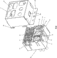
Fig. 3 is a perspective exploded view of the present utility model;
Fig. 4 is the decomposing schematic representation of the utility model housing and metal cover;
Fig. 5 is an assembled state schematic diagram of the present utility model.
Symbol description among the figure
1 housing
11 storage tanks
111 trips
12 extensions
121 wire holes
13 notch parts
131 guide rails
14 depressed parts
2 connectors
21 sockets
22 metal shells
23 leads
24 conductors
3 expansion connectors
31 shells
311 chutes
32 metal shells
33 sockets
34 metal clipss
35 leads
4 metal covers
41 perforation
42 top triggers
43 wing plates
431 fixing holes
44 collude body
5 panels
51 perforation
Embodiment
See also shown in Fig. 1,2,3 and 4, be respectively the decomposing schematic representation of the three-dimensional appearance schematic diagram of three-dimensional appearance schematic diagram of the present utility model, another angle of the utility model, perspective exploded view of the present utility model and the utility model housing and metal cover.As shown in the figure: the utility model provides a kind of array modular type connector, and it is made of a housing 1, a plurality of connector 2, an expansion connector 3 and a metal cover 4; Can make the utlity model has to be easy to the effect assembling, dismantle, and can increase the contact area of this modular type connector, and promote resistance value, and reach the effect of preferable Electromagnetic Interference control (EMI).
The above-mentioned housing of carrying 1 is provided with a plurality of be array arrangement and the opening-like storage tanks 11 of an end, each storage tank 11 at least one side has a trip 111 respectively, and the other end of this housing 1 has an extension 12, has the wire hole 121 that is communicated with storage tank 11 respectively on this extension 12, and be provided with a notch part 13 in a side of this housing 1, be respectively equipped with a guide rail 131 at least two sidewalls of this notch part 13, on the biend at least of this housing 1, be respectively equipped with a depressed part 14 in addition.
Each connector 2 is located at respectively in above-mentioned each storage tank 11, and fixed by trip 111, each connector 2 includes metal shell 22 that a socket 21, is coated on socket 21 outsides, and gang socket 21 and the lead 23 that passed by wire hole 121 at least, 22 of the metal shells of each connector 2 have a conductor 24 respectively, and each conductor 24 can be a wire netting.
This expansion connector 3 is arranged in the notch part 13 of above-mentioned housing 1, this expansion connector 3 has a shell 31, at least and is located in the shell 31 and the socket 33, that is coated with metal shell 32 is located at metal clips 34, and the gang socket 33 and the lead 35 that passed by shell 31 of 33 of shell 31 and sockets, be respectively equipped with on these shell 31 at least two sidewalls one with the chute 311 of notch part 13 set guide rails 131 interlockings.
This metal cover 4 is sheathed on the above-mentioned housing 1, and contact with the metal clips 34 of metal shell 22, conductor 24 and the expansion connector 3 of each connector 2, the perforation 41 that has each connector 2 of a plurality of confessions and expansion connector 3 set socket 21,33 correspondences on the one side of this metal cover 4, and on the biend at least of this metal cover 4, be respectively equipped with one with the top trigger 42 of set depressed part 14 clampings of housing 1 biend, and the lateral margin of this metal cover 4 is provided with a wing plate 43 with fixing hole 431, and a plurality of bodies 44 that collude respectively.Constitute a brand-new array modular type connector by above-mentioned structure.
See also shown in Figure 5, assembled state schematic diagram of the present utility model.As shown in the figure: when the utility model in when assembling, the utility model can be arranged at the front end or the rear end of a computer housing panel 5, modern is example with the front end that is arranged at computer housing panel 5, when assembling, with the perforation 51 of the utility model corresponding to computer housing panel 5, and make the fixing hole 431 of these metal cover 4 upper flanges 43 cooperate the retaining element (not shown) to lock and be fixed on the computer housing panel 5 by fixing hole 431, and collude with panel 5 and close the location to collude body 44, so, the utility model can be assembled on the panel 5 of computer housing front end, and with the lead 23 of each connector 2 and expansion connector 3,35 electrically connect (not shown) with motherboard, can finish assembling of the present utility model; Only need during dismounting this retaining element removal is removed the lead 23,35 that is connected with motherboard on each connector 2 and the expansion connector 3 again; So, can make the utlity model has and be easy to the effect assembling, dismantle.
When the user is plugged in each connector 2 with outside connector (not shown), can be directly by the socket 21 of each connector 2 and expansion connector 3,33 insert, make each socket 21,33 electrically conduct carries out required signal transmission, when each socket 21,33 carry out signal when transmission, then can utilize metal shell 22, conductor 24, metal clips 34 is in contact with one another with metal cover 4 (please cooperate with reference to figure 4), and increase the contact area of each connector 2 and expansion connector 3 and promote resistance value, and when each connector 2 and expansion connector 3 uses, reach the effect that preferable Electromagnetic Interference is prevented and treated (EMI).
In sum, the utility model array modular type connector, can make the utlity model has and be easy to the effect assembling, dismantle, and utilize metal shell, conductor, metal clips and the metal cover be in contact with one another, increase the contact area of this modular type connector, and the lifting resistance value is prevented and treated the effect of (EMI) and reach preferable Electromagnetic Interference, and then is made the utility model can more progressive, more practical, more meet the required of user.
The above only is preferred embodiment of the present utility model, when not limiting the scope that the utility model is implemented with this; So all simple equivalent of doing according to the utility model claims and description change and modify, all should still belong in the scope that the utility model patent contains.
Claims (7)
1. an array modular type connector is characterized in that, comprising:
One housing is provided with a plurality of be array arrangement and the opening-like storage tanks of an end, and the other end of this housing has an extension, has the wire hole that is communicated with storage tank respectively on this extension, and is provided with a notch part in a side of this housing;
A plurality of connectors are located at respectively in above-mentioned each storage tank, and each connector includes metal shell that a socket, is coated on the socket outside, and gang socket and the lead that passed by wire hole at least, and has a conductor between the metal shell of each connector respectively;
One expansion connector, be arranged in the notch part of above-mentioned housing, and this expansion connector has a shell, at least and is located in the shell and the socket, that is coated with metal shell is located at metal clips between shell and socket, and gang socket and the lead that passed by shell; And
One metal cover is sheathed on the above-mentioned housing and contacts with the metal clips of metal shell, conductor and the expansion connector of each connector, and has the perforation of each connector of a plurality of confessions and the set socket correspondence of expansion connector on the one side of this metal cover.
2. array modular type connector as claimed in claim 1 is characterized in that, is respectively equipped with a depressed part on the biend at least of this housing.
3. array modular type connector as claimed in claim 1 is characterized in that at least one side of each storage tank has a trip respectively.
4. array modular type connector as claimed in claim 1 is characterized in that, is respectively equipped with a guide rail at least two sidewalls of this notch part.
5. array modular type connector as claimed in claim 1 is characterized in that each conductor can be a wire netting.
6. array modular type connector as claimed in claim 1 is characterized in that the shell of this expansion connector is provided with a chute respectively at least two sidewalls.
7. array modular type connector as claimed in claim 1 is characterized in that, is respectively equipped with a top trigger on the biend at least of this metal cover, and the lateral margin of this metal cover is provided with a wing plate with fixing hole, and a plurality of bodies that collude respectively.
Priority Applications (1)
| Application Number | Priority Date | Filing Date | Title |
|---|---|---|---|
| CNU2007201255412U CN201112811Y (en) | 2007-09-06 | 2007-09-06 | Array type module connector |
Applications Claiming Priority (1)
| Application Number | Priority Date | Filing Date | Title |
|---|---|---|---|
| CNU2007201255412U CN201112811Y (en) | 2007-09-06 | 2007-09-06 | Array type module connector |
Publications (1)
| Publication Number | Publication Date |
|---|---|
| CN201112811Y true CN201112811Y (en) | 2008-09-10 |
Family
ID=39964559
Family Applications (1)
| Application Number | Title | Priority Date | Filing Date |
|---|---|---|---|
| CNU2007201255412U Expired - Fee Related CN201112811Y (en) | 2007-09-06 | 2007-09-06 | Array type module connector |
Country Status (1)
| Country | Link |
|---|---|
| CN (1) | CN201112811Y (en) |
Cited By (6)
| Publication number | Priority date | Publication date | Assignee | Title |
|---|---|---|---|---|
| CN101752690B (en) * | 2008-11-28 | 2012-01-04 | 鸿富锦精密工业(深圳)有限公司 | Connector device |
| WO2012159961A1 (en) * | 2011-05-24 | 2012-11-29 | Weidmüller Interface GmbH & Co. KG | Structural element for a plug-in unit for connecting electric components, and plug-in unit for a vehicle, in particular a rail vehicle |
| CN103376881A (en) * | 2012-04-23 | 2013-10-30 | 鸿富锦精密工业(深圳)有限公司 | Interface device and server with same |
| CN104798264A (en) * | 2012-11-20 | 2015-07-22 | 矢崎总业株式会社 | Shielded connector |
| CN103441392B (en) * | 2013-09-09 | 2015-10-14 | 上海航天科工电器研究院有限公司 | Mixing type connector plug |
| CN105098518A (en) * | 2014-05-14 | 2015-11-25 | Smk株式会社 | Shield connector |
-
2007
- 2007-09-06 CN CNU2007201255412U patent/CN201112811Y/en not_active Expired - Fee Related
Cited By (9)
| Publication number | Priority date | Publication date | Assignee | Title |
|---|---|---|---|---|
| CN101752690B (en) * | 2008-11-28 | 2012-01-04 | 鸿富锦精密工业(深圳)有限公司 | Connector device |
| WO2012159961A1 (en) * | 2011-05-24 | 2012-11-29 | Weidmüller Interface GmbH & Co. KG | Structural element for a plug-in unit for connecting electric components, and plug-in unit for a vehicle, in particular a rail vehicle |
| CN103376881A (en) * | 2012-04-23 | 2013-10-30 | 鸿富锦精密工业(深圳)有限公司 | Interface device and server with same |
| CN104798264A (en) * | 2012-11-20 | 2015-07-22 | 矢崎总业株式会社 | Shielded connector |
| EP2924813A4 (en) * | 2012-11-20 | 2016-06-22 | Yazaki Corp | Shielded connector |
| CN104798264B (en) * | 2012-11-20 | 2017-04-12 | 矢崎总业株式会社 | Shielded connector |
| CN103441392B (en) * | 2013-09-09 | 2015-10-14 | 上海航天科工电器研究院有限公司 | Mixing type connector plug |
| CN105098518A (en) * | 2014-05-14 | 2015-11-25 | Smk株式会社 | Shield connector |
| CN105098518B (en) * | 2014-05-14 | 2018-09-14 | Smk株式会社 | Shielded connector |
Similar Documents
| Publication | Publication Date | Title |
|---|---|---|
| CN201887274U (en) | Cable connector component | |
| CN201708364U (en) | Cable connector assembly | |
| CN201112811Y (en) | Array type module connector | |
| CN102437482B (en) | Electrical connector | |
| CN201252173Y (en) | Cable connector component | |
| US8221160B2 (en) | Connector assembly having grounding means | |
| US20110306244A1 (en) | Cable connector assembly having an adapter plate for grounding | |
| CN103280670A (en) | Socket electric connector for inhibiting signal interference | |
| CN100382392C (en) | Electrical card connector | |
| US9385450B2 (en) | Cable connector assembly | |
| CN204179274U (en) | Electric connector combination | |
| CN200972963Y (en) | Electric connector | |
| CN201440532U (en) | Cable connector assembly | |
| US20190190213A1 (en) | Cable connector assembly | |
| CN103746201B (en) | High-frequency data plug and electrical harnesses cable | |
| CN202564700U (en) | Electrical connector and thin electronic device using the same | |
| CN101604800B (en) | Connector structure | |
| CN201112847Y (en) | Module type connector structure | |
| CN201018116Y (en) | Structure of electric connector | |
| CN201498781U (en) | Cable connector component | |
| CN202930584U (en) | Universal serial bus connector | |
| CN203787649U (en) | Network connector suitable for SMT manufacturing process | |
| CN201113028Y (en) | Electric connector | |
| CN201774167U (en) | Connecting terminal for circuit breaker | |
| CN201029191Y (en) | Electrical connector |
Legal Events
| Date | Code | Title | Description |
|---|---|---|---|
| C14 | Grant of patent or utility model | ||
| GR01 | Patent grant | ||
| EE01 | Entry into force of recordation of patent licensing contract |
Assignee: Dongguan morning electric products Co., Ltd. Assignor: Golden Bridge Electech Inc. Contract record no.: 2010990000081 Denomination of utility model: Array type module connector Granted publication date: 20080910 License type: Exclusive License Record date: 20100220 |
|
| C17 | Cessation of patent right | ||
| CF01 | Termination of patent right due to non-payment of annual fee |
Granted publication date: 20080910 Termination date: 20110906 |