CN201109083Y - Improved fast clamp for working bench - Google Patents
Improved fast clamp for working bench Download PDFInfo
- Publication number
- CN201109083Y CN201109083Y CNU2007201701610U CN200720170161U CN201109083Y CN 201109083 Y CN201109083 Y CN 201109083Y CN U2007201701610 U CNU2007201701610 U CN U2007201701610U CN 200720170161 U CN200720170161 U CN 200720170161U CN 201109083 Y CN201109083 Y CN 201109083Y
- Authority
- CN
- China
- Prior art keywords
- lifting body
- aperture
- inserted link
- screw rod
- clamping bar
- Prior art date
- Legal status (The legal status is an assumption and is not a legal conclusion. Google has not performed a legal analysis and makes no representation as to the accuracy of the status listed.)
- Expired - Fee Related
Links
Images


Abstract
The utility model relates to an improved rapid clamp used for a working platform face, and the improved rapid clamp is of a rapid clamp improved structure that can be used for positioning and clamping in the woodworking or other purposes on the working platform face. The structure of the rapid clamp comprises a lifting body, a clamping bar, an inserted link, etc. The rapid clamp is characterized in that an elastic presser bit is arranged between the inserted link and the front end of the lifting body and can be used for fixing or releasing the lifting body to adjust the upper and lower displacement motion of the lifting body; in addition, a whirling grip is arranged above the clamping bar, can quickly fix a workpiece clamp by using the lever principle after the contact height between a base body under the clamping bar and a workpiece is adjusted; a major diameter of thread is made at the bottom of the inserted link, two sleeves provided with an inner screwed hole diameter and cut by a ramp slope way are screwed on the major diameter of thread, when the two sleeves spirally move up and down, the outer diameter of the two sleeves is increased or reduced, so as to position the pore diameter on the working platform to be convenient for the processing operation of the workpiece.
Description
Technical field
The utility model relates to a kind of clamped tool, particularly a kind of can be at the quick folder that presss from both sides the improvement of using the location on the work top on for carpenter or other purposes.
Background technology
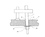
Processed the anchor clamps of use owing to generally be inserted on the work top holding workpiece, the outward appearance kenel has a variety of, really be too numerous to enumerate, but comprehensively its structure all is the make of taking as shown in Figure 1 down, but reaching packing is positioned in the aperture on the work top, as shown in fig. 1, on anchor clamps, be provided with an inserted link 1, directly inserted link 1 is inserted 3 places, default aperture that run through on the work top 2 in skewed mode, make the limit face of inserted link 1 can contact aperture on the work top 22 limit ends 31 about in the of 3,32 places, and then cooperate with nut 33, pad 34 members such as grade, the bottom face that is threaded to work top 2 from the bottom of inserted link 1 is fixed, this packing positioning and fixing mode is to have following disappearance place in the use:
First, its in the use because inserted link 1 limit face contact in the aperture 3 on the wooden work top 2 be about the point of 2 limit ends 31,32 meet the place, so after with nut 33 packings, be easy to as those shown on Fig. 2, these limit end 31 places are dented into or break, so, will have space 35 to produce, and make inserted link 1 heavy curtain in the middle of the processing operation moving, influence workpiece 8 crudies.
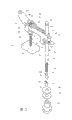
Second, in the structure design of these anchor clamps, be in must be with inserted link 1, insertion runs through outside the default aperture 3 on the work top 2, the mode that fixes with nut 33 packings again, so the work top 2 on it uses just must be limited at the work top 2 that extends through outer aperture 3, bottom fully and can use, there is the work top 2 that does not extend through outer aperture 3, bottom fully just can't use if run into, so occur another anchor clamps structure as shown in Figure 3 recently on the market, though this anchor clamps are provided with a sleeve that can expand outwardly 84 in its bottom, in the time of in the default aperture on inserting work top, can solve above-listed described disappearance place, but the disappearance place that it still has other in the use is described as follows now:
The first, it is textural too numerous and diverse, wants car system screw rod 80 on external diameter, and thread cutting 81 and inner bolt hole 82 again in the internal diameter, cost is very high in the manufacturing.
The second, when using in its default aperture on inserting work top, be to lean on fully to rotate knob 83 with hand, sleeve 84 is expanded outwardly, so very effort inconvenience.
The 3rd, it adjusts slide about in the of 85 the time in the use, be as shown in Figure 4, slide 85 1 ends must be lifted inclination, make two bodies of rod 86,87 in the slide 85 screw rod 80 of conflicting, make its location, heavy curtain was moving or when running into slide 85 because of carelessness when this occupation mode was easy to because of work, it is moving to make slide 85 produce heavy curtain, can't reach fastening function fully.
The 4th, when it wants the clamping workpiece in the use, must make holder 89 downward gradually by rotating knob 88 with hand, very consuming time slow in the operation.
The 5th, the bottom of its holder 89 is the design of smooth linearity, when running into profile and be the workpiece of circular arc, just is not easy clamping.
In view of this, so developing the utility model again, the talent of the present invention offers the convenient use of consumer.
Summary of the invention
The purpose of this utility model is to propose a kind of quick folder when using that can make work top use, must not be limited to the work top that extends through outer aperture, bottom fully can use, can be time saving and energy saving fix clips on the work top fast, and break or dent in inner limit, the aperture that can avoid desktop fixedly the time, produce clearance, fixing unsteady situation, can also solve profile in addition is the difficult problem of reinforcing of workpiece of circular arc.
To achieve these goals, the utility model proposes following scheme:
The quick folder of the improvement that a kind of work top is used is characterized in that: its textural comprising:
But its front end neck of lifting body 4-is provided with the aperture 41 of a up/down perforation, on the front outer face in this aperture 41, has an inner diameter hole seat 42, nearly edge position, 41 lower ends, aperture in its front end neck, has a socket 44, and at the position, rear end of lifting body 4, have an a pair of lug 45 and a pedestal 46, but the central part on lifting body 4 its positions, pedestal rear end offers the screw footpath 47 of a up/down perforation, can screw in combination for the screw rod on the clamping bar 5 51;
Its nearly lower portion of handgrip 93-is provided with a pair of as the end 94 of cam edge face shape and be provided with a cross bar axle 95 on this end 94.
Inserted link 6-is provided with a recessed annular groove 63 at its position, upper end near shaft, snap in it for a clasp 64, at the bottom part of inserted link 6, be provided with one section screw rod 61 and above screw rod 61 the shaft place, offer a recessed breach 62.
Clamping bar 5-is by a screw rod 51, is constituted with a pedestal 52.
Its tail end position of compressing tablet 9-offers an aperture 91, with and the front part position offer a recessed hole seat 92.
Compression spring 43-is that intert in the internal diameter 41 hole seats at lifting body 4 front end necks at position above it when combination, and lower portion is to be interspersed in the hole seat 92 at position, compressing tablet 9 the place ahead.
Two sleeves 72,73-wherein are positioned at the sleeve 73 of lower position, be provided with an internal thread aperture 71 thereon, and be positioned at the sleeve 72 of top position, and being provided with an internal diameter 722 thereon, both can be screwed on the screw rod 61 of inserted link 6 near bottom part with rotation by snare respectively;
The beneficial effects of the utility model are:
Being clipped in fast in the operation that the work top that adopts the utility model to realize is used is comparatively time saving and energy saving, can utilize lever principle, fast workpiece is supported and stop fixed bit, when making in the default aperture of inserted link on inserting work top, can be very fast fully packing be positioned in the aperture on the work top and make things convenient for its processing operation to use.
Brief description of drawings
Fig. 1,2,3, the 4th is the relative configurations figure of prior art.
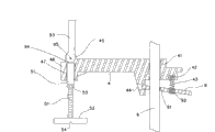
Fig. 5 is D structure exploded view of the present utility model.
Fig. 6 is D structure constitutional diagram of the present utility model.
Fig. 7, the 8th is the plan cross-section relative configurations schematic diagram of utility model.
Fig. 9 is the schematic diagram when rotating inserted link for the utility model with spanner.
Figure 10, the 11st is for the utility model is implemented on the work top enforcement legend when connecting the aperture.
Figure 12 is the schematic diagram of the utility model pedestal when the clamping round piece.
Figure 13 is the enforcement legend when being implemented on holding workpiece on the work top for the utility model.
Figure 14, the 15th, the enforcement legend when being implemented on non-through aperture on the work top for the utility model.
The specific embodiment
See also Fig. 5,6, shown in 7, the utility model is by inserted link 6 of a lifting body 4 collocation, clamping bar 5 and compression spring 43, compressing tablet 9, handgrip 93, two sleeves 72,73 and pad 36, pad 34, nut 33 members such as grade constitute, wherein, but the front end neck of lifting body 4 is provided with the aperture 41 of a up/down perforation, on the front outer face in this aperture 41, moulding has an inner diameter hole seat 42 in addition, again, be positioned at this nearly edge position, 41 lower ends, aperture, then design moulding and have a socket 44, and at the position, rear end of lifting body 4, the design moulding has an a pair of lug 45 and a pedestal 46, wherein, but offer the screw footpath 47 of a up/down perforation at the central part of pedestal 46; Inserted link 6, at its position, upper end near shaft, be provided with a recessed annular groove 63, can snap in it for a clasp 64, be used as adjusting lifting body 4 when inserted link 6 top offsets move on the dead point, preventing that lifting body 4 upwards breaks away from comes, in addition inserted link 6 bottom part, be provided with one section screw rod 61, can make member snare rotations such as two sleeves 72,73 and pad 36, pad 34, nut 33 screw togather collocation thereon and use, again, shaft place above screw rod 61, offer a recessed breach 62, in the time of can supplying rotation inserted link 6, come the clamping rotation with spanner 10; Compressing tablet 9, its tail end position offers an aperture 91, with and the front part position offer a recessed hole seat 92; Handgrip 93, its nearly lower portion are provided with a pair of as the end 94 as the cam edge face shape, and are provided with a cross bar axle 95 on this end 94; Clamping bar 5 is by a screw rod 51, is constituted with a pedestal 52, be combined with a nut 53 on screw rod 51, and the bottom face of pedestal 52 offers groove 54; Two sleeves 72,73, wherein, be positioned at the sleeve 73 of lower position, be provided with an internal thread aperture 71 thereon, and be positioned at the sleeve 72 of top position, be provided with an internal diameter 722 thereon, both can be screwed on the screw rod 61 of inserted link 6 near bottom part with rotation by snare respectively, and collocation pad 36, pad 34, nut 33 members such as grade use, in addition, these two sleeves 72,73 the most special places are it to be designed to be cut in the mode of ramp rate by a sleeve become two, make this two sleeves 72,73 all have a bevelled edge face 721 separately, 731, utilize this two sleeves 72, the bevelled edge face 721 that can contact relatively on 73,731 designs make two sleeves 72,73 when relatively spiral moves up and down, and can make that its outer radial is outer to be increased or inwardly dwindle; Above-mentioned each member when combination is, aperture 41 on lifting body 4 front ends can be interted in it for inserted link 6, but inner diameter hole seat 42 is the contract position, upper end of spring 43 of voltage supply then, be interspersed in it, in addition, after 91 covers of the aperture on the compressing tablet 9 tail end positions are through at inserted link 6, compressing tablet 9 tail end positions just can be interspersed in the socket 44 of lifting body 4 belows, and make the lower end part of compression spring 43, can be inserted in the hole seat 92 at position, compressing tablet 9 the place ahead, again, be positioned at the pedestal 46 on the position, lifting body 4 rear end, 47 in the screw footpath on it can screw in combination for the screw rod on the clamping bar 5 51, and the lug 45 on the position, lifting body 4 rear end, then can intert and make up, and after combination, make the end 94 of handgrip 93 lower portion for the cross bar axle 95 of handgrip 93 belows, can be corresponding on the top end face of clamping bar 5 screw rods 51.
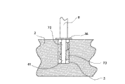
For example shown in Figure 10, when the sleeve 73 that is positioned at the below is driven when screw rod 61 makes progress by inserted link 6 rotations, the sleeve 73 of below just can be along the bevelled edge face 721 of last square socket 72 spiral and promote to go up square socket 72 and move upwards, and then the sleeve outer diameter that both are constituted, and expands outwardly to become greatly, otherwise, as shown in figure 11, when the sleeve 73 that is positioned at the below is rotated when downward, the sleeve 73 of below just downwards spiral move, and then the external diameter that both are constituted, revert to original state and diminish; Work top 2 in running into working environment is when the aperture 3 that extends through fully outside the bottom is arranged, it is exactly as above-mentioned Figure 10 in the use, mode shown in 11, directly inserted link 6 is inserted vertically downward outside default aperture 3 root edges on work top 2, overlap Upper gasket 34 again, and it is fixing with nut 33 rotations, then with spanner 10 rotation inserted links 6 (as shown in Figure 9), the sleeve 73 that is positioned at lower position is driven along screw rod 61 by inserted link 6 rotations, the bevelled edge face 721 of square socket 72 displacement action upwards one by one up, and then make two sleeves 72,73 external diameters, expand outwardly and become big, when two sleeves 72,73 in aperture 3 after the packing, at this moment as long as workpiece is placed the below of pedestal 52, the front end position of pinning compressing tablet 9 with hand upwards then, as Fig. 7, shown in 8, lifting body 4 is moved to adjust the contact height of 8 of pedestal 52 and workpiece at inserted link 6 top offsets, and then with the former hand relieving of pushing down compressing tablet 9, and upwards stir handgrip 93, can utilize lever principle, the end 94 that makes handgrip 93 nearly lower portion is supported the top end face of screw rod 51 to stop and is given fixed bit, easily laborsaving in the operation, behind clamping workpiece 8, do not have fully and unclamp the moving facts generation of heavy curtain, in addition in the time will dismantling workpiece 8, otherwise as long as according to above-mentioned action, handgrip 93 is being stirred downwards, can made workpiece 8 released, again, because the utility model is provided with groove 54 at the bottom face of pedestal 52, so as shown in figure 12, when running into profile and be the workpiece of circular arc, also can be easy to by clamping; In the time of after use, must making inserted link 6 and aperture 3 separate again, just can shown in Fig. 8,11, rotate inserted link 6, make the sleeve 73 that is positioned at lower position can be rotated downward spiral and move, and then sleeve 72,73 external diameters that constituted are diminished with spanner 10; Work top 2 in running into working environment is when the aperture 3 that does not extend through fully outside the bottom is arranged, it then is as Figure 13 in the use, 14, shown in 15, at this moment just need not use pad 34 and nut 33 members, as long as inserted link 6 is directly inserted in the default aperture 3 on the work top 2, make sleeve 73 bottom surfaces that are positioned at the below contact aperture 3 root edges, and then with 6 rotations of spanner 10 rotation inserted links, the sleeve 73 that just can make the below along screw rod 61 up square socket 72 bevelled edge face 721 upwards spiral move, the moving square socket 72 of going up of heap is to top offset one by one, till the pad 51 that contacts on the inserted link 6, so just can make sleeve 72,73 external diameters that constituted, it is big to expand outwardly change, and can contact the aperture 3 limit faces that are fixed on; Above-mentioned fastening locate mode of the present utility model, it is that complete whole limit face with two sleeves 72,73 vertically is close on the 3 limit faces of aperture when fastening, contact between the two is whole straight line face, so do not have and make 3 inner limits, aperture break or dent into the facts, can avoid producing in the aperture clearance, guarantee the steadiness after clamping is located, in addition in order to be increased in the friction on the clamping, the utility model also can be processed into the outer fringe surface of two sleeves 72,73 when implementing has embossing, and itself and friction between 3 inner limits, aperture are become greatly.
Claims (4)
1. the quick folder of the improvement used of a work top is characterized in that: its textural comprising:
Lifting body (4) but-its front end neck is provided with the aperture (41) of a up/down perforation, on the front outer face of this aperture (41), has an inner diameter hole seat (42), nearly edge position, lower end, aperture (41) in its front end neck, has a socket (44), and at the position, rear end of lifting body (4), have an a pair of lug (45) and a pedestal (46), at lifting body (4) but the central part on its position, pedestal rear end offers the screw footpath (47) of a up/down perforation, can supply screw rod (51) on the clamping bar (5) to screw in and make up;
Handgrip (93)-its nearly lower portion is provided with a pair of end as cam edge face shape (94) and is provided with a cross bar axle (95) on this end (94);
Inserted link (6)-at its position, upper end near shaft, be provided with a recessed annular groove (63), snap in it bottom part in inserted link (6) for a clasp (64), be provided with one section screw rod (61) and, offer a recessed breach (62) at the shaft place, top of screw rod (61);
Clamping bar (5)-be by a screw rod (51), constituted with a pedestal (52);
Compressing tablet (9)-its tail end position offers an aperture (91), with and the front part position offer a recessed hole seat (92);
Compression spring (43)-be that intert in the seat of internal diameter (41) hole of lifting body (4) front end neck at position above it when combination, and lower portion is to be interspersed in the hole seat (92) at compressing tablet (9) position, the place ahead;
Two sleeves (72,73)-wherein be positioned at sleeve (73) of lower position, be provided with an internal thread aperture (71) thereon, and be positioned at the sleeve (72) of top position, be provided with an internal diameter (722) thereon, both respectively can snare and rotation be screwed on the screw rod (61) of inserted link (6) near bottom part;
Aperture (41) on lifting body (4) front end can supply inserted link (6) to intert in it, the position, upper end of inner diameter hole seat (42) spring (43) but voltage supply is contracted is interspersed in it, after the cover of the aperture (91) on compressing tablet (9) the tail end position is through at inserted link (6), compressing tablet (9) tail end position then is interspersed in the socket (44) of lifting body (4) below, the lower end part of compression spring (43) is inserted in the hole seat (92) at compressing tablet (9) position, the place ahead, be positioned at the pedestal (46) on lifting body (4) position, rear end, screw footpath (47) on it screws in combination for the screw rod (51) on the clamping bar (5), lug (45) on lifting body (4) position, rear end, for the interspersed combination of the cross bar axle (95) of handgrip (93) below, and after combination, make the end (94) of handgrip (93) lower portion, can be corresponding on the top end face of clamping bar (5) screw rod (51).
2. the quick folder of the improvement used of work top according to claim 1, it is characterized in that: the screw rod (61) on inserted link (6) bottom part, can come the snare rotation to screw togather use in two sleeves (72,73) and pad (34,36) collocation nut members such as (33).
3. the quick folder of the improvement used of the described work top of claim 1 is characterized in that: be combined with a nut (53) on the screw rod in the clamping bar (5), and the bottom face of pedestal (52) is provided with groove (54).
4. the quick folder of the improvement used of work top according to claim 1, it is characterized in that: the relative contact edge face of these two sleeves (72,73) is a bevelled edge face (721,731).
Priority Applications (1)
| Application Number | Priority Date | Filing Date | Title |
|---|---|---|---|
| CNU2007201701610U CN201109083Y (en) | 2007-08-13 | 2007-08-13 | Improved fast clamp for working bench |
Applications Claiming Priority (1)
| Application Number | Priority Date | Filing Date | Title |
|---|---|---|---|
| CNU2007201701610U CN201109083Y (en) | 2007-08-13 | 2007-08-13 | Improved fast clamp for working bench |
Publications (1)
| Publication Number | Publication Date |
|---|---|
| CN201109083Y true CN201109083Y (en) | 2008-09-03 |
Family
ID=39893602
Family Applications (1)
| Application Number | Title | Priority Date | Filing Date |
|---|---|---|---|
| CNU2007201701610U Expired - Fee Related CN201109083Y (en) | 2007-08-13 | 2007-08-13 | Improved fast clamp for working bench |
Country Status (1)
| Country | Link |
|---|---|
| CN (1) | CN201109083Y (en) |
Cited By (10)
| Publication number | Priority date | Publication date | Assignee | Title |
|---|---|---|---|---|
| CN102990551A (en) * | 2012-11-17 | 2013-03-27 | 常州信息职业技术学院 | Multifunctional workpiece holder |
| CN103170855A (en) * | 2013-04-12 | 2013-06-26 | 南车戚墅堰机车有限公司 | Rapid pressing device |
| CN103240695A (en) * | 2013-05-13 | 2013-08-14 | 成都海凌达机械有限公司 | Mechanism for limiting central position of rear frame |
| CN103964340A (en) * | 2014-05-26 | 2014-08-06 | 苏州艾酷玛赫设备制造有限公司 | Lifting device for automobile part detection |
| CN104924242A (en) * | 2015-07-01 | 2015-09-23 | 安徽江淮汽车股份有限公司 | Pre-clamping device for clamp |
| CN107671769A (en) * | 2016-05-27 | 2018-02-09 | 蒋志超 | A kind of fixture |
| CN108098715A (en) * | 2017-12-24 | 2018-06-01 | 上力电力科技有限公司 | A kind of mechanical automation production hoistable platform |
| CN108527554A (en) * | 2018-05-03 | 2018-09-14 | 陈慎慎 | A kind of clamping device of thicknessing and planning machine hole structure |
| CN109877507A (en) * | 2019-03-04 | 2019-06-14 | 江南造船(集团)有限责任公司 | A kind of Work fixing device |
| CN113478447A (en) * | 2021-07-20 | 2021-10-08 | 贵州黔新哲米科技有限公司 | Electromechanical device troubleshooting device |
-
2007
- 2007-08-13 CN CNU2007201701610U patent/CN201109083Y/en not_active Expired - Fee Related
Cited By (13)
| Publication number | Priority date | Publication date | Assignee | Title |
|---|---|---|---|---|
| CN102990551A (en) * | 2012-11-17 | 2013-03-27 | 常州信息职业技术学院 | Multifunctional workpiece holder |
| CN102990551B (en) * | 2012-11-17 | 2014-08-13 | 常州信息职业技术学院 | Multifunctional workpiece holder |
| CN103170855A (en) * | 2013-04-12 | 2013-06-26 | 南车戚墅堰机车有限公司 | Rapid pressing device |
| CN103240695A (en) * | 2013-05-13 | 2013-08-14 | 成都海凌达机械有限公司 | Mechanism for limiting central position of rear frame |
| CN103964340A (en) * | 2014-05-26 | 2014-08-06 | 苏州艾酷玛赫设备制造有限公司 | Lifting device for automobile part detection |
| CN104924242A (en) * | 2015-07-01 | 2015-09-23 | 安徽江淮汽车股份有限公司 | Pre-clamping device for clamp |
| CN107671769A (en) * | 2016-05-27 | 2018-02-09 | 蒋志超 | A kind of fixture |
| CN107671769B (en) * | 2016-05-27 | 2019-04-02 | 江苏坤勋建设工程有限公司 | A kind of fixture |
| CN108098715A (en) * | 2017-12-24 | 2018-06-01 | 上力电力科技有限公司 | A kind of mechanical automation production hoistable platform |
| CN108527554A (en) * | 2018-05-03 | 2018-09-14 | 陈慎慎 | A kind of clamping device of thicknessing and planning machine hole structure |
| CN109877507A (en) * | 2019-03-04 | 2019-06-14 | 江南造船(集团)有限责任公司 | A kind of Work fixing device |
| CN113478447A (en) * | 2021-07-20 | 2021-10-08 | 贵州黔新哲米科技有限公司 | Electromechanical device troubleshooting device |
| CN113478447B (en) * | 2021-07-20 | 2022-06-14 | 贵州黔新哲米科技有限公司 | Electromechanical device troubleshooting device |
Similar Documents
| Publication | Publication Date | Title |
|---|---|---|
| CN201109083Y (en) | Improved fast clamp for working bench | |
| CN204135755U (en) | A kind of magic chuck for compressor disc tongue-and-groove angle location | |
| CN103692253A (en) | Clamping size radially-adjustable fixture | |
| CN103754754B (en) | Thin_wall cylinder part suspender | |
| CN104552059A (en) | Pipe machining clamp | |
| CN206013234U (en) | A kind of bottle disk cover more changing device | |
| CN209272868U (en) | The electromagnetic valve body retainer-ring press mounting position ABS keeps structure | |
| CN209856145U (en) | Locking structure of accurate positioning locking | |
| CN206780426U (en) | A kind of pneumatic intelligent industrial robot finger unit of long stroke parallelly opening-and-closing type pillar | |
| CN204450275U (en) | Pipe fitting clamp for machining | |
| CN201004483Y (en) | Portable paraboloid antenna | |
| CN215790893U (en) | Tool for processing milling grooves on inner wall surface and outer wall surface of carbon graphite split sealing ring | |
| CN209664484U (en) | A kind of expansion clamp | |
| CN205657355U (en) | Contact finger spring assembly tooling | |
| CN204108463U (en) | File handle | |
| CN209125357U (en) | A kind of rotary-type fixture | |
| CN204603095U (en) | A kind of pipe port expanding device | |
| CN202097586U (en) | Fixture employing positioning pins | |
| CN215967563U (en) | Multi-angle clamp for deep hole drilling | |
| CN202531594U (en) | Reamed hole positioning bolt | |
| CN204658181U (en) | A kind of hydraulic valve plunger working surface grinding positioning fixture | |
| CN103659385A (en) | Clamp with adjustable clamping size | |
| CN206123364U (en) | Burr -grinding machine's anchor clamps | |
| CN209078326U (en) | Cylinder body fixture | |
| CN204818811U (en) | Hub adds clamping apparatus |
Legal Events
| Date | Code | Title | Description |
|---|---|---|---|
| C14 | Grant of patent or utility model | ||
| GR01 | Patent grant | ||
| C17 | Cessation of patent right | ||
| CF01 | Termination of patent right due to non-payment of annual fee |
Granted publication date: 20080903 Termination date: 20100813 |