CN201106653Y - Shock damper - Google Patents
Shock damper Download PDFInfo
- Publication number
- CN201106653Y CN201106653Y CNU2007201764501U CN200720176450U CN201106653Y CN 201106653 Y CN201106653 Y CN 201106653Y CN U2007201764501 U CNU2007201764501 U CN U2007201764501U CN 200720176450 U CN200720176450 U CN 200720176450U CN 201106653 Y CN201106653 Y CN 201106653Y
- Authority
- CN
- China
- Prior art keywords
- piston
- oil
- shock absorber
- outer tube
- reserve
- Prior art date
- Legal status (The legal status is an assumption and is not a legal conclusion. Google has not performed a legal analysis and makes no representation as to the accuracy of the status listed.)
- Expired - Fee Related
Links
Images


Landscapes
- Fluid-Damping Devices (AREA)
Abstract
A coherer protector comprises a cylinder tube unit, an oil-gas separating valve and a piston unit, wherein, the cylinder tube unit comprise an outer tube; the oil-gas separating valve is movably arranged in the outer tube, and a gas space and a liquid space are separated and definited; the piston unit comprises a piston arranged in the liquid space, a piston rod connecting the piston and a ferrol encircled and sleeved at the piston circumference. The ferrol is provided with a ferrol body and at least a channel which is concavely arranged axially and inwards from the peripheral face of the ferrol body. When the piston unit moves, part of oil liquid can automatically pass through the channel along with the oil pressure. Oil liquid can automatically enter and go out of the channel along with action by dint of the channel design on the ferrol, and the channel is used for maintaining the oil liquid density in the liquid space, and the function that noise cannot be generated when action is performed is achieved.
Description
Technical field
The utility model is a kind of shock absorber, particularly relate between a kind of seat cushion and skeleton that is fixed in bicycle, its inner its with a fluid space and the gas space absorbing vibration of arranging in pairs or groups mutually, so as to the shock absorber of seat cushion shock-proof effect is provided.
Background technique
As shown in Figure 1, a kind of shock absorber in the past 1 comprises: an earthen pipe unit 11, an Oil-gas Separation valve 12, a guide 13, and a piston unit 14.This earthen pipe unit 11 comprises the outer tube 111 of a hollow upright, the coupling seat 112 that a sealing is cemented in the bottom of this outer tube 111, and a secure bond is at the oil sealing base 113 on the top of outer tube 111.This Oil-gas Separation valve 12 can move axially the ground airtight stopper be contained in the outer tube 111, and with outer tube 111 separate define one below the gas space 114, and fluid space 115 up.This guide 13 is fixedly mounted in the fluid space 115 and is in close proximity to oil sealing base 113.
This piston unit 14 comprises that one can be installed in the piston 141 in the fluid space 115 with moving axially, and one connects piston 141 and the piston rod 142 of stretch through out guide 13 and oil sealing base 113.This piston 141 is separated out fluid space 115 between first reserve of a contiguous Oil-gas Separation valve 12 116, and between second reserve of a contiguous guide 13 117.
This piston 141 has a mounting hole 143, that axially runs through the top and is formed on the bottom and is communicated with between mounting hole 143 and first reserve 116 first passage 144, reaches a plurality ofly radially to be connected to 117 second channel 145 between second reserve by first passage 144 at intervals.This piston rod 142 has one and axially is formed on away from the screw 146 in the end of piston 141, and one down extends receiving hole 147 with axial connection mounting hole 143 by screw 146.
And this piston unit 14 comprises that also one can be installed in control pins 141, in the mounting hole 143 with moving axially and stretches through in this receiving hole 147 and be resisted against actuating strut 142 on this control pin 141, reaches a screw 143 that can be screwed onto in this screw 146 with moving axially.
Before the use, can drive actuating strut 142 by first rotary screw 143, control this control pin 141 and shift near or move apart first and second passage 144,145, in order to adjust shock absorber 1 pressure, here mainly be with first and second passage 144,145 of control pin 141 total blockages, its disconnected situation is illustrated.When shock absorber 1 is subjected to external force, this piston unit 14 can move down as shown in Figure 2, the fluid of winning between reserve in 116 are squeezed, promote the gas in the Oil-gas Separation valve 12 mobile pressurized gas spaces 114 down, and when external force disappears, the restoring force that can accumulate by gases in the gas space 114 just, pushing tow Oil-gas Separation valve 12 resets, utilize the fluid drive piston unit 14 in first reserve 116 to move up simultaneously, in order to the buffering vibrations that external force caused.
Though above-mentioned shock absorber 1 can move damping vibration by the piston unit 14 and the collocation of Oil-gas Separation valve 12, but after piston 141 moves down, 117 space becomes big between second reserve, this will make that holding the density of depositing the fluid in it diminishes relatively, and fluid can following current accumulate in adjacent piston 141 places, below, its top then can form the space of no fluid, so work as upwards reset movement of piston 141, and the moment that 117 space diminishes between second reserve, below fluid will directly be patted guide 13 by the space, and then make a noise, this is the unfavorable in design part of shock absorber 1 in the past, still remains to be improved.
The model utility content
Main purpose of the present utility model is to be to provide a kind of shock absorber that can abate the noise.
A kind of shock absorber of the present utility model comprises: an earthen pipe unit, an Oil-gas Separation valve, and a piston unit.
This earthen pipe unit comprises a hollow outer tube, and this outer tube has one first opposite end, and one second end.
This Oil-gas Separation valve can be installed in the outer tube with moving axially, with and first end between define a gas space, and and second end between define a fluid space.
This piston unit comprises that a piston, that can be installed in second end of the interior and contiguous outer tube of fluid space connects the piston rod of the piston and second end that stretches through out with moving axially, and a snare is at the lining ring of piston periphery, this piston is separated out fluid space between first reserve of one contiguous Oil-gas Separation valve, and between second reserve of contiguous second end, this lining ring has a lining ring body, and at least one outer circumferential face by the lining ring body axially is arranged with toward in and is communicated with passage between first and second reserve.
This piston unit can move between a normal position and a compression position with respect to the earthen pipe unit, when being subjected to external force, this piston unit can move to compression position by the direction of the past Oil-gas Separation valve in normal position, fluid in winning between reserve is squeezed, and have part fluid to flow between second reserve by automatic passage by lining ring, when external force disappears, this piston unit will move toward second end and be reset to the normal position, fluid in making between second reserve is squeezed, the part fluid between this moment second reserve will be automatically passage by lining ring flow back between first reserve.
The beneficial effects of the utility model are: the channels designs on the lining ring, allow fluid can be along with action access way automatically, in order to keep the fluid density in the fluid space, do not have the effect that noise produces in the time of can reaching action.
Description of drawings
Fig. 1 is an a kind of combination cross-sectional schematic of shock absorber in the past, illustrates that a piston unit position is in a normal position;
Fig. 2 is the view of similar Fig. 1, illustrates that this piston unit position is at a compression position;
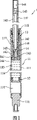
Fig. 3 is a three-dimensional exploded view of a preferred embodiment of shock absorber of the present utility model;
Fig. 4 is a combination cross-sectional schematic of this preferred embodiment, illustrates that a piston unit position is in a normal position;
Fig. 5 is the partial enlarged drawing of Fig. 4;
Fig. 6 is the view of similar Fig. 5, illustrates that this piston unit position is at a compression position.
Embodiment
Below in conjunction with drawings and Examples the utility model is elaborated:
As Fig. 3, Fig. 4 and shown in Figure 5, the preferred embodiment of the utility model shock absorber is between a seat cushion (figure does not show) and a skeleton (figure does not show) that is fixedly mounted in bicycle, and comprise: an earthen pipe unit 2, an Oil-gas Separation valve 3, a guide 4, and a piston unit 5.
This earthen pipe unit 2 comprises the outer tube 21 of a hollow upright, and this outer tube 21 has first end 211 that is positioned at the below, and second end 212 in contrast to first end 211.This earthen pipe unit 2 comprises that also a sealing is cemented in first end 211 of this outer tube 21 and the coupling seat 22 affixed with skeleton, and a secure bond is at the oil sealing base 23 of second end 212 of outer tube 21.
This Oil-gas Separation valve 3 is to be installed in the outer tube 21 with moving axially, with and 22 of the coupling seats of first end 211 define an airtight gas space 31, and define a fluid space 32 that does not communicate with the gas space 31 with 23 of the oil sealing bases of second end 212.
This guide 4 is the oil sealing bases 23 that are fixedly mounted in this fluid space 32 and are close to second end 212.
This piston unit 5 comprises that one can be installed in the fluid space 32 with moving axially, and be positioned at guide 4 and be connected piston 51 and the piston rod 52 of stretch through out the guide 4 and second end 212, and a snare is at the lining ring 53 of piston 51 peripheries with the piston 51, of 3 on Oil-gas Separation valve.This piston 51 is separated out fluid space 32 between first reserve of a contiguous Oil-gas Separation valve 3 321, and between second reserve of a contiguous guide 4 322.
This piston 51 has a sealing and plugs mounting hole 513, that plug splenium 511 in this outer tube 21, upwards axially runs through this shaft sleeve part 512 toward the shaft sleeve part 512, that guide 4 extends and diameter is smaller than plug splenium 511 by plug splenium 511 and axially run through plug splenium 511 and be communicated with between the mounting hole 513 and first reserve 321 first passage 514, reach a plurality of radially connect shaft sleeve part 512 and be communicated with first passage 514 and second reserve between 322 second channel 515.This piston rod 52 has one and axially is formed on away from the screw 521 in the end of piston 51, and one by screw 521 toward the axis of orientation of pistons 51 to the receiving hole 522 that runs through and be communicated with mounting hole 513.In design the quantity of second channel 515 can for one, more than two or two.This lining ring 53 has a lining ring body 531 that is nested in the annular groove 516 of plug splenium 511, and at least one outer circumferential face by lining ring body 53 1 axially is arranged with toward in and is communicated with between first and second reserve 321,322 passage 532.The section of this lining ring body 53 1 is square in the present embodiment, also can no longer describe in detail at this for circular, oval or other shapes in the design certainly.
And this piston unit 5 comprises that also one can be installed in control pins 54, in the mounting hole 513 with moving axially and stretches through in this receiving hole 522 and be resisted against actuating strut 55 on this control pin 54, reaches a screw 56 that can be screwed onto in this screw 521 with moving axially.What must further specify is, shock absorber is at coupling seat 22, oil sealing base 23, Oil-gas Separation valve 3, and the periphery of member such as control pin 54, is equipped with at least one O type ring of being made by rubber or silicon Li Kang 6 respectively, the function that it has sealing gland or oil sealing no longer illustrates at this.
In above-mentioned gas space 31, fill air, and in fluid space 32, pour into fluid.Before the use, can look use personage's body weight or road conditions earlier and adjust shock absorber pressure, just rotary screw 56 drives actuating strut 55, control this control pin 54 and shift near or move apart 514,515 in first and second passage, in order to control the size of 514,515 communication gap of two passages, but this is not an emphasis of the present utility model, so no longer describe in detail at this.
During action, this piston unit 5 can move between a normal position and a compression position with respect to earthen pipe unit 2, when shock absorber is subjected to external force, this piston unit 5 can be by the normal position of Fig. 4 and Fig. 5, the direction of past Oil-gas Separation valve 3 moves to the compression position as Fig. 6, the fluid of winning between reserve in 321 are squeezed, and have part fluid can be automatically passage 532 by lining ring 53 flow between second reserve 322.When external force disappears, this piston unit 5 will move toward second end 212 and be reset to the normal position, make between second reserve fluid in 322 be squeezed, the part fluid between this moment second reserve in 322, will be automatically passage 532 by lining ring 53 flow back between first reserve 321.
As shown in the above description, the design of the utility model shock absorber, mainly be to be provided with passage 532 at lining ring 53, allow fluid can be along with action access way 532 automatically, in order to keep the fluid density in the fluid space 32, noise can be do not produced,, the purpose of this utility model can be reached really so the utility model does not have the effect that noise produces in the time of can reaching action.
Claims (5)
1. shock absorber, comprise: an earthen pipe unit that comprises the outer tube of a hollow, the Oil-gas Separation valve that can be installed in the outer tube with moving axially, and piston unit, this outer tube has one first opposite end, and one second end, define a gas space between this Oil-gas Separation valve and first end, and and second end between define a fluid space, this piston unit comprises that one can be installed in the fluid space and the piston of second end of contiguous outer tube with moving axially, a piston rod that connects the piston and second end that stretches through out, reach the lining ring of a snare at the piston periphery, this piston is separated out fluid space between first reserve of a contiguous Oil-gas Separation valve, and between second reserve of vicinity second end, it is characterized in that: this lining ring has a lining ring body, and at least one axially is arranged with toward in and is communicated with first by the outer circumferential face of lining ring body, passage between two reserves.
2. shock absorber as claimed in claim 1 is characterized in that: the section of the lining ring body of this lining ring is square.
3. shock absorber as claimed in claim 1 or 2, it is characterized in that: this piston has one and plugs plug splenium in this outer tube, one and extended and diameter is smaller than the shaft sleeve part of plug splenium, mounting hole that axially runs through this shaft sleeve part, one and axially runs through the plug splenium and be communicated with first passage between the mounting hole and first reserve toward second end by the plug splenium, reach at least one radially connect shaft sleeve part and be communicated with first passage and second reserve between second channel.
4. shock absorber as claimed in claim 3, it is characterized in that: this piston rod has one and axially is formed on away from the screw in the end of piston, and one by screw toward the axis of orientation of piston to the receiving hole that runs through and be communicated with mounting hole, and this piston unit comprises that also one can be installed in control pin in the mounting hole, one with moving axially and stretches through in this receiving hole and be resisted against actuating strut on this control pin, reaches the screw that can be screwed onto in this screw with moving axially.
5. shock absorber as claimed in claim 1 is characterized in that: this shock absorber also comprises a guide that is fixedly mounted in this fluid space and is close to second end.
Priority Applications (1)
| Application Number | Priority Date | Filing Date | Title |
|---|---|---|---|
| CNU2007201764501U CN201106653Y (en) | 2007-09-13 | 2007-09-13 | Shock damper |
Applications Claiming Priority (1)
| Application Number | Priority Date | Filing Date | Title |
|---|---|---|---|
| CNU2007201764501U CN201106653Y (en) | 2007-09-13 | 2007-09-13 | Shock damper |
Publications (1)
| Publication Number | Publication Date |
|---|---|
| CN201106653Y true CN201106653Y (en) | 2008-08-27 |
Family
ID=39958455
Family Applications (1)
| Application Number | Title | Priority Date | Filing Date |
|---|---|---|---|
| CNU2007201764501U Expired - Fee Related CN201106653Y (en) | 2007-09-13 | 2007-09-13 | Shock damper |
Country Status (1)
| Country | Link |
|---|---|
| CN (1) | CN201106653Y (en) |
Cited By (1)
| Publication number | Priority date | Publication date | Assignee | Title |
|---|---|---|---|---|
| CN101839296B (en) * | 2010-01-13 | 2012-10-24 | 福州百特节能科技有限公司 | Springless shock absorber for automatically controlling damp and harvesting pulse hydraulic energy |
-
2007
- 2007-09-13 CN CNU2007201764501U patent/CN201106653Y/en not_active Expired - Fee Related
Cited By (1)
| Publication number | Priority date | Publication date | Assignee | Title |
|---|---|---|---|---|
| CN101839296B (en) * | 2010-01-13 | 2012-10-24 | 福州百特节能科技有限公司 | Springless shock absorber for automatically controlling damp and harvesting pulse hydraulic energy |
Similar Documents
| Publication | Publication Date | Title |
|---|---|---|
| CN101398053A (en) | Hydraulic shock absorber | |
| CN106015439B (en) | Big load Low rigidity velocity profile stopping means | |
| CN108343698A (en) | Damper | |
| CN203614510U (en) | Hydraulic buffering oil cylinder | |
| CN201739416U (en) | Shock damper | |
| CN104265824A (en) | Shock absorber | |
| CN104455184A (en) | Motorcycle inversed type front damper | |
| CN201106653Y (en) | Shock damper | |
| CN100497077C (en) | Minitype tricar and motorcycle front suspension | |
| CN204878500U (en) | Hydraulic absorber of multistage damping throttle | |
| CN201714896U (en) | Piston valve of vibration absorber of rail vehicle | |
| JP5660667B2 (en) | Front fork | |
| CN104251277A (en) | Large-connecting-rod two-grade buffering shock absorber | |
| CN104500636A (en) | Sensing variable-frequency vibration absorber | |
| CN209800611U (en) | damping device for centrifuge | |
| CN104358735B (en) | A kind of lifting hydraulic jack | |
| CN212954085U (en) | Hydraulic device with buffering function | |
| CN208331099U (en) | Damper | |
| CN107477133A (en) | A kind of single-piston rod hydraulic damper | |
| CN201621223U (en) | Shock absorber hydraulic cushion mechanism | |
| CN202108477U (en) | Plunger water pumping gas production well mouth buffer | |
| CN207018416U (en) | Marine riser damping with Vibrant buffer function is single | |
| CN206592099U (en) | Anti- return of one kind tells ball-and-seat | |
| CN204300219U (en) | A kind of inversion type front damping device for motorcycle | |
| CN206036106U (en) | Big load low rigidity velocity profile stop device |
Legal Events
| Date | Code | Title | Description |
|---|---|---|---|
| C14 | Grant of patent or utility model | ||
| GR01 | Patent grant | ||
| C17 | Cessation of patent right | ||
| CF01 | Termination of patent right due to non-payment of annual fee |
Granted publication date: 20080827 Termination date: 20091013 |