CN201059629Y - Special warm-air equipment for gasifying stove - Google Patents
Special warm-air equipment for gasifying stove Download PDFInfo
- Publication number
- CN201059629Y CN201059629Y CNU2007202003508U CN200720200350U CN201059629Y CN 201059629 Y CN201059629 Y CN 201059629Y CN U2007202003508 U CNU2007202003508 U CN U2007202003508U CN 200720200350 U CN200720200350 U CN 200720200350U CN 201059629 Y CN201059629 Y CN 201059629Y
- Authority
- CN
- China
- Prior art keywords
- housing
- chamber
- shell
- special
- air
- Prior art date
- Legal status (The legal status is an assumption and is not a legal conclusion. Google has not performed a legal analysis and makes no representation as to the accuracy of the status listed.)
- Expired - Fee Related
Links
Images


Abstract
The utility model relates to the air heater technical field used for heating, in particular to an air heater specially used by a gasification furnace, comprising a gas tank and a shell, wherein, a gas inlet pipe is arranged on the gas tank; the shell is arranged on the gas tank; a shell base is arranged between the gas tank and the shell; a combustion chamber is arranged at the bottom of the shell; a shell air inlet is arranged on the shell base; the gas tank is communicated with the combustion chamber through the shell air inlet; an igniter capsule is arranged on the shell air inlet; a smoke collection chamber is arranged on the top of the shell; a smoke vent pipe is arranged on the upper part of the shell and communicated with the smoke collection chamber; a fire passing pipe is arranged between the combustion chamber and the smoke collection chamber which are communicated with each other through the fire passing pipe; an air heating cavity is formed between the fire passing pipe and the shell; an air inlet and an air outlet are arranged on the shell and communicated with the air heating cavity. The utility model has the advantages of reasonable and compact structure, convenient use, capability of quick and effective emission, great improvement of thermal efficiency, and quite significant energy saving effect, and is especially suitable for heating in winter.
Description
One, technical field
The utility model relates to the fan heater technical field that is used for heating, is the special-purpose fan heater of a kind of gasification furnace.
Two, background technology
At present, rural area domestic heating stove product kind is various, it generally is main fuel with the coal, by adding hot water is that thermaltransmission mode heats, disposable energy the consumption of coal is bigger, long and cold in the winter time area, hot-water heating all can not leave the people in whole very long use in winter, otherwise can be because of lacking the flame-out and freezing heating pipeline of coal.
Existing fan heater generally adopts electricity to be the energy, but because the electrical power of electric calorifier is big, so the electricity cost height, can not satisfy the needs of urban residents as daily heating instrument.
Three, summary of the invention
The utility model provides a kind of gasification furnace special-purpose fan heater, has overcome the deficiency of above-mentioned prior art, has the high characteristics of the thermal efficiency, and hot blast can be provided effectively.
The technical solution of the utility model realizes by following measure: the special-purpose fan heater of a kind of gasification furnace, and it comprises combustion gas casing and housing; The combustion gas inlet pipe is arranged on the combustion gas casing; Housing is positioned on the combustion gas casing, and the housing pedestal is arranged between combustion gas casing and housing; At the bottom of housing combuster; On the housing pedestal, there is shell air inlet that gas box is communicated with the combustion chamber; There is igniter cap at the place in shell air inlet; Fume collecting chamber is arranged at the top at housing, smoke exhaust pipe is arranged on the top of housing and is connected with fume collecting chamber; Between combustion chamber and fume collecting chamber, there was fire tube that the combustion chamber is communicated with fume collecting chamber; Cross and form the air heat chamber between fire tube and the housing, on housing, have air inlet and air outlet to be communicated with the air heat chamber.
Be further optimization and/or improvements below to above-mentioned technical solutions of the utility model:
Be set with the medium pillar above-mentioned the mistake on the fire tube, cross and form the dielectric layer that to adorn heat transfer medium between fire tube and the medium pillar.
Following dielectric chamber can be arranged at the bottom at above-mentioned dielectric layer, and last dielectric chamber is arranged at the top of dielectric layer.
On the dielectric chamber corresponding shell medium indicating window that communicates with last dielectric chamber can be installed on above-mentioned.
On above-mentioned medium indicating window, Freeing Pipe can be installed.
At the above-mentioned fire tube of crossing or/and can there be the heat transfer lamellar body in the outside of medium pillar.
In the housing of above-mentioned air inlet one side, air uniform plate can be arranged, the even wind hole that air inlet is connected with the air heat chamber is arranged on air uniform plate.
On the housing of above-mentioned igniter cap Zhou Duan, seat clay can be arranged.
On the corresponding shell of above-mentioned combustion chamber, the observation flap can be installed.
On above-mentioned housing, heat-insulation layer can be arranged.
The utility model reasonable and compact in structure, easy to use, heat can fast and effeciently distribute, and has greatly improved the thermal efficiency, and the energy-saving effect highly significant can provide hot blast effectively, is specially adapted to winter heating.
Four, description of drawings
Accompanying drawing 1 is the main TV structure schematic diagram of the utility model most preferred embodiment,
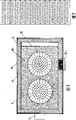
Accompanying drawing 2 be the A-A of accompanying drawing 4 to the sectional structure schematic diagram,
Accompanying drawing 3 be the B-B of accompanying drawing 1 to the sectional structure schematic diagram,
Accompanying drawing 4 is the plan structure schematic diagram of the utility model most preferred embodiment,
Accompanying drawing 5 be the C-C of accompanying drawing 4 to the sectional structure schematic diagram,
Accompanying drawing 6 be the D-D of accompanying drawing 1 to the sectional structure schematic diagram,
Accompanying drawing 7 is the structural representation of air uniform plate in the accompanying drawing 2,
Accompanying drawing 8 is the right view of accompanying drawing 1,
Accompanying drawing 9 is the left view of accompanying drawing 1;
Coding in the accompanying drawing is respectively: 1 is the combustion gas inlet pipe, and 2 are the combustion gas casing, and 3 is the housing pedestal, and 4 is igniter cap, 5 is the combustion chamber, and 6 was fire tube, and 7 are following dielectric chamber, and 8 is the medium pillar, 9 is dielectric layer, and 10 is air uniform plate, and 11 is air inlet, and 12 are the heat transfer lamellar body, 13 is heat-insulation layer, and 14 is housing, and 15 is air outlet, and 16 is last dielectric chamber, 17 is fume collecting chamber, and 18 is the medium indicating window, and 19 is Freeing Pipe, 20 is smoke exhaust pipe, and 21 for observing flap, and 22 is seat clay.
Five, the specific embodiment
The utility model is not subjected to the restriction of following embodiment, can determine concrete embodiment according to the technical solution of the utility model and actual conditions.
Below in conjunction with embodiment and accompanying drawing the utility model is further described:
Shown in accompanying drawing 1 to 9, the special-purpose fan heater of this gasification furnace comprises combustion gas casing 2 and housing 14; Combustion gas inlet pipe 1 is arranged on combustion gas casing 2; Housing 14 is positioned on the combustion gas casing 2, between combustion gas casing 2 and housing 14 housing pedestal 3 is arranged; At the bottom of housing 14 combuster 5; On housing pedestal 3, there is shell air inlet that combustion gas casing 2 is communicated with combustion chamber 5; At the shell air inlet place igniter cap 4 is arranged; At the top of housing 14 fume collecting chamber 17 is arranged, smoke exhaust pipe 20 is arranged on the top of housing 14 and be connected with fume collecting chamber 17; Between combustion chamber 5 and fume collecting chamber 17, there was fire tube 6 that combustion chamber 5 is communicated with fume collecting chamber 17; Cross and form the air heat chamber between fire tube 6 and the housing 14, on housing 14, have air inlet 11 and air outlet 15 to be communicated with the air heat chamber.
Can according to actual needs the special-purpose fan heater of above-mentioned gasification furnace be made further optimization and/or improvements:
In order further to improve the thermal efficiency, shown in accompanying drawing 2,3 and 5, be set with medium pillar 8 crossing on the fire tube 6, cross the dielectric layer 9 that formation between fire tube 6 and the medium pillar 8 can be adorned heat transfer medium; Following dielectric chamber 7 is arranged at the bottom of dielectric layer 9, and last dielectric chamber 16 is arranged at the top of dielectric layer 9, thereby helps the circulation of heat transfer medium; Shown in accompanying drawing 2,3, the capacity for control heat transfer medium in the use is equipped with the medium indicating window 18 that communicates with last dielectric chamber 16 on last dielectric chamber 16 corresponding shell 14; Shown in accompanying drawing 1,2,, Freeing Pipe 19 is installed on medium indicating window 18 in order to prevent the medium expanded by heating and to be convenient in dielectric layer 9, add heat transfer medium; In order to increase heat transfer area, shown in accompanying drawing 2 and 5, heat transfer lamellar body 12 is arranged in (cross fire tube or/and) medium pillar 8 outsides; For the wind regime that air inlet 11 is come in is blown into the air heat chamber equably, air uniform plate 10 is arranged in the housing of air inlet 11 1 sides, the even wind hole that air inlet 11 is connected with the air heat chamber is arranged on air uniform plate 10.When the utility model does not have medium pillar 8 and dielectric layer 9 thereof, the heat transfer lamellar body is arranged in the outside of crossing fire tube 6.
Shown in accompanying drawing 2,3,, on the housing pedestal 3 of 5 week of igniter cap end, seat clay 22 is arranged in order to reduce the loss of heat energy.
For the ease of observing the situation of combustion chamber 5 internal combustion, shown in accompanying drawing 1,3,4, be equipped with on 5 corresponding shell of combustion chamber and observe flap 21.
Shown in accompanying drawing 2,3 and 5, on the housing 14 heat-insulation layer is arranged, thereby reduce the loss of heat.
Above technical characterictic has constituted most preferred embodiment of the present utility model, and it has stronger adaptability and best implementation result, can increase and decrease non-essential technical characterictic according to actual needs, satisfies the demand of different situations.
The concrete application of the utility model most preferred embodiment is as follows: preferably earlier air inlet 11 of the present utility model is connected on the air outlet of blower fan; The air mixture that enters into combustion gas casing 2 by combustion gas inlet pipe 1 through igniter cap 4 in the combustion chamber 5 internal combustion, the combustion fire at first directly heats following dielectric chamber 7 bottoms, medium is heated, ember is crossed fire tube 6 medium on every side through 6 pairs of fire tubes and heated back arrival fume collecting chamber 17 again, and is outdoor by being discharged from behind the smoke exhaust pipe 20 then; Medium is in the dielectric cavity of crossing between fire tube 6 and the medium pillar 8, and medium by the dielectric cavity conducting, leans on the temperature difference and deadweight to circulate up and down between last dielectric chamber 16 and following dielectric chamber 7, heat transfer lamellar body 12 that heat transferred medium pillar 8 is outer after the medium heating; The wind regime that is transmitted by blower fan enters through air uniform plate 10 from air inlet 11 and to adjust after-blow to heat transfer lamellar body 12, and wind becomes hot blast after with the heat fast Absorption on the heat transfer lamellar body 12, and hot blast is sent into indoor through air outlet 15 by pipeline.
Claims (10)
1. the special-purpose fan heater of gasification furnace is characterized in that comprising combustion gas casing and housing; The combustion gas inlet pipe is arranged on the combustion gas casing; Housing is positioned on the combustion gas casing, and the housing pedestal is arranged between combustion gas casing and housing; At the bottom of housing combuster; On the housing pedestal, there is shell air inlet that gas box is communicated with the combustion chamber; There is igniter cap at the place in shell air inlet; Fume collecting chamber is arranged at the top at housing, smoke exhaust pipe is arranged on the top of housing and is connected with fume collecting chamber; Between combustion chamber and fume collecting chamber, there was fire tube that the combustion chamber is communicated with fume collecting chamber; Cross and form the air heat chamber between fire tube and the housing, on housing, have air inlet and air outlet to be communicated with the air heat chamber.
2. the special-purpose fan heater of gasification furnace according to claim 1 is characterized in that being set with on the fire tube medium pillar, crossed and formed the dielectric layer that can adorn heat transfer medium between fire tube and the medium pillar.
3. the special-purpose fan heater of gasification furnace according to claim 2 is characterized in that following dielectric chamber is arranged at the bottom of dielectric layer, and last dielectric chamber is arranged at the top of dielectric layer.
4. the special-purpose fan heater of gasification furnace according to claim 3 is characterized in that being equipped with on the dielectric chamber corresponding shell medium indicating window that communicates with last dielectric chamber.
5. the special-purpose fan heater of gasification furnace according to claim 4 is characterized in that on the medium indicating window Freeing Pipe being installed.
6. according to claim 1 or the special-purpose fan heater of 2 or 3 or 4 or 5 described gasification furnaces, it is characterized in that fire tube or/and there is the heat transfer lamellar body in the outside of medium pillar.
7. the special-purpose fan heater of gasification furnace according to claim 6 is characterized in that in the housing of air inlet one side air uniform plate being arranged, and the even wind hole that air inlet is connected with the air heat chamber is arranged on air uniform plate.
8. the special-purpose fan heater of gasification furnace according to claim 7 is characterized in that on the housing of igniter cap Zhou Duan seat clay being arranged.
9. the special-purpose fan heater of gasification furnace according to claim 8 is characterized in that being equipped with on the corresponding shell of combustion chamber the observation flap.
10. the special-purpose fan heater of gasification furnace according to claim 9 is characterized in that heat-insulation layer is arranged on the housing.
Priority Applications (1)
| Application Number | Priority Date | Filing Date | Title |
|---|---|---|---|
| CNU2007202003508U CN201059629Y (en) | 2007-05-10 | 2007-05-10 | Special warm-air equipment for gasifying stove |
Applications Claiming Priority (1)
| Application Number | Priority Date | Filing Date | Title |
|---|---|---|---|
| CNU2007202003508U CN201059629Y (en) | 2007-05-10 | 2007-05-10 | Special warm-air equipment for gasifying stove |
Publications (1)
| Publication Number | Publication Date |
|---|---|
| CN201059629Y true CN201059629Y (en) | 2008-05-14 |
Family
ID=39408103
Family Applications (1)
| Application Number | Title | Priority Date | Filing Date |
|---|---|---|---|
| CNU2007202003508U Expired - Fee Related CN201059629Y (en) | 2007-05-10 | 2007-05-10 | Special warm-air equipment for gasifying stove |
Country Status (1)
| Country | Link |
|---|---|
| CN (1) | CN201059629Y (en) |
Cited By (3)
| Publication number | Priority date | Publication date | Assignee | Title |
|---|---|---|---|---|
| CN103322673A (en) * | 2013-06-19 | 2013-09-25 | 刘旺 | Oil/natural-gas-fired hot-blast environment-friendly boiler |
| CN104061776A (en) * | 2014-06-24 | 2014-09-24 | 广西壮族自治区桂林茶叶科学研究所 | Hot-gas generating device for drying tea leaves |
| CN112902448A (en) * | 2021-02-02 | 2021-06-04 | 任堃 | Heat accumulating type air heating furnace and heating system thereof |
-
2007
- 2007-05-10 CN CNU2007202003508U patent/CN201059629Y/en not_active Expired - Fee Related
Cited By (4)
| Publication number | Priority date | Publication date | Assignee | Title |
|---|---|---|---|---|
| CN103322673A (en) * | 2013-06-19 | 2013-09-25 | 刘旺 | Oil/natural-gas-fired hot-blast environment-friendly boiler |
| CN104061776A (en) * | 2014-06-24 | 2014-09-24 | 广西壮族自治区桂林茶叶科学研究所 | Hot-gas generating device for drying tea leaves |
| CN104061776B (en) * | 2014-06-24 | 2016-06-01 | 广西壮族自治区桂林茶叶科学研究所 | A kind of hot gas generating unit drying tealeaves |
| CN112902448A (en) * | 2021-02-02 | 2021-06-04 | 任堃 | Heat accumulating type air heating furnace and heating system thereof |
Similar Documents
| Publication | Publication Date | Title |
|---|---|---|
| CN101430102B (en) | Biomass shaping fuel-combustion countryside cooking/bathing/heating integrated apparatus | |
| CN201508017U (en) | Improved gas water heater | |
| CN202229164U (en) | Condensing type steam boiler energy-saving heating device | |
| CN201059629Y (en) | Special warm-air equipment for gasifying stove | |
| CN102966978B (en) | Solid and gas multi-fuel water stove | |
| CN103017328A (en) | Combustion and heat exchange system of heating equipment | |
| CN102330966B (en) | Energy-saving heat-supplying device of condensation steam boiler | |
| CN104748367B (en) | The dustless hot air boiler of Superstrong energy-saving | |
| CN102012046A (en) | Convection heating Kang | |
| CN201508036U (en) | Direct-combustion tube-typed split organic heat carrier boiler | |
| CN201259306Y (en) | High-efficiency water-heating boiler | |
| CN202915405U (en) | Energy-saving environment-friendly heating furnace | |
| CN209310262U (en) | A kind of heating heat recovery boiler | |
| CN201909346U (en) | Convection type heating heated kang | |
| CN201289216Y (en) | Full-wet vacuum boiler | |
| CN203131879U (en) | Multi-fuel water heating furnace capable of burning solids and gases | |
| CN104676656A (en) | Energy-saving environment-friendly domestic heating boiler | |
| CN201059753Y (en) | Water heater special for gasifying stove | |
| CN204478465U (en) | Fin panel casing compound backwater condensing natural gas hot water boiler | |
| CN201463221U (en) | Fast hot water generator | |
| CN201377908Y (en) | Normal pressure multi-purpose pneumatic conveying heating boiler | |
| CN203052976U (en) | Combustion and heat exchange system of heating equipment | |
| CN2738159Y (en) | Efficient energy-saving water heater | |
| CN201514036U (en) | High-efficiency energy-saving gas-fired boiler | |
| CN202709081U (en) | Energy-saving type steam heating furnace |
Legal Events
| Date | Code | Title | Description |
|---|---|---|---|
| C14 | Grant of patent or utility model | ||
| GR01 | Patent grant | ||
| C17 | Cessation of patent right | ||
| CF01 | Termination of patent right due to non-payment of annual fee |
Granted publication date: 20080514 Termination date: 20100510 |