CN201023666Y - Plastic hose filling machine - Google Patents
Plastic hose filling machine Download PDFInfo
- Publication number
- CN201023666Y CN201023666Y CNU2007200363551U CN200720036355U CN201023666Y CN 201023666 Y CN201023666 Y CN 201023666Y CN U2007200363551 U CNU2007200363551 U CN U2007200363551U CN 200720036355 U CN200720036355 U CN 200720036355U CN 201023666 Y CN201023666 Y CN 201023666Y
- Authority
- CN
- China
- Prior art keywords
- frame
- flexible pipe
- afterbody
- sealing
- rotating disk
- Prior art date
- Legal status (The legal status is an assumption and is not a legal conclusion. Google has not performed a legal analysis and makes no representation as to the accuracy of the status listed.)
- Expired - Fee Related
Links
Images
Abstract
A plastic flexible pipe filling equipment belongs to a filling mechanic, in particular to a device used for filling articles into the plastic flexible pipe. According to the technical scheme provided by the utility model, a portion charging component is arranged on the left side of the frame, a rotary disk is arranged on the right side of the frame, a plurality of locating clamps of unfilled flexible pipes for locating are arranged on the rotary disk, a filling component, an inner heating component, an outer heating component, a tail sealing component and a cutting edge component which are arranged on the upper part of the rotary disk are sequentially arranged along the rotating direction of the rotary disk, the lower part of the frame is equipped with a driven component, an interval stirring component which is used for the interval stirring of the rotary disk is arranged between the first power outlet of the driven component and the rotary disk, a cam component which is arranged on the second power outlet of the driven component is used for stirring a plurality of directional selecting valves. The utility model has the advantages of being capable of conveniently filling materials into the flexible pipes, and reducing the cost of the filling equipment.
Description
Technical field
The utility model belongs to a kind of filling machine, refers in particular to a kind of device that is used for can article in plastic hose.
Background technology
Bottle placer is to be mainly used in can lotion class material in package tube.The most dependence on import of bottle placer of present China, so cost is than higher; Simultaneously, the structure of employing is more complicated also, breaks down easily in process of production, quite bothers when operating in addition.
Summary of the invention
The purpose of this utility model is to design a kind of plastic hose bottle placer, with convenience can material in flexible pipe, and the cost of reduction bottle placer.
According to the technical scheme that the utility model provides, in the left side of frame quantifying feed mechanism is installed, in the right upper portion of frame rotating disk is installed, several are installed on rotating disk are used to locate the positioning fixture of flexible pipe to be filled; On the frame above the rotating disk, along the rotation direction of rotating disk set gradually be used for to flexible pipe to be filled pour into material filling mechanism, be used for interior heating arrangements that the afterbody inwall to flexible pipe heats, the outer heating mechanism that is used for that afterbody outer wall to flexible pipe heats, be used for the sealing mechanism of the afterbody sealing of flexible pipe and be used to excise the trimming mechanism of the redundance of flexible pipe afterbody; Driver train is installed in bottom in frame, between first clutch end of this driver train and rotating disk, be provided for intermittently stirring the toggle mechanism at intermittence of rotating disk, second clutch end at driver train is provided with cam mechanism, this cam mechanism is used to stir several change-over valves, and each change-over valve is used to control cooresponding filling mechanism, interior heating arrangements, heats the course of action of mechanism or sealing mechanism outward.
In driver train, motor mounting is in the bottom of frame, and the mouth of electrical motor utilizes belt to interconnect with the reductor that is installed on the frame bottom equally.In the intermittence toggle mechanism, the calibration sheave is installed on the lower end of rotating shaft, several radial grooves are set on the calibration sheave, on this groove, has the opening that allows to stir in the shift fork insertion groove calibration sheave, shift fork is installed on the runner, and runner utilizes transmission device to be connected with first clutch end of driver train; Rotating shaft is installed on the rotating disk.In cam mechanism, several cams are installed on second clutch end of driver train, and each cam is used to stir cooresponding change-over valve.
In quantifying feed mechanism, metering cylinder is installed on the frame, on the frame above the metering cylinder, plunger pump is installed, the piston rod of metering cylinder is connected with the lower end of plunger pump, charging basket is installed in upper end at plunger pump, between the bottom of plunger pump and filling mechanism, utilize connection pipe to interconnect, the travel switch on the frame of being installed on is arranged in the stroke range corresponding to piston rod; Between travel switch and frame, be provided for the regulating mechanism of adjustment travel switch with respect to the position of piston rod.In filling mechanism, can is chewed lift cylinders and is installed on the frame, chews in can is installed on the piston rod of lift cylinders chews, and between the exit end of entrance point that can is chewed and plunger pump connection pipe is set.
In interior heating arrangements, interior heat driven valve is installed on the frame of rotating disk top, heating push rod in interior heat driven valve has, heating head in install the lower end of interior heating push rod, the electric heater and the thermal current outlet that can extend in the flexible pipe afterbody are set in interior heating head, and the thermal current outlet is connected with air supply pipe.Outside in the heating arrangements, outer heating driving valve is installed on the frame of rotating disk top, adding of outer heating driving valve picks the outer heating head of bar lower end installation, should when heating hose, allow the afterbody of flexible pipe to insert in it by outer heating head, two relative electric heaters are arranged in the heating head outside, electric heater and outside be provided for driving the travel mechanism that two electric heaters close up between heating head, two electric heaters are clamped the afterbody of flexible pipe when heating hose, make the afterbody of flexible pipe become Long Circle from sub-circular.
In sealing mechanism, the sealing valve is installed on the frame of rotating disk top, has the sealing push rod that can stretch on the sealing valve, in the lower end of sealing push rod the sealing chuck is set, in the sealing chuck, be provided with allow the flexible pipe afterbody to insert the space in it and be used for two of clamping flexible pipe afterbody relative and can draw close mutually and the fixture block that separates, between fixture block and sealing chuck, be provided for driving the clamping device that the flexible pipe afterbody was clamped and oppressed to fixture block.
In trimming mechanism, the cutting knife valve is installed on the frame, the side cut bar that can stretch is arranged on the cutting knife valve, mobile cutting knife is installed on the side cut bar, corresponding position in frame installs and fixes cutting knife, the blade of mobile cutting knife cooperatively interacts with the blade of fixed cutting tool when the redundance of cutting flexible pipe afterbody; Position corresponding to trimming mechanism on frame is provided with ejecting mechanism; In ejecting mechanism, liftout tank is installed on the frame, and the knock-pin that can move up and down is arranged on the liftout tank, inserts when knock-pin rises in the anchor clamps on the rotating disk, and the flexible pipe of having cut edge is ejected from its anchor clamps; On the frame below the trimming mechanism, be provided for collecting the aggregate bin of leftover pieces.
The utility model has the advantages that: course of action mainly adopts transmission principle one time, utilizes the indexing trough wheel mechanism to drive to be equipped with the rotating disk of anchor clamps to make intermittent moment, finishes a series of functions such as auto-filling and inside and outside heating, sealing, pressure sign indicating number, side cut, finished product withdraw from.Therefore it is accurate to have filling measurement, and time of heat is stable, adjustable, and the sealing outward appearance is beautiful, neat, firm, health.It is smooth standardized to cut edge.This machine is made as 10 stations altogether, goes up the pipe except that artificial, and other all can be finished automatically.Complete machine operates steadily reliably, noiselessness and other pollutions.
The all contact materials of complete machine and some region of interest all adopt high chrome stainless steel to make, and need to clean the position and all select fast replacing device for use, unpick and wash conveniently.When some material needed heat tracing, its charging basket outside can install heating constant-temperature equipment additional.This device is applicable to cosmetic industry, medicine trade, adhesive industry, shoe polish industry, and other relevant industries, can material in plastic pipe comprises multiple unit tube.
Description of drawings
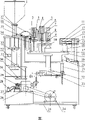
Fig. 1 is a constructional drawing of the present utility model.
The specific embodiment
Among the figure: 1, charging basket, be used to store material, 2, interior heat driven valve, 3, interior heating head, utilize the gentle hotsync that adds of electro heat that hose inner wall is heated, can under the drive of interior heat driven valve 2, extend in the flexible pipe, but afterbody is heated to sealing temperature, 4, air supply pipe, thermal current is provided, 5, outer heating driving valve, 6, the sealing valve, 7, add and pick bar, 8, the sealing push rod, 9, outer heating head realizes that with the heating of flexible pipe outer wall the tube wall internal and external temperature is heated evenly, outside under the drive of heat driven valve 5, can extend the flexible pipe outside, outer wall to flexible pipe heats, and 10, the sealing chuck is with the flexible pipe compacting after the heating, and printing production batch and date steel sign indicating number, 11, the side cut frame, 12, the side cut bar, 13, mobile cutting knife, with the unnecessary whole branch excisions of the flexible pipe that has sealed, 14, the cutting knife valve, 15, fixed cutting tool, 16, flexible pipe, 17, hose clamp, 18, rotating disk is used to install the anchor clamps of clamping flexible pipe, 19, aggregate bin, 20, knock-pin, the flexible pipe of embedding moulding is ejected anchor clamps, realize unloading automatically pipe, 21, liftout tank, 22, rotating shaft, be used to connect sheave and rotating disk, sheave drives rotating disk by rotating shaft and intermittently rotates 23, the calibration sheave utilizes indexing mechanism to realize the calibration revolution of flexible pipe, 24, electrical motor, 25, frame, 26, reductor, 27, change-over valve, 28, the two-position three way pilot solenoid valve, 29, distributor, 30, travel switch, 31, adjust bar, 32, electrical apparatus control system, 33, metering cylinder is regulated pump housing metering, makes to meet the can requirement, 34, can is chewed, 35, the fill head lift cylinders, chew can in the tubular stinger after can again, it is excessive to protect material, 36, plunger pump, be used for material being filled in the flexible pipe 37, connection pipe, 38, support.
As shown in the figure: quantifying feed mechanism is installed in the left side in frame 25, in the right upper portion of frame 25 rotating disk 18 is installed, and several is installed on rotating disk 18 is used to locate the positioning fixture 17 of flexible pipe to be filled; On the frame above the rotating disk 18 25, along the rotation direction of rotating disk 18 set gradually be used for to flexible pipe to be filled pour into material filling mechanism, be used for interior heating arrangements that the afterbody inwall to flexible pipe heats, the outer heating mechanism that is used for that afterbody outer wall to flexible pipe heats, be used for the sealing mechanism of the afterbody sealing of flexible pipe and be used to excise the trimming mechanism of the redundance of flexible pipe afterbody; Driver train is installed in bottom in frame 25, between first clutch end of this driver train and rotating disk 18, be provided for intermittently stirring the toggle mechanism at intermittence of rotating disk, second clutch end at driver train is provided with cam mechanism, this cam mechanism is used to stir several change-over valves, and each change-over valve is used to control cooresponding filling mechanism, interior heating arrangements, heats the course of action of mechanism or sealing mechanism outward.
In driver train, electrical motor 24 is installed on the bottom of frame 25, and the mouth of electrical motor 24 utilizes belt to interconnect with the reductor 26 that is installed on frame 25 bottoms equally.In the intermittence toggle mechanism, calibration sheave 23 is installed on the lower end of rotating shaft 22, several radial grooves are set on calibration sheave 23, on this groove, has the opening that allows to stir in the shift fork insertion groove calibration sheave 23, shift fork is installed on the runner, and runner utilizes transmission device to be connected with first clutch end of driver train; Rotating shaft 22 is installed on the rotating disk 18.In cam mechanism, several distributors 29 are installed on second clutch end of driver train, and each cam is used to stir cooresponding change-over valve 27.During work, all cans, inside and outside heating, sealing, operation such as cut edge, eject and finish required action by distributor 29, two-position three way pilot solenoid valve 28 and change-over valve 27 controls, whole working condition operates steadily, the repetition performance is good, the action arrival rate can reach 100%, none error, safe and reliable, easy and simple to handle.
In quantifying feed mechanism, metering cylinder 33 is installed on the frame 25, plunger pump 36 is installed on the frame above the metering cylinder 33 25, the piston rod of metering cylinder 33 is connected with the lower end of plunger pump 36, charging basket 1 is installed in upper end at plunger pump 36, between the bottom of plunger pump 36 and filling mechanism, utilize connection pipe 37 to interconnect, the travel switch 30 on frame of being installed on 25 is arranged in the stroke range corresponding to piston rod; The regulating mechanism that is provided for adjustment travel switch 30 with respect to the position of piston rod in travel switch 30 and 25 of frames.In filling mechanism, can is chewed lift cylinders 35 and is installed on the frame 25, chews in can is installed on the piston rod of lift cylinders 35 chews 34, chews in can between the exit end of 34 entrance point and plunger pump 36 connection pipe 37 is set.
In interior heating arrangements, interior heat driven valve 2 is installed on the frame 25 of rotating disk 18 tops, heating push rod in interior heat driven valve 2 has, heating head 3 in install the lower end of interior heating push rod, the electric heater and the thermal current outlet that can extend in the flexible pipe afterbody are set in interior heating head 3, and the thermal current outlet is connected with air supply pipe 4.Electric heater adopts the electric heating copper billet, and when utilizing the electric heater heating, hot blast makes the hose inner wall thermally equivalent by jet pipe.Than only adopting the method advanced person of flexible pipe external heat many in the past.The fastness of sealing also is improved largely.Two kinds of methods are compared, and when only using outer heating, toward interior heat, inside and outside error is big from the outside for tube wall, and particularly the hose inner wall temperature is lower than outer wall certainly, and in sealing with press in the sign indicating number process, often causing adhesion or sealing fastness instability also is a big defective.The utility model adopts inside and outside method of heating, makes the tube wall internal and external temperature basic identical, has overcome the defective of original simple outer heating fully, has improved sealing and has pressed the sign indicating number quality.
Outside in the heating arrangements, outer heating driving valve 5 is installed on the frame 25 of rotating disk 18 tops, adding of outer heating driving valve 5 picks the outer heating head 9 of bar 7 lower ends installation, should when heating hose, allow the afterbody of flexible pipe to insert in it by outer heating head 9, two relative electric heaters are arranged in the heating head 9 outside, electric heater and outside 9 of heating heads be provided for driving the travel mechanism that two electric heaters close up, two electric heaters are clamped the afterbody of flexible pipe when heating hose, make the afterbody of flexible pipe become Long Circle from sub-circular.Two electric heaters that should heat outward in the mechanism adopt the reciprocating type pressing principles of scissors, having carried out the good flexible pipe of direct heating again at the tube wall external heat through the upper track station, make the hose wall heating condition obtain further to improve, for sealing, the pressure sign indicating number of back have been created very perfect involution condition.
In sealing mechanism, sealing valve 6 is installed on the frame 25 of rotating disk 18 tops, has the sealing push rod 8 that can stretch on the sealing valve 6, in the lower end of sealing push rod 8 sealing chuck 10 is set, in sealing chuck 10, be provided with allow the flexible pipe afterbody to insert the space in it and be used for two of clamping flexible pipe afterbody relative and can draw close mutually and the fixture block that separates, be provided for driving the clamping device that the flexible pipe afterbody was clamped and oppressed to fixture block at fixture block and 10 of sealing chucks.The same employing of sealing mechanism drives reciprocating type shear mechanism by the sealing valve, and flexible pipe (multiple unit tube) pressing of having heated is sealed, and scribes information such as product batch number on the sealing chuck, in use, and can be by product batch number and date transposing steel seal.Because the equilibrium of flexible pipe internal and external temperature, institute's sealing is very clear firmly, and can bear sizable internal pressure.The disengagement of also can not breaking has guaranteed the quality and prestige of consumer products simultaneously, and this also is that all users are desirable.
In trimming mechanism, cutting knife valve 14 is installed on the frame 25, the side cut bar 12 that can stretch is arranged on cutting knife valve 14, mobile cutting knife 13 is installed on side cut bar 12, corresponding position in frame 25 installs and fixes cutting knife 16, the blade of mobile cutting knife 13 cooperatively interacts with the blade of fixed cutting tool 16 when the redundance of cutting flexible pipe afterbody; Position corresponding to trimming mechanism on frame 25 is provided with ejecting mechanism; In ejecting mechanism, liftout tank 21 is installed on the frame 25, and the knock-pin 20 that can move up and down is arranged on the liftout tank 21, in the anchor clamps 17 when knock-pin 20 rises on the insertion rotating disk 18, the flexible pipe of having cut edge is ejected from its anchor clamps 17; On the frame below the trimming mechanism 25, be provided for collecting the aggregate bin 19 of leftover pieces.After sign indicating number was pressed in flexible pipe (multiple unit tube) sealing, the tail end position was not necessarily all uniform, so the processing of must cutting edge.This device has a slice fixed cutting tool 16 and a slice to be driven by the cutting knife valve and the mobile cutting knife that has a constant slope carries out back-end crop, makes the product tail end uniform, attractive in appearance, has improved the external form ornamental of consumer products.
During work, electrical motor 24 provides power, through worm reduction gear 26 and after carrying out frequency control, driving a pair of cylindrical wheel by a pair of bevel gear earlier rotates, do intermittent duty by being installed on a shift fork drive calibration sheave 23 on the cylindrical wheel again, drive rotating disk 18 by calibration sheave 23 by rotating shaft 22 and do discontinuous running, make 10 anchor clamps that are contained on the rotating disk 18 make isogonism and rotate.The distributor 29 that is installed on simultaneously on the motor rotary shaft is dialed cooresponding change-over valve 27 successively, by cooresponding each actuating unit of two-position three way pilot solenoid valve control, described actuating unit is by change-over valve 27: quantifying feed mechanism, filling mechanism, interior heating arrangements, heat mechanism, sealing mechanism and ejecting mechanism outward.
By manually flexible pipe being inserted in the anchor clamps 17, make flexible pipe obtain good location then.Be that the can station carries out can at first station earlier; When can, quantifying feed mechanism adopts metering cylinder 33 to drive, the plunger that is driven in the plunger pump 36 by metering cylinder 33 moves up and down, material in the hopper is chewed 34 by the can that connection pipe 37 is delivered in the filling mechanism, before 34 beginning cans are chewed in can, can is chewed 34 and is chewed under the drive of lift cylinders 35 in can, insert in the afterbody of flexible pipe, can finishes, the piston rod of metering cylinder 33 resets, can is chewed lift cylinders 35 and is also risen simultaneously and reset, and can is chewed 35 promote and break away from the flexible pipe afterbodys, finishes first procedure: the can operation; On the piston rod of metering cylinder 33, be provided with can impact stroke switch 30 collision block, the stroke of plunger is controlled by travel switch, the adjustment travel switch is with respect to the position of collision block, stroke that just can governing plunger, and then the addition of regulating material; Described regulating mechanism can adopt adjust bar 31, utilizes this adjust bar 31 quantitatively to regulate within the specific limits, and its precision can reach about 1%.Can chew 34 adopt plug-in types after, can avoid material to drip outward, can is chewed 34 lifting and is chewed lift cylinders 35 by can and finish.
Then rotating disk 18 turns over an angle, and this angle is approximately 36 degree, and good flexible pipe is moved into second station to make can, carries out interior heating.When interior heating, interior heat driven valve 2 actions, heating push rod stretches out in it, and heating head 3 drops in the afterbody of flexible pipe in driving, and wherein electric heater and air supply pipe 4 make hose inner wall reach the sealing temperature of setting simultaneously to the heating of flexible pipe afterbody.Interior heating finishes, and interior heating push rod resets, and heating head 3 rises in driving, disengaging flexible pipe afterbody.
Then, rotating disk 18 rotates an angle again, makes the flexible pipe of interior heating enter the 3rd station, carries out outer heating.When heating outside, outer heating driving valve 5 actions, it is added pick bar 7 declines, driving outer heating head 9 descends, make wherein electric heater be trapped among the outside of flexible pipe afterbody, simultaneously, two electric heaters close up under the effect of travel mechanism mutually, clamp the afterbody of flexible pipe, in heating, make the flexible pipe afterbody be deformed into oblateness.Heating finishes, and outer heating head 9 heats the drive of push rod outside and rises down, breaks away from the flexible pipe afterbody.Described travel mechanism can be a kind of common scissors shape leverage, heats push rod when action outside, drives this leverage simultaneously, finishes closing up and opening action of outer heating head 9.
Rotating disk 18 turns over an angle again, make the flexible pipe of inside and outside heating enter the 4th station, carry out sealing and press sign indicating number, at this moment, sealing valve 6 action drives the outside that sealings 10 drop to the flexible pipe afterbody by its sealing push rod 8, and sealing 10 is drawn close under the effect of clamping device mutually then, the flexible pipe afterbody is fit together into flats tightly, and will be engraved on the afterbody that marks such as date manufactured in the sealing 10 are stamped in flexible pipe in advance.Described clamping device can be a kind of common scissors shape leverage, when the sealing push rod moves, drives this leverage simultaneously, finishes closing up and opening action of sealing 10.
After the sealing, rotating disk rotates an angle again, makes flexible pipe enter the 5th station, cut edge, during side cut, 14 actions of cutting knife valve, drive mobile cutting knife 13 by its side cut bar 12 and move, will be positioned at the redundance excision of the flats flexible pipe afterbody on fixed cutting tool 16 next doors to the direction of fixed cutting tool 16; The leftover pieces of excision fall into the aggregate bin 19 that is positioned at the below.
Then, rotating disk 18 rotates an angle again, flexible pipe 16 is entered eject operation, when ejecting, the knock-pin 20 of liftout tank 21 rises, and inserts from the bottom up in the anchor clamps 17 on the rotating disk 18, the flexible pipe 16 of having cut edge is ejected from its anchor clamps 17, eject and finish, the knock-pin 20 of liftout tank 21 resets.Rotating disk 18 is rotated further.
When actual production, along with the rotation of rotating disk 18, above-mentioned each station is all finished action separately at the same time, and all are all finished at one time, so the moving station of revolution has a finished product to come out.Full output can reach 30 in one minute.
Claims (10)
1. the plastic hose bottle placer is characterized in that: in the left side of frame (25) installation quantifying feed mechanism, in the right upper portion of frame (25) rotating disk (18) is installed, at rotating disk (18) several is installed upward and is used to locate the positioning fixture (17) of flexible pipe to be filled; Frame (25) in rotating disk (18) top goes up, along the rotation direction of rotating disk (18) set gradually be used for to flexible pipe to be filled pour into material filling mechanism, be used for interior heating arrangements that the afterbody inwall to flexible pipe heats, the outer heating mechanism that is used for that afterbody outer wall to flexible pipe heats, be used for the sealing mechanism of the afterbody sealing of flexible pipe and be used to excise the trimming mechanism of the redundance of flexible pipe afterbody; Driver train is installed in bottom in frame (25), between first clutch end of this driver train and rotating disk (18), be provided for intermittently stirring the toggle mechanism at intermittence of rotating disk, second clutch end at driver train is provided with cam mechanism, this cam mechanism is used to stir several change-over valves, and each change-over valve is used to control cooresponding filling mechanism, interior heating arrangements, heats the course of action of mechanism or sealing mechanism outward.
2. plastic hose bottle placer as claimed in claim 1, it is characterized in that: in driver train, electrical motor (24) is installed on the bottom of frame (25), and the mouth of electrical motor (24) utilizes belt to interconnect with the reductor (26) that is installed on frame (25) bottom equally.
3. plastic hose bottle placer as claimed in claim 1, it is characterized in that: in the intermittence toggle mechanism, calibration sheave (23) is installed on the lower end of rotating shaft (22), on calibration sheave (23), several radial grooves are set, on this groove, has the opening that allows to stir in the shift fork insertion groove calibration sheave (23), shift fork is installed on the runner, and runner utilizes transmission device to be connected with first clutch end of driver train; Rotating shaft (22) is installed on the rotating disk (18).
4. plastic hose bottle placer as claimed in claim 1 is characterized in that: in cam mechanism, several distributors (29) are installed on second clutch end of driver train, and each cam is used to stir cooresponding change-over valve (27).
5. plastic hose bottle placer as claimed in claim 1, it is characterized in that: in quantifying feed mechanism, metering cylinder (33) is installed on the frame (25), frame (25) in metering cylinder (33) top goes up installs plunger pump (36), the piston rod of metering cylinder (33) is connected with the lower end of plunger pump (36), charging basket (1) is installed in upper end at plunger pump (36), between the bottom of plunger pump (36) and filling mechanism, utilize connection pipe (37) to interconnect, the travel switch (30) on frame of being installed on (25) is arranged in the stroke range corresponding to piston rod; Between travel switch (30) and frame (25), be provided for the regulating mechanism of adjustment travel switch (30) with respect to the position of piston rod.
6. plastic hose bottle placer as claimed in claim 1, it is characterized in that: in filling mechanism, can is chewed lift cylinders (35) and is installed on the frame (25), chew in can and can is installed on the piston rod of lift cylinders (35) chews (34), chew in can between the exit end of the entrance point of (34) and plunger pump (36) connection pipe (37) is set.
7. plastic hose bottle placer as claimed in claim 1, it is characterized in that: in interior heating arrangements, interior heat driven valve (2) is installed on the frame (25) of rotating disk (18) top, heating push rod in interior heat driven valve (2) has, heating head (3) in install the lower end of interior heating push rod, the electric heater and the thermal current outlet that can extend in the flexible pipe afterbody are set in interior heating head (3), and the thermal current outlet is connected with air supply pipe (4).
8. plastic hose bottle placer as claimed in claim 1, it is characterized in that: outside in the heating arrangements, outer heating driving valve (5) is installed on the frame (25) of rotating disk (18) top, adding of outer heating driving valve (5) picks bar (7) lower end installation outer heating head (9), should when heating hose, allow the afterbody of flexible pipe to insert in it by outer heating head (9), two relative electric heaters are arranged in the heating head (9) outside, electric heater and outside be provided for driving the travel mechanism that two electric heaters close up between heating head (9), two electric heaters are clamped the afterbody of flexible pipe when heating hose, make the afterbody of flexible pipe become Long Circle from sub-circular.
9. plastic hose bottle placer as claimed in claim 1, it is characterized in that: in sealing mechanism, sealing valve (6) is installed on the frame (25) of rotating disk (18) top, has the sealing push rod (8) that can stretch on the sealing valve (6), in the lower end of sealing push rod (8) sealing chuck (10) is set, in sealing chuck (10), be provided with and allow the flexible pipe afterbody to insert the space in it and to be used for two of clamping flexible pipe afterbody relative, and can draw close mutually and the fixture block that separates, between fixture block and sealing chuck (10), be provided for driving the clamping device that the flexible pipe afterbody was clamped and oppressed to fixture block.
10. plastic hose bottle placer as claimed in claim 1, it is characterized in that: in trimming mechanism, cutting knife valve (14) is installed on the frame (25), the side cut bar (12) that can stretch is arranged on cutting knife valve (14), go up installation mobile cutting knife (13) at side cut bar (12), corresponding position in frame (25) installs and fixes cutting knife (16), and the blade of mobile cutting knife (13) cooperatively interacts with the blade of fixed cutting tool (16) when the redundance of cutting flexible pipe afterbody; The position of going up corresponding to trimming mechanism in frame (25) is provided with ejecting mechanism; In ejecting mechanism, liftout tank (21) is installed on the frame (25), the knock-pin (20) that can move up and down is arranged on the liftout tank (21), insert when knock-pin (20) rises in the anchor clamps (17) on the rotating disk (18), the flexible pipe of having cut edge is ejected from its anchor clamps (17); On the frame below the trimming mechanism (25), be provided for collecting the aggregate bin (19) of leftover pieces.
Priority Applications (1)
| Application Number | Priority Date | Filing Date | Title |
|---|---|---|---|
| CNU2007200363551U CN201023666Y (en) | 2007-04-04 | 2007-04-04 | Plastic hose filling machine |
Applications Claiming Priority (1)
| Application Number | Priority Date | Filing Date | Title |
|---|---|---|---|
| CNU2007200363551U CN201023666Y (en) | 2007-04-04 | 2007-04-04 | Plastic hose filling machine |
Publications (1)
| Publication Number | Publication Date |
|---|---|
| CN201023666Y true CN201023666Y (en) | 2008-02-20 |
Family
ID=39097518
Family Applications (1)
| Application Number | Title | Priority Date | Filing Date |
|---|---|---|---|
| CNU2007200363551U Expired - Fee Related CN201023666Y (en) | 2007-04-04 | 2007-04-04 | Plastic hose filling machine |
Country Status (1)
| Country | Link |
|---|---|
| CN (1) | CN201023666Y (en) |
Cited By (14)
| Publication number | Priority date | Publication date | Assignee | Title |
|---|---|---|---|---|
| CN102431946A (en) * | 2011-11-17 | 2012-05-02 | 楚天科技股份有限公司 | Plastic ampoule blowing-filing and sealing integrated machine |
| CN102514775A (en) * | 2011-11-10 | 2012-06-27 | 深圳市通产丽星股份有限公司 | Device for production of packaging hose and use method thereof |
| CN102515071A (en) * | 2011-11-17 | 2012-06-27 | 楚天科技股份有限公司 | Plastic ampoule blowing, filling and sealing all-in-one machine |
| CN103508400A (en) * | 2012-06-26 | 2014-01-15 | 四川制药制剂有限公司 | Full-automatic medicine production system |
| CN103832635A (en) * | 2014-03-24 | 2014-06-04 | 上海第二工业大学 | Automatic hose benchmarking machine |
| CN104495366A (en) * | 2014-12-08 | 2015-04-08 | 温州精灌机械有限公司 | Filling hose lifting and conveying mechanism |
| CN106144061A (en) * | 2016-07-29 | 2016-11-23 | 许昌学院 | A kind of full-automatic sealing and conversion storage type packaging seal device |
| CN108773825A (en) * | 2018-08-17 | 2018-11-09 | 广州瑞钢机械设备有限公司 | filling and sealing system |
| CN108860690A (en) * | 2018-07-09 | 2018-11-23 | 安徽润仕佳化妆品有限公司 | A kind of tail sealing device convenient for the bottled cosmetics sealing of different sizes |
| CN110921286A (en) * | 2019-11-21 | 2020-03-27 | 无为县杭记食品厂 | Feeding equipment for green bean cake surface pressing table |
| CN111891572A (en) * | 2020-07-31 | 2020-11-06 | 杭州君庭科技有限公司 | Medicine quantitative output structure on medical electronic medicine dispensing equipment |
| CN112373760A (en) * | 2020-11-13 | 2021-02-19 | 姜同芳 | Glue continuous filling mechanical equipment |
| CN113120352A (en) * | 2021-04-16 | 2021-07-16 | 陈公安 | Preparation method of antibacterial and anti-inflammatory toothpaste containing pure natural plant extracts |
| CN114684615A (en) * | 2022-04-28 | 2022-07-01 | 安徽鑫民玻璃股份有限公司 | A reposition of redundant personnel is transported conveying equipment for daily glass |
-
2007
- 2007-04-04 CN CNU2007200363551U patent/CN201023666Y/en not_active Expired - Fee Related
Cited By (21)
| Publication number | Priority date | Publication date | Assignee | Title |
|---|---|---|---|---|
| CN102514775A (en) * | 2011-11-10 | 2012-06-27 | 深圳市通产丽星股份有限公司 | Device for production of packaging hose and use method thereof |
| CN102514775B (en) * | 2011-11-10 | 2014-10-15 | 深圳市通产丽星股份有限公司 | Device for production of packaging hose and use method thereof |
| CN102431946A (en) * | 2011-11-17 | 2012-05-02 | 楚天科技股份有限公司 | Plastic ampoule blowing-filing and sealing integrated machine |
| CN102515071A (en) * | 2011-11-17 | 2012-06-27 | 楚天科技股份有限公司 | Plastic ampoule blowing, filling and sealing all-in-one machine |
| CN102431946B (en) * | 2011-11-17 | 2013-12-04 | 楚天科技股份有限公司 | Plastic ampoule blowing-filing and sealing integrated machine |
| CN102515071B (en) * | 2011-11-17 | 2014-01-29 | 楚天科技股份有限公司 | Plastic ampoule blowing, filling and sealing all-in-one machine |
| CN103508400A (en) * | 2012-06-26 | 2014-01-15 | 四川制药制剂有限公司 | Full-automatic medicine production system |
| CN103832635A (en) * | 2014-03-24 | 2014-06-04 | 上海第二工业大学 | Automatic hose benchmarking machine |
| CN104495366A (en) * | 2014-12-08 | 2015-04-08 | 温州精灌机械有限公司 | Filling hose lifting and conveying mechanism |
| CN106144061B (en) * | 2016-07-29 | 2018-09-04 | 许昌学院 | It is a kind of automatically to seal and convert storage type packaging seal device |
| CN106144061A (en) * | 2016-07-29 | 2016-11-23 | 许昌学院 | A kind of full-automatic sealing and conversion storage type packaging seal device |
| CN108860690A (en) * | 2018-07-09 | 2018-11-23 | 安徽润仕佳化妆品有限公司 | A kind of tail sealing device convenient for the bottled cosmetics sealing of different sizes |
| CN108773825A (en) * | 2018-08-17 | 2018-11-09 | 广州瑞钢机械设备有限公司 | filling and sealing system |
| CN110921286A (en) * | 2019-11-21 | 2020-03-27 | 无为县杭记食品厂 | Feeding equipment for green bean cake surface pressing table |
| CN110921286B (en) * | 2019-11-21 | 2021-09-07 | 无为县杭记食品厂 | Feeding equipment for green bean cake surface pressing table |
| CN111891572A (en) * | 2020-07-31 | 2020-11-06 | 杭州君庭科技有限公司 | Medicine quantitative output structure on medical electronic medicine dispensing equipment |
| CN112373760A (en) * | 2020-11-13 | 2021-02-19 | 姜同芳 | Glue continuous filling mechanical equipment |
| CN113120352A (en) * | 2021-04-16 | 2021-07-16 | 陈公安 | Preparation method of antibacterial and anti-inflammatory toothpaste containing pure natural plant extracts |
| CN113120352B (en) * | 2021-04-16 | 2022-06-17 | 广东日和堂医药科技有限公司 | Preparation method of antibacterial and anti-inflammatory toothpaste containing pure natural plant extracts |
| CN114684615A (en) * | 2022-04-28 | 2022-07-01 | 安徽鑫民玻璃股份有限公司 | A reposition of redundant personnel is transported conveying equipment for daily glass |
| CN114684615B (en) * | 2022-04-28 | 2022-11-29 | 安徽鑫民玻璃股份有限公司 | A reposition of redundant personnel is transported conveying equipment for daily glass |
Similar Documents
| Publication | Publication Date | Title |
|---|---|---|
| CN201023666Y (en) | Plastic hose filling machine | |
| CN102328755B (en) | Continuous sealing and cutting machine | |
| CN104708808A (en) | Plastic seal automatic welding and code printing apparatus and control method thereof | |
| US20130230613A1 (en) | Apparatuses and methods for obtaining an object such as a seal, and a seal for containers | |
| CN103949605A (en) | Automatic button turning machine | |
| CN106585461A (en) | Full-automatic automotive carpet production line and production method | |
| CN2863445Y (en) | Full automatic plastic uptake forming machine | |
| CN108043939A (en) | Die automation process for stamping | |
| CN208410700U (en) | Carrier band is integrally formed equipment | |
| CN102756342A (en) | Semiautomatic machining equipment for coated abrasive flap disc | |
| CN213677469U (en) | Carrier tape repairing device | |
| CN104338896A (en) | Wax injecting machine | |
| CN204197897U (en) | A kind of plastic container candle automatic production line | |
| CN205342451U (en) | Fully automatic welding machine | |
| CN104117463A (en) | Automatic dispensing equipment for molded firework outer barrels | |
| CN110745307B (en) | Full-automatic cover shrink film machine | |
| CN214447976U (en) | Direct vent rubber product injection molding machine | |
| CN102409955A (en) | Automatic molding machine for louver blade | |
| CN209240363U (en) | A kind of double-colored capstan head machine | |
| CN203751297U (en) | Automatic pulling machine | |
| CN209846409U (en) | Full-automatic hair sleeve tail sealing machine | |
| CN210846988U (en) | Strip hot melt adhesive dispensing mechanism and soldering tin dispensing and marking all-in-one machine | |
| CN205952342U (en) | Container shaping is filled and is sealed all -in -one | |
| CN201893934U (en) | Processing machine of microphone sleeve | |
| CN111532489A (en) | Stepped shaft type part conveying mechanism |
Legal Events
| Date | Code | Title | Description |
|---|---|---|---|
| C14 | Grant of patent or utility model | ||
| GR01 | Patent grant | ||
| C17 | Cessation of patent right | ||
| CF01 | Termination of patent right due to non-payment of annual fee |
Granted publication date: 20080220 Termination date: 20120404 |