CN201002086Y - Automatic water-spraying bushing and washing device - Google Patents
Automatic water-spraying bushing and washing device Download PDFInfo
- Publication number
- CN201002086Y CN201002086Y CNU2007200483248U CN200720048324U CN201002086Y CN 201002086 Y CN201002086 Y CN 201002086Y CN U2007200483248 U CNU2007200483248 U CN U2007200483248U CN 200720048324 U CN200720048324 U CN 200720048324U CN 201002086 Y CN201002086 Y CN 201002086Y
- Authority
- CN
- China
- Prior art keywords
- action bars
- feed pipe
- water
- brush
- brushing
- Prior art date
- Legal status (The legal status is an assumption and is not a legal conclusion. Google has not performed a legal analysis and makes no representation as to the accuracy of the status listed.)
- Expired - Fee Related
Links
Images


Abstract
The utility model discloses an automatic water spray washer and comprises a brush head and an operating rod, of which the brush head is arranged on the front end of the operating rod; in addition, a feed water tank is provided; the feed water tank consists of a cabinet, a watering port and a feed water control mechanism with a water inlet and a water outlet; a feed water pipe is arranged in axial direction through the operating rod; the back end of the feed water pipe is communicated with the water outlet of the feed water control mechanism, and the front end is communicated with a brush head. When in use, the cleaning water can be delivered directly to the brush head through a feed water pipe in the operating rod by a feed water control mechanism, and is free of repeated operations, so that the cleaning work can be completed conveniently and rapidly, and the cleaning quality can be ensured; the labor time and labor intensity can be reduced greatly; the utility model has multiple functions and can be flexibly selected, as well as can meet the different requirements of users and can be applied in different places.
Description
Technical field
The utility model relates to a kind of burnisher, relates in particular to a kind of brushing and cleaning device that water is cleaned.
Background technology
At present, the scrubbing tool that family or public place use generally all is made up of brush (for woolen or sponge product etc.) and action bars.In use, need that at first brush is put in bucket and soak, and then take out the article of needs cleanings such as windowpane, shutter door, ceramic tile or the like are scrubbed.Adopt this mode, brush with rinse water often be lost soon, therefore not only washing effect is poor, eminence is difficult to cleaning, and complex operation is painstaking, brush need be put in, takes out bucket repeatedly back and forth, and then lift high the cleaning, one time clean operation often needs to repeat repeatedly such action.Efficiency is low, and the operating time is long, has consumed a large amount of muscle power of user, has increased labour intensity.
The utility model content
The purpose of this utility model is to overcome the deficiencies in the prior art, provides that a kind of convenience is efficient, operation is easily quick, the automatic water jetting brushing and cleaning device that cleaning effect is good.
The purpose of this utility model is achieved by the following technical programs:
A kind of automatic water jetting brushing and cleaning device that the utility model provides comprises brush and action bars, and described brush is arranged on the front end of action bars; In addition, also comprise supply tank, this supply tank comprises casing, filler, has the water supply controlling organization of water inlet and delivery port; Axially run through in the described action bars and be provided with feed pipe; The rear end of described feed pipe is communicated with the delivery port of water supply controlling organization, and its front end arrives described brush.The utility model in use directly supplies to the feed pipe of rinse water in action bars on the brush by the water supply controlling organization, need not to come repeatedly back operations, can finish cleaning operation quickly and easily.
Can take water supply controlling organization of the present utility model air pressure or electronic mode realize supplying water.When adopting the air pressure mode, water supply controlling organization described in the utility model comprises air pump, valve switch and water pipe, described water pipe is arranged in the casing, the one end places bottom half as water inlet, the other end is connected on the described valve switch, this valve switch is arranged on the casing top, and is connected to the rear end of feed pipe in the action bars as delivery port.At this moment, the top of the water surface needs to leave certain space in the casing, and after the use air pump was squeezed into gas, the water in the threshold switch of fetching boiling water, casing then arrived brush from the feed pipe of water pipe in valve switch and action bars.
When adopting electronic mode, the casing of supply tank described in the utility model is divided into retaining chamber and control room, and described water supply controlling organization is arranged in the control room, comprises electric pump and attaching plug, the water inlet of electric pump is communicated with the retaining chamber, and its delivery port is communicated to the rear end of feed pipe in the action bars; Described action bars is provided with the Water supply switch valve that connects the control electric pump; Top, described retaining chamber is provided with passage.At this moment, connect power supply after, open Water supply switch valve, the electric pump running pumps into feed pipe in the action bars with the rinse water in the casing, arrives brush then.When some place is inconvenient to use supply socket, can adopt battery powered method, water supply controlling organization described in the utility model for this reason can also comprise battery and charger, described electric pump is electrically connected on the battery.
For improving the flexibility of water supply function and use thereof, to satisfy different user demands, the utility model can also be combined as a whole air pressure or electronic mode.For this reason, retaining described in the utility model chamber can also be provided with air pump, valve switch and water pipe, it is indoor that described water pipe is arranged on retaining, the one end places bottom, retaining chamber as water inlet, the other end is connected on the described valve switch, this valve switch is arranged on top, retaining chamber, and is connected to the rear end of feed pipe in the action bars as delivery port.When needing to use the air pressure mode, close the passage at top, retaining chamber, and make the water surface leave certain space.When using electronic mode, then need open the passage at top, retaining chamber.
In addition, brush described in the utility model can be arranged on the front end of action bars by carriage, and this carriage is detachable the connection with action bars, to be convenient for changing dissimilar brushes; The front end of described feed pipe also is provided with shower nozzle, makes the water distribution of brush even.Particularly can be in the following ways: the shower nozzle of described feed pipe front end can be located on the brush, and this moment, brush was fixed; Perhaps, described brush also can be arranged on the carriage for cylinder type and by rotating shaft, and the shower nozzle of feed pipe front end is arranged on the periphery of brush; Also be provided with brush head motor on the described carriage, an end of rotating shaft is connected with brush head motor, and its other end is provided with clamp nut; The gauge tap of described brush head motor is arranged on the action bars, and electric wire is applied in the action bars.When opening the gauge tap of brush head motor, brush can drive automatic rolling by brush head motor and scrub, and need not the user and promotes back and forth.In addition, also can close the gauge tap of brush head motor as required, clamp nut is tightened, brush then maintains static.
For being convenient for carrying, and obtain different use length, action bars described in the utility model and interior feed pipe thereof are divided into two sections, also be provided with one or the extension bar of feed pipe is arranged in one or more between two sections, between action bars and the extension bar and be connected by adapter sleeve is detachable between the extension bar, the feed pipe in it is by the detachable connection of water pipe connector.
When employing has the rotatable brush of motor, action bars described in the utility model and interior feed pipe and electric wire thereof are divided into two sections, also be provided with one or the extension bar of feed pipe and electric wire is arranged in one or more between two sections, between action bars and the extension bar and be connected by adapter sleeve is detachable between the extension bar, feed pipe in it and electric wire are connected with the electric wire connector is detachable by the water pipe connector respectively.
The utlity model has following beneficial effect:
(1) in cleaning process, can continue to supply water from the trend brush, convenient to use, can adapt to modern society people rhythm of life fast.
(2) easy to use flexible, cleaning performance is good, has guaranteed cleaning quality, and has improved operating efficiency greatly.
(3) easily save time, it is laborsaving to economize on water, and has shortened working time significantly, has reduced labour intensity.
(4) diverse in function can be selected flexibly, can satisfy the different demand of user, is applicable to different places.
Description of drawings
Below in conjunction with embodiment and accompanying drawing the utility model is described in further detail:
Fig. 1 is the structural representation of one of the utility model enforcement;
Fig. 2 is one of structural representation of two of the utility model enforcement;
Fig. 3 be the utility model enforcement two structural representation two;
Fig. 4 is three a structural representation of the utility model enforcement;
Fig. 5 be the utility model enforcement four in the structural representation of brush and action bars;
Fig. 6 be the utility model enforcement five, six in the structural representation of brush and action bars.
Among the figure: brush 1, action bars 2, supply tank 3, casing 4, retaining chamber 4a, control room 4b, filler 5, filler lid 5a, carriage 6, feed pipe 7, shower nozzle 7a, extension bar 8, adapter sleeve 9, fixation code 10, water pipe connector 11, air pump 12, valve switch 13, water pipe 14 connects flexible pipe 15,26, roller 16, draw ring 17, stay cord 18, electric pump 19, electric pump water inlet 19a, electric pump delivery port 19b, attaching plug 20, Water supply switch valve 21, electric wire 22,31, passage 23, battery 24, charger 25, rotating shaft 27, brush head motor 28, clamp nut 29, gauge tap 30, electric wire connector 32
The specific embodiment
Embodiment one:
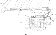
Figure 1 shows that one of embodiment of the present utility model, comprise brush 1, action bars 2 and supply tank 3, this supply tank 3 comprises casing 4, filler 5, has the water supply controlling organization of water inlet and delivery port.
As shown in Figure 1, brush 1 is connected the front end of action bars 2 by carriage 6 detachable (as screw thread).Axially run through being provided with feed pipe 7 in the action bars 2, the front end of feed pipe 7 also is provided with shower nozzle 7a, and this shower nozzle 7a is located on the brush 1.Action bars 2 and interior feed pipe 7 thereof are divided into two sections, also be provided with the extension bar 8 that feed pipe 7 is arranged between two sections and (also can add many as required, to obtain different use length), between action bars 2 and the extension bar 8 and between the extension bar 8 by 9 detachable connections of adapter sleeve, and fixing by fixation code 10, the feed pipe 7 in it is by the 11 detachable connections of water pipe connector.
As shown in Figure 1, the water supply controlling organization comprises air pump 12, valve switch 13 and water pipe 14, water pipe 14 is arranged in the casing 4, the one end places casing 4 bottoms as water inlet, the other end is connected on the valve switch 13, this valve switch 13 is arranged on casing 4 tops, and is connected to the rear end of feed pipes 7 in the action bars 2 by connection flexible pipe 15 as delivery port.
During work, need leave the volume space 1/4 or more so that hold gas during retaining in the casing 4, and cover tight filler 5, use air pump 12 pumps enough air in.The threshold switch 13 of fetching boiling water then, water by water pipe 14 and valve switch 13, are transported to feed pipe 7 in the action bars 2 through connecting flexible pipe 15 under strong gas pressure.Supply water to brush 1 by front end shower nozzle 8 then.In addition, also brush 1 and carriage 6 can be disassembled, action bars 2 is used as hydraulic giant.
For easy to carry, brush 1 and carriage 6, action bars 2 and extension bar 8 can be taken apart when not using.Simultaneously, roller 16 can be installed in the bottom of its casing 4 of supply tank, and anterior draw ring 17 and the stay cord 18 installed is with convenient carrying.
Embodiment two:
Fig. 2 and Figure 3 shows that two of embodiment of the present utility model, be with embodiment one difference: as shown in Figure 2, the casing 4 of supply tank is divided into retaining chamber 4a and control room 4b, the water supply controlling organization is arranged in the 4b of control room, comprise electric pump 19, attaching plug 20 and Water supply switch valve 21, the water inlet 19a of electric pump 19 is communicated with retaining chamber 4a, and its delivery port 19b is by connecting the rear end that flexible pipe 15 is communicated to feed pipe 7 in the action bars 2; Water supply switch valve 21 is arranged on the rear end of action bars 2, and connects control electric pump 19 by electric wire 22.4a top, retaining chamber is provided with passage 23 (this passage 23 also can be located on the lid 5a of filler) so that logical atmosphere is opened the lid 5a of filler 5 when perhaps using.At this moment, connect power supply after, open Water supply switch valve 21, electric pump 19 runnings, the rinse water in the casing then is transported to feed pipe 7 in the action bars 2 through connecting flexible pipe 15.This kind mode is applicable to convenient place of using supply socket such as family, office.In addition, attaching plug 20 also can adopt the form of automobile cigarette lighter, uses when cleaning automobile with convenience.
In addition, when some place is inconvenient to use supply socket, can adopt battery powered method, as shown in Figure 3, the water supply controlling organization also comprises battery 24 and charger 25, and electric pump 19 is electrically connected on the battery 24.
Embodiment three:
Figure 4 shows that three of embodiment of the present utility model, be with embodiment two differences: as shown in Figure 4, the retaining chamber 4a of supply tank also is provided with air pump 12, valve switch 13 and water pipe 14, water pipe 14 is arranged in the 4a of retaining chamber, the one end places retaining chamber 4a bottom as water inlet, the other end is connected on the valve switch 13, and this valve switch 13 is arranged on 4a top, retaining chamber, and is communicated with the flexible pipe 15 that is connected of electric pump delivery port 19b by connecting flexible pipe 26.
When needing to use air pressure to send water, its operation principle is with embodiment one.When need using electric pumps water, its operation principle is with embodiment two.
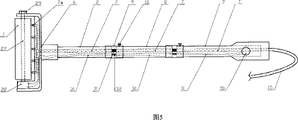
Embodiment four, five, six:
Fig. 5 and four and the embodiment that is respectively the utility model embodiment shown in Figure 6 five, six in brush and action bars.
Embodiment four, five, six is with embodiment one, two, three differences respectively: as shown in Figure 5 and Figure 6, brush 1 is arranged on the carriage 6 for cylinder type and by rotating shaft 27, and the shower nozzle 7a of feed pipe 7 front ends is arranged on the periphery of brush 1; Also be provided with brush head motor 28 on the carriage 6, an end of rotating shaft 27 is connected with the output shaft of brush head motor 28, and its other end is provided with clamp nut 29; The gauge tap 30 of brush head motor 28 is arranged on the rear end of action bars 2, and electric wire 31 is applied in the action bars 2.When opening the gauge tap 30 of brush head motor 28, brush 1 can drive automatic rolling by brush head motor 28 and scrub, and need not the user and promotes back and forth.In addition, also can close the gauge tap 30 of brush head motor 28 as required, clamp nut 29 is tightened, 1 of brush maintains static.
Claims (10)
1, a kind of automatic water jetting brushing and cleaning device comprises brush (1) and action bars (2), and described brush (1) is arranged on the front end of action bars (2); It is characterized in that: also comprise supply tank (3), this supply tank comprises casing (4), filler (5), has the water supply controlling organization of water inlet and delivery port; Axially run through in the described action bars (2) and be provided with feed pipe (7); The rear end of described feed pipe (7) is communicated with the delivery port of water supply controlling organization, and its front end arrives described brush (1).
2, automatic water jetting brushing and cleaning device according to claim 1, it is characterized in that: described water supply controlling organization comprises air pump (12), valve switch (13) and water pipe (14), described water pipe (14) is arranged in the casing (4), the one end places casing (4) bottom as water inlet, the other end is connected on the described valve switch (13), this valve switch is arranged on casing (4) top, and is connected to the rear end of the interior feed pipe of action bars (2) (7) as delivery port.
3, automatic water jetting brushing and cleaning device according to claim 1, it is characterized in that: the casing of described supply tank (4) is divided into retaining chamber (4a) and control room (4b), described water supply controlling organization is arranged in the control room (4b), comprise electric pump (19) and attaching plug (20), the water inlet of electric pump (19a) is communicated with retaining chamber (4a), and its delivery port (19b) is communicated to the rear end of the interior feed pipe of action bars (2) (7); Described action bars (2) is provided with the Water supply switch valve (21) that connects control electric pump (19); Top, described retaining chamber (4a) is provided with passage (23).
4, automatic water jetting brushing and cleaning device according to claim 3 is characterized in that: described water supply controlling organization also comprises battery (24) and charger (25), and described electric pump (19) is electrically connected on the battery (25).
5, according to claim 3 or 4 described automatic water jetting brushing and cleaning devices, it is characterized in that: described retaining chamber (4a) also is provided with air pump (12), valve switch (13) and water pipe (14), described water pipe (14) is arranged in the retaining chamber (4a), the one end places bottom, retaining chamber (4a) as water inlet, the other end is connected on the described valve switch (13), this valve switch (13) is arranged on top, retaining chamber (4a), and is connected to the rear end of the interior feed pipe of action bars (2) (7) as delivery port.
6, automatic water jetting brushing and cleaning device according to claim 1 is characterized in that: described brush (1) is arranged on the front end of action bars (2) by carriage (6), and this carriage (6) is detachable the connection with action bars (2); The front end of described feed pipe (7) also is provided with shower nozzle (7a).
7, automatic water jetting brushing and cleaning device according to claim 6 is characterized in that: the shower nozzle of described feed pipe front end (7a) is located on the brush (1).
8, automatic water jetting brushing and cleaning device according to claim 6 is characterized in that: described brush (1) also is arranged on the carriage (6) by rotating shaft (27) for cylinder type, and the shower nozzle of feed pipe front end (7a) is arranged on the periphery of brush (1); Also be provided with brush head motor (28) on the described carriage (6), an end of rotating shaft (27) is connected with brush head motor (28), and its other end is provided with clamp nut (29); The gauge tap (30) of described brush head motor (28) is arranged on the action bars (2), and electric wire (31) is applied in the action bars (2).
9, automatic water jetting brushing and cleaning device according to claim 1, it is characterized in that: described action bars (2) and interior feed pipe (7) thereof are divided into two sections, also be provided with one or the extension bar (8) of feed pipe (7) is arranged in one or more between two sections, by detachable connection of adapter sleeve (9), the feed pipe (7) in it is by the detachable connection of water pipe connector (11) between action bars (2) and the extension bar (8) and between the extension bar (8).
10, automatic water jetting brushing and cleaning device according to claim 8, it is characterized in that: described action bars (2) and interior feed pipe (7) and electric wire (31) thereof are divided into two sections, also be provided with one or feed pipe (7) is arranged and the extension bar (8) of electric wire (31) in one or more between two sections, by detachable connection of adapter sleeve (9), feed pipe (7) in it and electric wire (31) are respectively by water pipe connector (11) and detachable connection of electric wire connector (32) between action bars (2) and the extension bar (8) and between the extension bar (8).
Priority Applications (1)
| Application Number | Priority Date | Filing Date | Title |
|---|---|---|---|
| CNU2007200483248U CN201002086Y (en) | 2007-02-06 | 2007-02-06 | Automatic water-spraying bushing and washing device |
Applications Claiming Priority (1)
| Application Number | Priority Date | Filing Date | Title |
|---|---|---|---|
| CNU2007200483248U CN201002086Y (en) | 2007-02-06 | 2007-02-06 | Automatic water-spraying bushing and washing device |
Publications (1)
| Publication Number | Publication Date |
|---|---|
| CN201002086Y true CN201002086Y (en) | 2008-01-09 |
Family
ID=39037629
Family Applications (1)
| Application Number | Title | Priority Date | Filing Date |
|---|---|---|---|
| CNU2007200483248U Expired - Fee Related CN201002086Y (en) | 2007-02-06 | 2007-02-06 | Automatic water-spraying bushing and washing device |
Country Status (1)
| Country | Link |
|---|---|
| CN (1) | CN201002086Y (en) |
Cited By (4)
| Publication number | Priority date | Publication date | Assignee | Title |
|---|---|---|---|---|
| CN102513310A (en) * | 2011-11-30 | 2012-06-27 | 浙江工业大学 | Environment cleaning tool |
| CN105537156A (en) * | 2015-12-10 | 2016-05-04 | 河海大学常州校区 | Cleaning device for mirror of trough type solar concentrator |
| CN106491049A (en) * | 2016-11-28 | 2017-03-15 | 常州信息职业技术学院 | Clean electrical equipment |
| CN108392148A (en) * | 2017-02-08 | 2018-08-14 | 深圳市智意科技有限公司 | Cisten mechanism and intelligent sweeping |
-
2007
- 2007-02-06 CN CNU2007200483248U patent/CN201002086Y/en not_active Expired - Fee Related
Cited By (5)
| Publication number | Priority date | Publication date | Assignee | Title |
|---|---|---|---|---|
| CN102513310A (en) * | 2011-11-30 | 2012-06-27 | 浙江工业大学 | Environment cleaning tool |
| CN105537156A (en) * | 2015-12-10 | 2016-05-04 | 河海大学常州校区 | Cleaning device for mirror of trough type solar concentrator |
| CN106491049A (en) * | 2016-11-28 | 2017-03-15 | 常州信息职业技术学院 | Clean electrical equipment |
| CN106491049B (en) * | 2016-11-28 | 2018-11-27 | 常州信息职业技术学院 | Clean electric appliance |
| CN108392148A (en) * | 2017-02-08 | 2018-08-14 | 深圳市智意科技有限公司 | Cisten mechanism and intelligent sweeping |
Similar Documents
| Publication | Publication Date | Title |
|---|---|---|
| CN203805865U (en) | Car washer | |
| CN201002086Y (en) | Automatic water-spraying bushing and washing device | |
| CN205831417U (en) | Multifunctional domestic swab | |
| CN203943619U (en) | A kind of electronic glass cleaner | |
| CN201186645Y (en) | Environment-protective water-saving movable car washer | |
| CN210647375U (en) | Digit control machine tool belt cleaning device | |
| CN203472814U (en) | Multi-head rotary double-spraying-gun electric car brush | |
| CN211538712U (en) | DC cleaning machine | |
| CN103419758A (en) | Multi-head rotating double-spraying gun electric flow-through brush | |
| CN103989441A (en) | Electric glass wiper | |
| CN201913092U (en) | Multifunctional cleaning machine | |
| CN210506534U (en) | Plated item brushing device | |
| CN203256646U (en) | Power-driven cleaning tool for guardrail | |
| CN209186575U (en) | A kind of washroom cleaning device | |
| CN200960109Y (en) | Sand dishwasher | |
| CN219374565U (en) | Shoe brush | |
| CN204077624U (en) | A kind of water jet electric cleaner | |
| CN204998509U (en) | Handheld electronic multi -functional carwash ware | |
| CN202932302U (en) | Multifunctional dishware washing brush | |
| CN201511008U (en) | Water-saving multi-purpose cleaner | |
| CN214842738U (en) | Warm pipeline incrustation scale cleaning device that leads to | |
| CN203246445U (en) | Electric vehicle cleaning device | |
| CN213763106U (en) | High-pressure cleaning machine for machine tool | |
| CN2389519Y (en) | Auto-rotating multifunction water-saving cleaning brush | |
| CN201294971Y (en) | Spraying-rinsing brush |
Legal Events
| Date | Code | Title | Description |
|---|---|---|---|
| C14 | Grant of patent or utility model | ||
| GR01 | Patent grant | ||
| C17 | Cessation of patent right | ||
| CF01 | Termination of patent right due to non-payment of annual fee |
Granted publication date: 20080109 Termination date: 20100206 |