CN200961399Y - Limit support for opening window - Google Patents
Limit support for opening window Download PDFInfo
- Publication number
- CN200961399Y CN200961399Y CN 200620060793 CN200620060793U CN200961399Y CN 200961399 Y CN200961399 Y CN 200961399Y CN 200620060793 CN200620060793 CN 200620060793 CN 200620060793 U CN200620060793 U CN 200620060793U CN 200961399 Y CN200961399 Y CN 200961399Y
- Authority
- CN
- China
- Prior art keywords
- sheet
- kerve
- spacer
- bottom groove
- windowing
- Prior art date
- Legal status (The legal status is an assumption and is not a legal conclusion. Google has not performed a legal analysis and makes no representation as to the accuracy of the status listed.)
- Expired - Fee Related
Links
Images


Landscapes
- Window Of Vehicle (AREA)
Abstract
The utility model discloses a windowing limiting support used for horizontal windowing and suspending windowing, which comprises a suspending arm, a bottom groove, and a slipping device which is disposed in the bottom groove, wherein the slipping device is connected with one end of the suspending arm, and a supporting sheet is connected with the other end of the suspending arm, the slipping device comprises a slipping block which is installed in the bottom groove, a flexible sheet with one end provided on the slipping block and the other end fixedly connected with a locating sheet, and the locating sheet which is disposed in the inner portion of the bottom groove, and the top portion of the bottom groove is provided with a bayonet. When the slipping bock is moved to the position of the bayonet, the locating sheet is springed out of the bayonet and incapable of moving, and the suspending arm is stopped with a window being fixed, when the locating sheet is gently pressed, the flexible sheet together with the locating sheet is moved into the bottom groove and can be slipped again, when the limiting sheet is fastened, the limiting sheet receives forces from all directions, thereby the firmness is greatly improved, at the same time, all the operations can be realized only by gently pressing the limiting sheet, which are very convenient.
Description
Technical field
The utility model relates to a kind of stopping means that is used for casement window, outstanding window, particularly a kind of limited support of windowing.
Background technology
When window is opened, need be fixed with certain opening angle, reach the effect of daylighting and ventilation, existing a kind of limited support, comprise cantilever and kerve and be installed in the interior limited block of kerve, limited block is provided with lock screw, limited block and cantilever end are hinged, an other end of cantilever is hinged with supporting spring, supporting spring is fixed on the window, supporting spring rotated thereupon when window rotated, and the limited block of cantilever drive simultaneously slides in kerve, reaches the fixedly purpose of window by turn lock screw fixed limit piece.This device mainly is to stop moving of cantilever by the frictional force between lock screw and kerve, thereby fixing window, when wind-force excessive, the thrust that cantilever is subjected to is during greater than frictional force, still can drive limited block and slide, produce very big inertia simultaneously, window is closed suddenly, the broken glass of shake brings loss easily; Fixedly often need very big power just can screw lock screw during window in addition, use inconvenient.
Summary of the invention
In order to overcome the deficiencies in the prior art, the utility model provides a kind of good limit effect and the easy to operate limited support of windowing.
The technical scheme that its technical problem that solves the utility model adopts is: the limited support of windowing, comprise cantilever 1 and kerve 2, and be arranged on can be along its carriage that slides in the kerve 2, carriage and cantilever 1 end connection, an other client link of cantilever 1 has supporting spring 3, carriage comprises slide block 6, shell fragment 5 and spacer 7, slide block 6 is installed in the kerve 2, one end of shell fragment 5 is installed on the slide block 6, the other end is fixedlyed connected with spacer 7, spacer 7 is arranged on the inside of kerve 2, and kerve 2 tops are provided with some bayonet sockets 4 for spacer 7 ejections.
The beneficial effects of the utility model are: cantilever is embedded on the kerve by carriage, spacer was subjected to the effect of shell fragment and ejects bayonet socket when slide block moved to the bayonet socket position, and spacer is stuck in bayonet socket can't be continued to move, cantilever stop motion thereupon, window is fixed, press spacer gently, move up in the kerve under the shell fragment, slide once more, up to next bayonet socket, spacer ejects once more, and window is fixed once more, so repeatedly.Be subjected to the power of bayonet socket all directions when banking stop is stuck, firmness improves greatly, and simultaneously, whole operations only need be pressed banking stop gently and can be realized, and are quite simple.
Description of drawings
Below in conjunction with drawings and Examples the utility model is further specified.
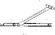
Fig. 1 is a structural representation of the present utility model;
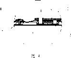
Fig. 2 is a front view of the present utility model;
Fig. 3 is a sectional view of the present utility model;
Fig. 4 is the partial enlarged drawing of Fig. 3.
The specific embodiment
Referring to figs. 1 through Fig. 4, the limited support of windowing, comprise cantilever 1 and kerve 2, and be arranged on can be along its carriage that slides in the kerve 2, carriage and cantilever 1 end connection, an other client link of cantilever 1 has supporting spring 3, carriage comprises slide block 6, shell fragment 5 and spacer 7, slide block 6 is installed in the kerve 2, one end of shell fragment 5 is installed on the slide block 6, the other end of shell fragment 5 is fixedlyed connected with spacer 7, and spacer 7 is arranged on the inside of kerve 2, and kerve 2 tops are provided with some bayonet sockets 4 for spacer 7 ejections.During actual the use, supporting spring 3 is fixed on the window page or leaf, kerve 2 is fixed on the window frame, and when window was closed, cantilever 1 overlaped with kerve 2, when opeing the window, cantilever 1 moves and drives carriage and slides on kerve 2 with window, when slide block 6 slided, spacer 7 moved in kerve 2 thereupon, shell fragment 5 is pressed down, when spacer 7 moves to bayonet socket 4, be subjected to the effect of shell fragment 5 and eject bayonet socket 4, spacer 7 is stuck in and can't continues on the bayonet socket 4 to move, cantilever 1 stop motion thereupon, window is fixed, and presses spacer 7 gently, with moving up under the shell fragment in the kerve 2, slide once more, up to next bayonet socket 4, spacer 7 ejects once more, when window is fixed once more, its opening angle also with regard to conversion the angle of a bit, changed the effect of daylighting and ventilation.
As further improvement of the utility model, the number of described bayonet socket 4 is 4, can live 4 different fixed angle after window is opened like this, and also can the reducing or increase of bayonet socket 4, the selection of the more angles of windowing of number also just many more more.
As further improvement of the utility model, described shell fragment 5 also is provided with button 8 with spacer 7 junctions, and button 8 is the major part rivet, and when pinning button 8, its smooth circular surface can increase the contact area with finger, and is user-friendly.Bottom, described in addition kerve 2 two ends is provided with limited block 9, skids off kerve 2 in the time of can avoiding slide block 6 sliding speeds too fast, brings unnecessary trouble.
Above-mentioned just the utility model preferred embodiment but should not constitute restriction of the present utility model, so long as adopt the technical scheme that is equal to the utility model also should be within the protection domain of the invention.
Claims (4)
1. the limited support of windowing, comprise cantilever (1) and kerve (2), and be arranged on can be along its carriage that slides in the kerve (2), carriage and cantilever (1) end connection, an other client link of cantilever (1) has supporting spring (3), it is characterized in that: carriage comprises slide block (6), shell fragment (5) and spacer (7), slide block (6) is installed in the kerve (2), one end of shell fragment (5) is installed on the slide block (6), the other end is fixedlyed connected with spacer (7), spacer (7) is arranged on the inside of kerve (2), and kerve (2) top is provided with some bayonet sockets (4) for spacer (7) ejection.
2. the limited support of windowing according to claim 1, the number that it is characterized in that described bayonet socket (4) is 4.
3. the limited support of windowing according to claim 1 is characterized in that described shell fragment (5) and spacer (7) junction also are provided with button (8).
4. the limited support of windowing according to claim 1 is characterized in that two ends, described kerve (2) bottom are provided with limited block (9).
Priority Applications (1)
| Application Number | Priority Date | Filing Date | Title |
|---|---|---|---|
| CN 200620060793 CN200961399Y (en) | 2006-06-21 | 2006-06-21 | Limit support for opening window |
Applications Claiming Priority (1)
| Application Number | Priority Date | Filing Date | Title |
|---|---|---|---|
| CN 200620060793 CN200961399Y (en) | 2006-06-21 | 2006-06-21 | Limit support for opening window |
Publications (1)
| Publication Number | Publication Date |
|---|---|
| CN200961399Y true CN200961399Y (en) | 2007-10-17 |
Family
ID=38797909
Family Applications (1)
| Application Number | Title | Priority Date | Filing Date |
|---|---|---|---|
| CN 200620060793 Expired - Fee Related CN200961399Y (en) | 2006-06-21 | 2006-06-21 | Limit support for opening window |
Country Status (1)
| Country | Link |
|---|---|
| CN (1) | CN200961399Y (en) |
Cited By (3)
| Publication number | Priority date | Publication date | Assignee | Title |
|---|---|---|---|---|
| CN103015822A (en) * | 2011-09-26 | 2013-04-03 | 松下电气机器(北京)有限公司 | Opening angle retention mechanism of emergency door of subway shielded door |
| CN103847471A (en) * | 2014-04-03 | 2014-06-11 | 江苏畅通车业发展有限公司 | Passenger car emergency escaping window with mechanical type rod supporting mechanism |
| CN110700709A (en) * | 2019-11-20 | 2020-01-17 | 湖南展冠建材有限责任公司 | Adjustable transmission device of casement window |
-
2006
- 2006-06-21 CN CN 200620060793 patent/CN200961399Y/en not_active Expired - Fee Related
Cited By (3)
| Publication number | Priority date | Publication date | Assignee | Title |
|---|---|---|---|---|
| CN103015822A (en) * | 2011-09-26 | 2013-04-03 | 松下电气机器(北京)有限公司 | Opening angle retention mechanism of emergency door of subway shielded door |
| CN103847471A (en) * | 2014-04-03 | 2014-06-11 | 江苏畅通车业发展有限公司 | Passenger car emergency escaping window with mechanical type rod supporting mechanism |
| CN110700709A (en) * | 2019-11-20 | 2020-01-17 | 湖南展冠建材有限责任公司 | Adjustable transmission device of casement window |
Similar Documents
| Publication | Publication Date | Title |
|---|---|---|
| CN2923936Y (en) | Window-opening limit-strut | |
| CN200961399Y (en) | Limit support for opening window | |
| CN209995770U (en) | display device with transparent display screen | |
| CN102025071A (en) | Hidden socket for digital portable equipment | |
| CN212317764U (en) | Sliding door with buffering function | |
| CN212656693U (en) | Small-size window opens stop device | |
| CN201781714U (en) | Slide portable information terminal | |
| CN201511789U (en) | Transmission mechanism for automobile skylight opening | |
| CN213211351U (en) | Forced control type AI intelligent learning terminal | |
| CN211280741U (en) | Automobile armrest with cup holder | |
| CN209312930U (en) | Automatic assembly line terminal assembling device | |
| CN201887249U (en) | Hidden socket of digital portable equipment | |
| CN213477952U (en) | Door and window limiting device | |
| CN209932014U (en) | Drawer guide rail pressing rebounding device | |
| CN213391692U (en) | Folding lifting window convenient to open and close | |
| CN110783746A (en) | Connector device with protective door | |
| CN221220245U (en) | Stainless steel door with sealing structure | |
| CN217631764U (en) | Refrigerator door helping hand handle | |
| CN112286306B (en) | Fixing auxiliary mechanism for computer USB socket capable of avoiding poor contact | |
| CN221307645U (en) | Novel wine cabinet with multiple temperature areas | |
| CN208875892U (en) | A kind of wooden screen of portable home decoration that stability is strong | |
| CN211441742U (en) | Drawing instrument convenient for drawing | |
| CN214945487U (en) | Clamping device and electronic product clamping support with same | |
| CN217973607U (en) | High-efficient pocket machine of opening | |
| CN216220649U (en) | Art design table |
Legal Events
| Date | Code | Title | Description |
|---|---|---|---|
| C14 | Grant of patent or utility model | ||
| GR01 | Patent grant | ||
| C17 | Cessation of patent right | ||
| CF01 | Termination of patent right due to non-payment of annual fee |
Granted publication date: 20071017 |