CN1964830A - Simplified in-mold article handling system and method for handling molded articles - Google Patents
Simplified in-mold article handling system and method for handling molded articles Download PDFInfo
- Publication number
- CN1964830A CN1964830A CNA2004800367640A CN200480036764A CN1964830A CN 1964830 A CN1964830 A CN 1964830A CN A2004800367640 A CNA2004800367640 A CN A2004800367640A CN 200480036764 A CN200480036764 A CN 200480036764A CN 1964830 A CN1964830 A CN 1964830A
- Authority
- CN
- China
- Prior art keywords
- slide
- handling system
- assembly
- article handling
- mold
- Prior art date
- Legal status (The legal status is an assumption and is not a legal conclusion. Google has not performed a legal analysis and makes no representation as to the accuracy of the status listed.)
- Pending
Links
Images


Classifications
-
- B—PERFORMING OPERATIONS; TRANSPORTING
- B29—WORKING OF PLASTICS; WORKING OF SUBSTANCES IN A PLASTIC STATE IN GENERAL
- B29C—SHAPING OR JOINING OF PLASTICS; SHAPING OF MATERIAL IN A PLASTIC STATE, NOT OTHERWISE PROVIDED FOR; AFTER-TREATMENT OF THE SHAPED PRODUCTS, e.g. REPAIRING
- B29C45/00—Injection moulding, i.e. forcing the required volume of moulding material through a nozzle into a closed mould; Apparatus therefor
- B29C45/17—Component parts, details or accessories; Auxiliary operations
- B29C45/1769—Handling of moulded articles or runners, e.g. sorting, stacking, grinding of runners
-
- B—PERFORMING OPERATIONS; TRANSPORTING
- B29—WORKING OF PLASTICS; WORKING OF SUBSTANCES IN A PLASTIC STATE IN GENERAL
- B29C—SHAPING OR JOINING OF PLASTICS; SHAPING OF MATERIAL IN A PLASTIC STATE, NOT OTHERWISE PROVIDED FOR; AFTER-TREATMENT OF THE SHAPED PRODUCTS, e.g. REPAIRING
- B29C45/00—Injection moulding, i.e. forcing the required volume of moulding material through a nozzle into a closed mould; Apparatus therefor
- B29C45/17—Component parts, details or accessories; Auxiliary operations
- B29C45/40—Removing or ejecting moulded articles
- B29C45/42—Removing or ejecting moulded articles using means movable from outside the mould between mould parts, e.g. robots
- B29C45/4225—Take-off members or carriers for the moulded articles, e.g. grippers
-
- B—PERFORMING OPERATIONS; TRANSPORTING
- B29—WORKING OF PLASTICS; WORKING OF SUBSTANCES IN A PLASTIC STATE IN GENERAL
- B29L—INDEXING SCHEME ASSOCIATED WITH SUBCLASS B29C, RELATING TO PARTICULAR ARTICLES
- B29L2031/00—Other particular articles
- B29L2031/56—Stoppers or lids for bottles, jars, or the like, e.g. closures
- B29L2031/565—Stoppers or lids for bottles, jars, or the like, e.g. closures for containers
Abstract
An in-mold lid handling system provides a slide that is operable to translate laterally across a molding face of an injection mold to perform a first operation on, or to retrieve a plurality of molded articles from, a column of molding cavities and to thereafter retreat to an outboard position for a second operation, or to transfer the molded articles to drop chutes. The driving means for the slide including a first and a second transmission attached to the ends thereof. The transmissions operate on the same basic principle wherein at least one belt contained therein is configured along a path defined by a plurality of guides, the path including a plurality of segments defined between the guides, and the at least one belt being operable along the path between two positions, wherein the slide is attached to various suitably arranged path segments and is thereby driven between the inboard and the outboard positions respectively.
Description
Technical field
The present invention relates generally to a kind of in-mold article handling system of simplification, and more properly but do not say exclusively, the present invention relates to treatment system in a kind of mould, it comprises the transmission device of simplification, molded that is used to cross injection molding drives slide between inner side and outer fix, to handle the article of described injection molding respectively between the molded hole of the article (for example lid) of injection molding and drop chute.
Background technology
For example when incorporating the injection molding system that is used for the production container cover into, the advantage that is provided by in-mold article handling system according to the present invention becomes obvious.And, hereinafter will under the background of injection molding cover mold system system, describe treatment system in the mould of the present invention therefore, in that the general utility of treatment system is not implied under the situation of any this type of restriction.
Referring to Fig. 1, show a cover mold system system among the figure, it comprises injection molding machine clamping unit 34, described injection molding machine clamping unit 34 is equipped with four layers of lid stack mold 36 between stationary platen 50 and moving press plate 52.Injection molding machine, clamping unit 34 and mould 36 can be operated as usually known.As described substantially among the United States Patent (USP) Re 37,827, clamping unit further is shown as and comprises clamping sub-assembly 54, is used for operation injection molding 36 between the configuration of opening, closing and clamping.Injection molding 36 disposes, and therefore comprises mould inner cap treatment system 59 for high power capacity, effective lid production.For the supporting process of carrying, piling up and encapsulate for for example lid simple integrated, described mould inner cap treatment system 59 is integrated in the injection molding process, is used for distinguishing containment cap (not shown) and also will covers from injection molding and transfer to a succession of drop chute.
As shown in fig. 1, described supporting process can comprise four lid conveyer passages 91,92,93,94, each lid conveyer passage is exclusively used in is a pair of drop chute 77 services, described drop chute 77 is provided be each molded 81,82,83,84 services.Each lid conveyer passage 91,92,93,94 be positioned at injection molding machine clamping unit 34 below, in the mould closed position, to aim at and engagement with corresponding drop chute 77.Lid (not shown) can be transferred to the lid pack platform 80 that is positioned at behind the injection molding machine clamping unit 34 with bonnet conveyer 91,92,93 and 94.
Described lid pack platform can comprise a succession of rotating bars lid stacker 96, be used for lid (not shown) is piled up, wherein each rotating bars covers the corresponding lid conveyer passage 91,92,93,94 of stacker, subsequently, lid 14 through piling up is transported to sack filling machine 98 by transfer mechanism 97, it will pile up 16 packs through the lid of encapsulation and it will be discharged on the conveyer 99, be used for handling box downwards.
Say that in further detail injection molding 36 comprises four molded 81,82,83,84, wherein each includes the parallel row in a pair of molded hole.Each molded 81,82,83,84 all is provided between core board sub-assembly 60,61 and the complementary cavity plate sub-assembly 63.Show cavity plate assemblies 63 in more detail referring to Fig. 2. Core board sub-assembly 60,61 is provided by centronucleus core sub-assembly 61 and two single mode system face core board sub-assemblies 60 being installed in respectively on stationary platen and the moving press plate.Contiguous molded 81,82, the face of 83 and 84 core board sub-assembly 60,61 comprise core molded insert 65, and it provides the part in molded hole.Contiguous molded 81,82,83 and 84 cavity plate assemblies 63 comprise hole molded insert 67, and its complementary portion with molded hole is provided to the part of core molded insert 65.Core and cavity plate assemblies are shown as through arranging so that a pair of cavity plate assemblies 63 (after this being called first and second cavity plate assemblies 63) is provided between every pair of center core board sub-assembly 61 and the core board sub-assembly 60.First and second cavity plate assemblies 63 are installed on the either side of shared hot flow path 62.Each hot flow path 62 (wherein having two is in four layers of mould) comprises sprue bar 58 as shown in Figure 2, is used for hot flow path 62 is coupled to the injection unit (not shown) that is used to support moulding material stream as is generally known.For the purpose of reference, first and second cavity plate assemblies 63 and their hot flow path 62 can be generically and collectively referred to as mold hot section 37.
Serve by mould inner cap treatment system 59 for each molded.And referring to Fig. 1, each mold hot section 37 includes the part of the mould inner cap treatment system 59 that is attached to its hot runner assembly 62 therefore.Mould inner cap treatment system 59 comprises contiguous each molded 81,82,83, the slide 70 of 84 a pair of vertical orientation, described slide can be operated crossing transverse translation herein, to regain a plurality of lids (not shown) and subsequently described lid (not shown) to be sent to drop chute 77 from the vertical row of the core molded insert 65 of correspondence.As shown in Figure 2, each slide 70 is driven and is guided by dedicated transmission that is installed to hot flow path 62 and servo motor 72.Slide 70 is generally the light weight rigid track of being made by plastics or aluminium, and it has and is installed to its face to be used for engages cap 12 for a plurality of molded articles holding devices that transmit, and for example sucker 71.Each slide 70 all can further comprise vacuum channel (not shown), is used for sucker 71 is connected to controlled vacuum (not shown), and described vacuum source provides a member so that controllably will cover and sucker 71 coupling and decouplings.
Mentioned as mentioned, mould inner cap treatment system 59 also comprises a pair of drop chute 77 of contiguous each cavity plate assemblies 63.Referring to Fig. 1, show that every pair of drop chute 77 all is installed to the corresponding outside of hot flow path 62 and is positioned on the either side on the cavity plate assemblies 63 and adjacent hole plate sub-assembly 63 usually with vertical substantially orientation.Referring to Fig. 5, show typical drop chute 77 among the figure.Drop chute 77 is elongated " U " shape raceway groove, and its open end is to the lateral edges of lid 12 (not shown), and lid 12 is retained on the slide 70, makes when lid moves to outer fix, and lid enters in the openend of drop chute raceway groove, as shown in Figure 7.Drop chute 77 comprises that further guide slits 86 thinks that the sucker 71 of slide 70 provides the gap, makes that cover 12 can be positioned in the drop chute 77 before sucker 71 releases substantially fully.
Referring to Fig. 2, show among the figure that mould inner cap treatment system 59 is installed on the mold hot section, be used to molded 82 service, shown in direction 2-2 among Fig. 1 goes up, wherein each slide 70 is connected to the one side of hot flow path 62 slidably by dedicated transmission (that is, driving shaft 73, driven wheel 75, rack/linear rails 76 and wire bearing 74) and servo motor 72.Therefore, each slide 70 comprises the rack/linear rails 76 that is fastened to its end, and described rack/linear rails 76 is with respect to slide 70 and orientation, with support slide 70 usually perpendicular to its longitudinal axis transverse translation.Rack/linear rails itself is placed in the wire bearing 74, and wire bearing 74 is attached to the front of hot flow path 62.The rotating driveshaft 73 of the driven wheel 75 that comprises a pair of section of rack that is used for pinion rack/linear rail is provided, is used to drive each slide 70.In use, driving shaft is by dedicated servo motor 72 rotations.The detailed construction and the operation of this type of in-mold molded article-handling system are provided in the U.S. patent application case 10/287,809 simultaneously co-pending.Certainly, also can use to substitute mould inner cap treatment system, for example United States Patent (USP) 5,518, the swinging chute described in 387.
In operation, the steps that lid 12 is regained and shifted from mould 36 comprise: slide 70 located lateral in inner side (shown in the reference symbol A Fig. 2), are made sucker 71 be positioned to be immobilizated in before the front of exposure of a plurality of lids 12 on the core molded insert 65 (not shown); A plurality of lids 12 are discharged to from core molded insert 65 on corresponding a plurality of suckers 71, and described discharging operation is provided by a plurality of mold releasability device rings 65 (not shown) that are provided on the core board sub-assembly; In outer fix (shown in the reference symbol B among Fig. 2), wherein fixing lid thereon is positioned in the drop chute 77 (not shown) with slide 70 located lateral; Subsequently, for example will cover 12 from sucker 72 releases to blow through sucker 71, and move down in the raceway groove in drop chute under the influence of gravity, to be discharged in the supporting process subsequently with bonnet 12 by the counter-rotating vacuum source.
Though treatment system 59 has successfully been improved the efficient and the flexibility of cover mold system system in the known before this mould, but still there are the cost of this type of treatment system of reduction and the difficult problem of complexity.In addition, much configuration of the structure of treatment system and layout have been brought undesirable or unnecessary complexity and limitation in this type of mould for himself, wherein can comprise: with mould relevant complexity is installed; With with molded hole spacing and maximum mold cavitation (that is the number in the molded hole on molded) relative restrictions.
Particularly, be stored in dedicated servo motor 72 must be provided and drive a lot of expenses that each slide 70 is associated.Therefore, referring to Fig. 1, four layers of stack mold that have its four molded 81,82,83 and 84 and two capable molded hole and therefore be positioned at the slide 70 on each molded require 8 servo motors 72.In addition, as shown in Figure 2, the wire bearing 74 and the linear rail 76 that are used for mould inner cap treatment system mentioned above are generally expensive high precision components.When a large amount of this class component of needs, (for example need under the situation of four layers of stack mold among Fig. 1 of 16 groups of wire bearings 74 and linear rail 76) foregoing problems particularly important therein.In addition, rack/linear rails 76 is made by metal (for example aluminium and steel) quite greatly and usually, and therefore can have the considerable momentum (being high moving mass) of slide 70 round two-forty between inboard and outer fix, and this may restriction system performance.
Once more referring to Fig. 2, between hope vertically is installed in injection molding 36 connecting rod 56 of clamping unit 34 when (this is common installation exercise), will take place and the complexity that injection molding 36 is installed in the injection molding machine clamping unit 34, and wherein waling stripe 56 gaps are greater than the width of injection molding 36, but others are less than the width of injection molding 36, described others comprise mould inner cap treatment system 59 mounted thereto, as calculating according to the outwards outermost extent of outstanding tooth bar linear rail 76 in the outer fix.Under these circumstances, between the mould installation period, the rack/linear rails 76 in the outer fix can be disturbed connecting rod 56.Therefore, the installation of the injection molding 36 under this type of situation can require the interior part treatment system 59 of mould to remove at least in part from injection molding 36, maybe can specify injection molding 36 is installed in its littler part, makes slide 70 to be parked in the inner side.Must employ the angle that the technical professional carefully removed and reinstalled mould inner cap treatment system 59 from the mould set-up time that increases, production loss and possibility therefore, this generic request causes sizable cost.Therefore, do not wish to obtain laterally projecting part and in the mould closed position, extend to mould inner cap treatment system outside the sealing of injection molding 36.
Referring to Fig. 2, transmission device (that is, wire bearing 74 and linear rail) the desired placement and the space that hold mould inner cap treatment system 59 may form remarkable restriction to the hole spacing and the maximum mold cavitation of injection molding 36 once more.For instance, the vertical placement of linear rail 76 is arranged by connecting rod 56, makes describedly when linear rail 76 is positioned in the outer fix not have interference between the two.Therefore, place molded hole can with vertical space be restricted thus.
Therefore, need provide a kind of simplifies and relatively cheap interior treatment system of the mould that is used for molded articles.In addition, need treatment system 59 in a kind of mould, it can not make the process that injection molding 36 is installed in the folder machine clamping unit 34 become complicated, and it is relative with maximum mold cavitation relative restrictions minimum with molded hole spacing.
Summary of the invention
According to a first aspect of the invention, provide a kind of in-mold article handling system, it is configured for use in and is installed to first mould sections.Described first mould sections comprises at least one the plate sub-assembly that is provided on its first side.Described at least one plate sub-assembly comprises that at least one is arranged on the molded hole part with the opening that passes its front and dispose wherein.Described in-mold article handling system comprises: at least one slide, and it is provided by elongated track, in use disposes a plurality of article holding devices on the front of described elongated track, is used to mesh article for transmission; First and second transmission devices, it is typically connected to the place, opposite end of described at least one slide, in use described transmission device cooperation described at least one slide of front translation between inner side and outer fix to cross at least one plate sub-assembly, the described inner side that wherein moves to contiguous described at least one molded hole part to be carrying out first operation, and moves to the described outer fix that is spaced laterally apart previously from least one plate sub-assembly to carry out second operation; Dynamic component is used to drive first and second transmission devices.In first and second transmission devices each includes: frame plate; Be included in wherein flexibly connect member along at least one of a path configurations; Be installed to the plurality of guides of the end face of the frame plate that defines described path; The path that comprises a plurality of route segments that defined between the described guide rail; Driver part, it flexibly connects the member coupling with dynamic component and at least one, for use in use along the path operations between first and second position described both.Wherein at least one slide is attached at least one along one in the route segment that will drive with it and flexibly connects member, and like this, in use, when described at least one when flexibly connecting the path operations of member between first and second position, described at least one slide is operated between inboard and outer fix respectively accordingly.
According to a second aspect of the invention, provide a kind of injection molding, it comprises at least one in-mold article handling system that is installed to its at least one mould sections.Described at least one mould sections comprises at least one the plate sub-assembly that is provided on its first side.Described at least one plate sub-assembly comprises that at least one is arranged on the molded hole part with the opening that passes its front and dispose wherein.Described in-mold article handling system comprises: at least one slide, and it is provided by elongated track, in use disposes a plurality of article holding devices on the front of described elongated track, is used to mesh article for transmission; First and second transmission devices, it is typically connected to the place, opposite end of described at least one slide, in use described transmission device cooperation described at least one slide of front translation between inner side and outer fix to cross at least one plate sub-assembly, the described inner side that wherein moves to contiguous described at least one molded hole part to be carrying out first operation, and moves to the described outer fix that is spaced laterally apart previously from least one plate sub-assembly to carry out second operation; Dynamic component is used to drive first and second transmission devices, and each in first and second transmission devices includes: frame plate; Be included in wherein flexibly connect member along at least one of a path configurations; Be installed to the plurality of guides of the end face of the frame plate that defines described path; The path that comprises a plurality of route segments that defined between the described guide rail; Driver part, it flexibly connects the member coupling with dynamic component and at least one, for use in use along the path operations between first and second position described both.Wherein at least one slide is attached at least one along one in the route segment that will drive with it and flexibly connects member, and like this, in use, when at least one flexibly connected the path operations of member between first and second position, at least one slide was operated between inboard and outer fix respectively accordingly.
According to a third aspect of the invention we, provide a kind of for the transmission device that in in-mold article handling system, uses.Described in-mold article handling system is configured for use in first mould sections that is installed to mould.Described first mould sections comprises at least one the plate sub-assembly that is provided on its first side.Described at least one plate sub-assembly comprises that at least one is arranged on the molded hole part with the opening that passes its front and dispose wherein.Described transmission device comprises: frame plate; Be included in wherein flexibly connect member along at least one of a path configurations; Be installed to the plurality of guides of the end face of the frame plate that defines described path; Comprise the path that is defined in a plurality of route segments between the described guide rail; Driver part, it in use is coupled to dynamic component and at least one flexibly connects member, with in use be used for along the path operations between first and second position described both.Wherein transmission device is configured in use make at least one slide to be attached at least one along one in the route segment that will drive with it and flexibly connects member, and thus, when at least one flexibly connected the path operations of member between first and second position, at least one slide was operated between inboard and outer fix respectively accordingly.
According to a further aspect in the invention, providing a kind of is used for by using in-mold article handling system to handle the method through molded article from mould.Described in-mold article handling system is configured to cross at least one molded at least one slide that comes to have above the translation at least one article holding device of mould, and described in-mold article treating apparatus further comprises at least one drop chute.Said method comprising the steps of:
I) cross molded with at least one slide located lateral in inner side, make described at least one article holding device before one of molded article expose the front, regain article to be used for being immobilizated in a plurality of on the core molded insert through the location;
Ii) be discharged to from the core molded insert on corresponding a plurality of suckers through molded article a plurality of;
Iii) drop chute is navigated in the retracted position, be used to take in be retained on the slide sucker through molded article;
Iv) with the slide located lateral in outer fix, wherein the fixing article through molded thereon are positioned in the drop chute;
V) when through molded article when their sucker discharges, drop chute is moved forward in the front position, and with after molded article moving down in the raceway groove in drop chute under the influence of gravity, to be discharged in the supporting process subsequently.
Description of drawings
With reference to accompanying drawing one exemplary embodiment of the present invention is described, wherein:
Fig. 1 is the plane that comprises the typical cover mold system system of four layers of stack mold with mould inner cap treatment system;
Fig. 2 is the front view that the mold hot section 37 of known mould inner cap treatment system is installed on it, and described figure obtains along the section line 2-2 shown in Fig. 1;
Fig. 3 A and 3B are perspective views, show that the difference of described figure is that the two shows that respectively slide is positioned at inboard and outer fix according to the top and the sidepiece of the injection molding hot arc 37 that comprises mould inner cap treatment system of first embodiment of the invention;
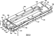
Fig. 3 C is a perspective view, the bottom of the injection molding hot arc 37 of exploded view 3B and sidepiece and mould inner cap treatment system;
Fig. 4 A is a perspective view, shows top and sidepiece according to the injection molding hot arc 37 that comprises mould inner cap treatment system of second embodiment of the invention, and it shows that slide is positioned at inner side;
Fig. 4 B is a perspective view, the bottom of the injection molding hot arc 37 of exploded view 4A and sidepiece and mould inner cap treatment system;
Fig. 5 is a perspective view, shows top and sidepiece according to the mould inner cap treatment system of the present invention of Fig. 3 A, 3B and 3C, and described mould inner cap treatment system further is equipped with the distortion upper frame plate with band tension piece and has the drop chute of a piston assembly;
Fig. 6 A is a perspective view, shows the upper frame plate according to the mould inner cap treatment system of Fig. 5;
Fig. 6 B is the perspective view according to the last transmission device of the mould inner cap treatment system of Fig. 5;
Fig. 7 is the plane of mould inner cap treatment system according to a preferred embodiment of the invention.
The specific embodiment
Show and various embodiment according to mould inner cap treatment system 59 of the present invention hereinafter are described in further detail referring to Fig. 3 A, 3B, 3C, 4A, 4B, 5,6A, 6B and 7.Although be understood by those skilled in the art that, mould inner cap treatment system 59 can be configured for use in and be installed on the core board sub-assembly 60,61, or with only having 36 uses of single molded typical injection molding, but as shown in Fig. 3 A, 3B, 3C, 4A and 4B, each among these embodiment of mould inner cap treatment system 59 all is shown as and is configured to be installed on the mold hot flow 62 of injection molding hot arc 37.In addition, although be understood by those skilled in the art that, the number of the row in molded hole have change and therefore the quantity of slide 70 have variation, but for the purpose of clear and continuity, the configuration of injection molding 36 will be described with preamble and as shown in fig. 1 identical, and therefore slide 70 layouts of mould inner cap treatment system 59 will be described with preamble and as shown in fig. 1 identical.Therefore, mould inner cap treatment system 59 molded hole (not shown) service that provides the slide 70 of a pair of vertical orientation to think to be positioned at the parallel columns on each molded 81,82,83 and 84.And mould inner cap treatment system described as preamble and as shown in Figure 2, can operate slide 70 to cross molded 81,82,83 and 84 laterally translations, regaining a plurality of lids 12, and will cover 12 subsequently and be sent to drop chute 77 from the core molded insert 65 (not shown) of respective column.Except that the end of slide 70 by its be coupled to respectively upper and lower transmission device 100 and 100 ', 200 and 200 ' or 300 and 300 ' member, the structure of slide 70 is constant basically.
Transmission device 100,100 ', 200,200 ', 300 and 300 ' various embodiment all with the operation of identical basic principle, at least one that wherein is contained in the described transmission device is with 101,202,204 and 301 along the path configurations that is defined by plurality of guides, described path is included in a plurality of sections that define between the described guide rail, and can wherein be connected to each route segment that suitably disposes 102 and 104 along described at least one band of the path operations between two positions, therefore 202 and 204 and 302 and 304 slide 70 is driven between inboard and outer fix respectively.
Last transmission device 100,200 or 300 and underdrive device 100 ', 200 ' or 300 ' be configured for use in the end face and the bottom surface that are respectively installed to hot flow path 62 sub-assemblies.As referring to shown in Figure 5, upper and lower transmission device is connected by common drive shaft 73, and driving shaft 73 is driven by servo motor 72.Driving shaft 73 further comprises a pair of driven wheel 110, first driven wheel is positioned in transmission device 100,200 or 300 and is used for it is driven, second driven wheel is positioned at an end place of driving shaft 73, be used to drive underdrive device 100 ', 200 ' or 300 '.Up and down transmission device 100 and 100 ', 200 and 200 ' and 300 and 300 ' between mechanical arrangements and layout substantially the same.Up and down transmission device 100 and 100 ', 200 and 200 ' and 300 and 300 ' between simple change can be and exist or do not exist the center die service of passing it and extending to insert otch 170.Inserting otch 170 allows near the mold services joint face 88 on the end face that is positioned at hot flow path 62, provide mold services (promptly so that will be used to, electric, empty G﹠W) various connectors and manifold (not shown) be installed to hot flow path 62 and cavity plate assemblies 63 both, and/or be installed to be used for attached as thing of mould pin (moldfeet) and so on or the similar joint face (not shown) on the bottom of the hot flow path 62 that connects of multi-mould service more.For the purpose that presents, last transmission device 100,200 and 300 comprises otch 170, and underdrive device 100 ', 200 ' or 300 ' do not comprise.Upper and lower transmission device 100 and 100 ', 200 and 200 ' or 300 and 300 ' in each be based upon respectively on upper and lower frame plate 130 and 131,230 and 231 and 330 and 331, equally, the only variant upper frame plate 130,230 and 330 that is between the frame plate of up and down comprises that the center die service inserts otch 170, and lower frame frame plate 131,231,331 does not comprise.Do not show among Fig. 3 A, 3B and the 4A lower frame frame plate 131 ' and 231 ', so that underdrive device 100 ' and 200 ' transmission component clearly as seen.Similarly, do not show upper frame plate 130 and 230 among Fig. 3 C and the 4B, so that the transmission component of last transmission device 100 and 200 clearly as seen.
By transmission device 100,100 ', 200,200 ', 300 and 300 ' various embodiment in each favourable aspect that provides be, they make the lid treatment system 59 of the present invention can be simpler and more cheap, avoid the complexity and the limitation of previously described mould inner cap treatment system simultaneously.Particularly, transmission device 100,100 ', 200,200 ', 300 and 300 ' various embodiment in do not have one to require to use linear rail 76 or wire bearing 74 with its intrinsic expense, space requirement and high moving mass.Transmission device 100,100 ', 200,200 ', 300 and 300 ' all slides 70 of make using single servo motor 72 drive the lid treatment system 59 that is connected to each mold hot section 37 become possibility.In addition, transmission device 100,100 ', 200,200 ', 300 and 300 ' all end face and the bottom surfaces that are designed to secure to simply mold hot section 37, make the front of cavity plate assemblies 63 free relatively, with optimization mould hole layout and service is provided.In addition, transmission device 100,100 ', 200,200 ', 300 and 300 ' assembly all be contained in fully wherein, so that in its operating period, do not have one outwards laterally projectingly in the assembly, and therefore do not exist and the possibility that connecting rod 56 disturbs or any additional complexity of installing with respect to injection molding 36.
Structure and the operation of the various embodiment of mould inner cap treatment system 59 now are described in further detail.For the purpose of efficient, as mentioned before, whenever the structure of the various embodiment that provide transmission device 100,200,300 and the description of operation, just be interpreted as corresponding underdrive device 100 ', 200 ', 300 ' structure be operating as identical, except requirement to mold services otch 170.
According to first embodiment of part treatment system 59 in the mould, as shown in Fig. 3 A, 3B and 3C, treatment system 59 comprise upper and lower transmission device 100,100 '.Each transmission device 100,100 ' comprise rotating band 101, it is along the paths arrangement that comprises four functional path segments 102,104,106 and 108.Particularly, route segment 102, rear path segment 104, driving route segment 106 and return path section 108 before functional path segments comprises.
The a pair of slide 70 that is close to each cavity plate assemblies 63 and is provided with must be configured to cross front translation between inner side and outer fix on relative mutually direction of cavity plate assemblies 63.That is, slide 70 focuses on inner side towards mold center's line, cover 12 to regain, and slide 70 diverges to outer fix subsequently, is aligned in the drop chute 77 will cover 12.Therefore, before every internal slide 70 is attached to respectively and rear path segment 102,104, precedingly be configured on relative substantially direction, operate with rear path segment 102,104.
Therefore, provide before and rear path segment 102,104 drive contiguous mold hot section 37 first cavity plate assemblies 63 the front and locate described to slide 70.The front of preceding route segment 102 contiguous first cavity plate assemblies 63, outside first and second, provide along its shared first longitudinal edge between the idle pulley 112,114, the wherein said first and second outer idle pulleys 112,114 are positioned at the outermost corner of frame plate 130, and route segment 102 is parallel to the front of first cavity plate assemblies 63 and closely separates from it wherein, make be attached to before the slide 70 of route segment 102 can cross the face of first cavity plate assemblies 63 and translation freely.
Similarly, before rear path segment 104 is arranged in behind the route segment 102, idle pulley 104 and outside second closely near idle pulley 112 outside first and outside first between the idle pulley 116 of the inside slightly staggered back of idle pulley 112, route segment 102 before making rear path segment 104 be parallel to and arrange and separate from it with the distance of the diameter that equals the second outer idle pulley 114 is wherein with half of the circumference of 101 windings, the second outer idle pulley 114.So, rear path segment 104 also should be parallel to the front of first cavity plate assemblies 63 and still closely separate with it, also can cross the face of cavity plate assemblies 63 and translation freely so that be attached to the slide 70 of rear path segment 104.
Before with the span of rear path segment 102,104, and therefore first outer idle pulley 112, the second outer idle pulley 114 and after the position of idle pulley 116 must be enough to allow to be attached to its slide 70 complete translation between inboard and outer fix.
Similarly, with rear path segment 102,104, that locatees with the front of second cavity plate assemblies 63 on the opposite side that drives contiguous mold hot section 37 is described to slide 70 before also providing.Therefore, preceding and rear path segment 102,104 is close to the front of second cavity plate assemblies 63, arranging along its shared second longitudinal edge between idle pulley 112,114 and the back idle pulley 116 outside first and second in a similar fashion, is the outermost corner that described idle pulley is positioned at frame plate 130.
Return path section 108 extension between the first outer idle pulley 112 of contiguous first and second cavity plate assemblies 63 is used for and will is with 101 to close at Infinite Cyclic.
Outbalance is concerning the proper operation of mould inner cap treatment system 59, be with 101 should suitably strain, so that slide can be in translation between inboard and outer fix under the not sagging situation, make sucker 71 on the slide 70 suitably aim to regain and cover 12, and can be positioned in the drop chute 77 covering 12 subsequently at inner side with lid 12.Be understood by those skilled in the art that, exist a lot of appropriate method that band is strained.For instance, one or more can be with idle pulley 112,114,116 to be installed to adjustable eccentric mount.Referring to the last transmission device 100 shown in Fig. 5, and as show in more detail referring to Fig. 6 A and 6B, also can be by the second outer idle pulley 112 being installed in the tension that can realize on the independent tension piece 148 that adjustable ground is located with respect to upper frame plate 130 with 101.Hereinafter will further provide the structure and the operation of tension sub-assembly in detail.
Although be understood by those skilled in the art that, exist a lot of other suitable structure to come attached slide 70, for example securing member or adhesive referring to Fig. 3 A, 3B, 3C and 5, are showed among the figure that slide 70 is clamped to be with 101.In the present embodiment, slide 70 is installed to is with 101 by the little rectangular block (being called spanner 120,122) that uses the place, end to be fastened to the back of slide 70, the width of described spanner through selecting so that slide 70 can be suitably separate from the front of cavity plate assemblies 63, as mentioned before.Therefore, there is more elongated preceding spanner 120 relatively, be used for first slide 70 is fastened to preceding route segment 102, with much wide back spanner 122, be used for second slide 70 is attached to rear path segment 104, thereby make two slides 70 all be positioned on the common plane of the front that is parallel to cavity plate assemblies 63.Both also comprise the shallow horizontal slot of crossing its back back and preceding spanner 120,122, be used to provide (beltpocket) 128 that usher to seat, described both usheing to seat even as big as accommodating belt 101, shallow again to being enough to make described band be compressed in wherein slightly by the little rectangle clamp 124 that is fastened to thereafter.Therefore, can be only by by unclamping clamp 124 release clip, reorientate slide 70 and then clamp described band again, come to upper and lower transmission device 100,100 ' the slide 70 with between 101 carry out fine adjustment and aligning.Back spanner 122 also comprises the horizontal slot of crossing its front, be used to provide band gap otch 126, described otch provides clearance space around preceding route segment 102 when being clamped to the front of back spanner 122 at second slide 70, so that when back spanner 122 moves with rear path segment 104, route segment 102 did not move before back spanner 122 can not disturb.
Usually, maintain spanner 120,122, clamp 124 on it and cover the weight of 12 slide 70 not too obvious, and suitable tension with 101 has been arranged, do not need again slide 70 further to be guided.Yet, for the purpose of bigger or heavier lid 12, can provide further guiding to slide 70.For instance, as shown in Figure 6, the end face of spanner 120,122 and/or clamp 124 and bottom surface can be used as the guide surface with bottom surface 147 cooperations of the end face 124 of frame plate 130 and transmission cover plate 162.Be understood by those skilled in the art that other suitable guide member of alternative use.
As shown in Fig. 3 A, 3B and 3C, mould inner cap treatment system 59 also comprises a pair of drop chute 77, and as mentioned before, described drop chute 77 preferred orientation are at contiguous each cavity plate assemblies 63 place.Preferably, the skewed slot piston assembly 78 by use allowing drop chute 77 to move reciprocatingly between retracted position and forward location with respect to the front of cavity plate assemblies 63 is installed to hot flow path 62 with drop chute 77.The reciprocating motion of drop chute 77 helps lid 12 is removed from slide sucker 71, so that they can freely land along drop chute 77.Therefore, previously described 12 processes of transferring to drop chute 77 from injection molding of will covering can further may further comprise the steps: drop chute 77 is navigated in the retracted position (shown in the reference symbol A Fig. 7), be used to take in the lid 12 that is retained on the slide sucker 71; When lid 12 when its sucker 12 discharges, drop chute 77 is moved forward in the forward location (shown in the reference symbol B among Fig. 7).
As referring to shown in Figure 5, the structure of each skewed slot piston assembly 78 comprises the spacer block 85 of the back that is attached to drop chute 77, spacer block 77 has the piston 79 from its extension, is used for moving reciprocatingly in being installed on the piston shell 80 of hot flow path 62, as shown in Fig. 3 A, 3B or 3C.Suitable air circuit (not shown) is provided in hot flow path 62, is used to operate skewed slot piston assembly 78.Skewed slot piston assembly 78 can be spring-loaded, so that drop chute 77 is biased in the forward location.
As shown in Fig. 5 and 7, also can be provided for controlling and cover 12 additional member that from drop chute 77, flow out, for example be installed in the door piston assembly 87 of each drop chute 77 lower end.As the cover mold system system shown in Fig. 1, can be used for (for example) the mobile of lid 12 from the drop chute 77 of sharing common cover conveyer 91,92,93 or 94 sorted covering 12 the controls of flowing from drop chute 77.As shown in Figure 7, door piston assembly 87 comprises a piston 90, can be located with in the trench digging road that extends to drop chute 77, covers 12 therefrom mobile passing to hinder.Can operate described door piston by electrical solenoid, pneumatic cylinder or any other suitable structure that it will be apparent to those skilled in the art that.
Perhaps, as shown in Figure 5, the bottom of drop chute 77 can be provided by independent drop chute prolongation 89, and described drop chute prolongation 89 is fixed to underdrive device 100 ' and when drop chute 77 is arranged in forward location, do not move reciprocatingly, but aim at it with drop chute 77.Therefore, when injection molding 36 cuts out and drop chute 77 when being positioned in forward direction/landing place, but the opposite house piston sort, be delivered to the supporting process to allow passing groove prolongation 89 from drop chute 77 through molded article.
Mould inner cap processed group component 59 shown in Fig. 5 is consistent with previously described first embodiment, and therefore comprise upper and lower transmission device 100,100 ', treatment system 59 is configured to be installed on the mold hot section 37 of Fig. 1.Driving shaft 73 clearly be shown as pass transmission device 100 extend to underdrive device 100 ' in, driving shaft is coupled to servo motor 72, and described servo motor itself is installed to the cover plate 162 (not shown) of transmission device.Therefore, the hot flow path 62 of mold hot section 37 also comprise one (not shown) from it face extend to the passage of bottom surface to be used to hold driving shaft 73.In addition, upper and lower transmission device 100,100 ' upper and lower frame plate 130,131 be configured to hold the tension piece 148 that is used to make with 101 tensions.
Particularly, and referring to Fig. 6 A and 6B, the structure of upper frame plate 130 is shown as comprises a plurality of pressure blocks 132,134,136,138, its each copline top surface is taken in and fixed conveyor device cover plate 162 being used to through adaptive.First pressure block 132 and second pressure block 134 are provided as the rectangle protrusion that is positioned on axis hole 164 either sides, described axis hole 164 passes upper frame plate 130 and extends, and is positioned on the horizontal center line of upper frame plate 130 and near first end of upper frame plate 130.Provide axis hole 164 to take in lining (not shown) or guiding driving shaft 73 (not shown).Therefore, first and second pressure blocks 132,134 directly be positioned at servo motor (not shown) below, therefore and provide the rigidity mounting structure, mounted thereto for cover plate 162 and servo motor 72.The 3rd pressure block 136 is provided as two rectangle protrusions between the band path that is positioned at preceding and rear path segment 102,104, and therefore, the rectangle protrusion of the 3rd pressure block 136 is parallel to the longitudinal axis of frame plate, and by the centerline bisects of frame plate.Frame plate also comprises: the bushing device 142 that is used for the first outer idle pulley 112 and back idle pulley 116; Be used for frame plate 130 being installed to the various fastener recesses 144 of the end face of hot flow path 62 by using for example securing member of screw (not shown); With on the top of pressure block 132,134,136,138 with the various screwed holes 141 of the securing member cooperation that is used to keep transmission cover plate 162 and tension piece 148.The 4th pressure block 138 is provided as from the outstanding rectangle protrusion of upper frame plate 130, and the opposite end that is positioned at frame plate 130 with respect to first and second pressure blocks 132,134 for locates, and is the center with the longitudinal centre line of upper frame plate 130 in addition.The 4th pressure block 138 also comprises shallow rectangular channel 139, and it passes the end face of the 4th pressure block 138, and from the lateral surface of the 4th pressure block 138 and pass its substantial portion, along the longitudinal centre line of upper frame plate 130 and extend.As shown in Fig. 6 B, groove 139 is configured for use in the axle sleeve 156 of taking in tension piece 148, is used for being with 101 tensions and aligning and guiding tension piece 148 in order to make.Therefore, be engaged on and pass axle sleeve 156 and set screw (not shown) in the screwed hole 158 of longitudinal extension have the back tension face 140 that enough length meshes the groove 139 in the 4th pressure block 138.Want accommodation zone 101 tension force, end engagement tension face 140 that can be by making set screw (not shown) vertically tightens set screw away from upper frame plate 130 to promote tension piece 148.In case after regulating, tension piece 148 will be clamped to the 4th pressure block to prevent any relatively moving and the possible loss of belt tension.Be fastened to the 4th pressure block 138 described clamping is provided by using securing member (not shown) will strain piece 148, described securing member the groove 160 of a pair of vertical sensing of passing the upper-part of tension piece 148 and providing is provided and extends, meshing the screwed hole 141 in the 4th pressure block 138, and the top surface of the head of securing member and tension piece 148 offsets and meshes.
The structure of tension piece 148 is essentially cuboid, and it comprises that crossing its cross central line extends " U " shape groove 154, with groove 154 orientations, makes the pedestal of " U " shape groove be parallel to the bottom surface of rectangular member." U " shape provides the form with the form complementation of the 4th pressure block 148, and heart place provides outstanding axle sleeve 156 therein, is used for the purpose discussed for preamble and engaging groove 139.Tension piece 148 also comprises an external groove 150, and it is positioned at the place, opposite end of tension piece 148.Water jacket 150 is configured, and makes them pass each in the forward and backward and side of rectangular member and extend, and therefore forms the outstanding top and bottom flange of a pair of level, and it further installs with the lining 152 that comprises idle pulley 114 second outside through adaptive.
Show transmission cover plate 162 referring to Fig. 6 B, and it comprises: complementary lining 166 devices of the first outer idle pulley 112 and back idle pulley 116 (not shown); Be used to hold the axis hole 164 (only upper frame plate 130) of driving shaft 73; Be used for cover plate 162 is installed to the various fastener recesses of the second and the 3rd pressure block 134,136 of upper frame plate 130; With the mold services otch 170 that is used for the described purpose of preamble.
According to second embodiment of part treatment system 59 in the mould, as shown in Figure 4A and 4B, treatment system 59 comprise upper and lower transmission device 200,200 '.Each transmission device 200,200 ' comprise is a succession of is with 201,203,206.Particularly, each slide 70 has special-purpose driven belt 201,203, and wherein makes 201,203 interconnection of contiguous driven belt by using reverse gear to arrange.Therefore, contiguous each cavity plate assemblies 63, first driven belt, 201 operations, first slide 70, and second driven belt, 203 operations, second slide 70, drive slide 70 in an opposite direction, so that slide 70 inwards concentrates will cover 12 and regain from injection molding 36 in the position, and diverge to will cover 12 towards outer fix and to mesh and to be discharged in the drop chute 77.Contiguous first and second cavity plate assemblies, driven belt 201,203 is driven by rotating band 206 self, and described rotating band 206 interconnects with the driven wheel 210 of driving shaft 78.
Say in further detail, first and second driven belt 201,203 provide along each longitudinal edge of upper frame plate 230, and wherein each in first and second driven belt 201,203 all vertically aim at and cross substantially upper frame plate 230 length half and extend.In addition, each in first and second driven belt 201,203 includes preceding and rear path segment 202,204, and described route segment closely separates through arranging with the front that is parallel to cavity plate assemblies 63 and with it.
Particularly, first driven belt 203 is near the outer fix that surpasses drop chute 77 is positioned at outer idle pulley 212 and the centre that is positioned at upper frame plate 230 in the corner of upper frame plate 230 and extension between the interior driving idle pulley gear 214 at contiguous its edge, so that for previously described reason, preceding and rear path segment 202,204 is parallel to the front of cavity plate assemblies.
Similarly, second driven belt 203 is from along the same edge of upper frame plate 230 location but be positioned at another the outer idle pulley 212 in its relative rotation and be positioned at interior driven idle pulley gear 216 extensions that drive idle pulley gear 214 in the direct vicinity, and same, wherein preceding and rear path segment 202,204 is parallel to the front of cavity plate assemblies.
The interior idle pulley gear 214 that drives is characterised in that it has the following band mate that is used to drive first driven belt 201; Be used to mesh the idler gear part of contiguous inner driver idle pulley gear 216; Be with mate with being used for going up of rotating band 206 engagements.Similarly, interior driven idle pulley gear 216 is characterised in that it has the following band mate that is used to drive second driven belt 203; With the complementary gear part that cogs partly that is used to mesh contiguous interior driving idle pulley gear 214.The interior mutual grinding tooth wheel part that drives idle pulley gear 214 and interior driven idle pulley gear 216 provides previously described reverse gear.
The driving idle pulley gear 214 that rotating band 206 will be close to first and second cavity plate assemblies 63 is connected with the driven wheel 210 of driving shaft 73.Path with 206 also preferred near the center that is positioned at upper frame plate 230 a pair of auxiliary idle pulley 218 and extend, with guarantee to be with 206 with driven wheel 210 circumferential engagement fully.
In the present embodiment, the strap clamp locking structure of slide 70 that is attached to first driven belt 201 is identical with the strap clamp locking structure of the slide 70 that is attached to second driven belt 203 because this band configuration allow all slides 70 to be attached to before route segment 202.Therefore for each slide 70 anchor clamps, spanner 220 is all identical with clamp 224.
As discussed previously, require to be with 201,203,206 suitably tensions.Therefore, can previous described mode make each be with 201,203,206 tensions, for example by using the eccentric idler bushing of installing (not shown) and other suitable structure of understanding by the those skilled in the art.
According to the preferred embodiment of part treatment system 59 in the mould, as shown in Figure 7, treatment system 59 comprise upper and lower transmission device 300,300 '.Transmission device 300,300 ' structure almost first embodiment 100,100 with as shown in Figure 5 transmission device is identical with operation.Therefore, no longer be repeated in this description transmission device 300,300 ' structure and operation, for the purpose of comparison, similarly reference number is represented counter element.
Be with the noticeable difference in 301 configurations, added the auxiliary idle pulley 318 on the either side that is positioned at driven wheel 310, so that increase with the circumferential engagement of driven wheel 310 with 301.With 301 with driven wheel 310 between sufficient circumferential engagement concerning avoid slide 70 in inner side and between the core insert 65 relative band slippage and the relative band slippage in outer fix and between the drop chute 77 most important.
Another difference is that slide 70 is attached to the mode with 301.Particularly, by using identical spanner 320 and clamp 324, before slide 70 advantageously is clamped to and back band section 302,304.Therefore, the described of contiguous each cavity plate assemblies 63 is attached to preceding and rear path segment 302,304 respectively as previously mentioned to slide 70, yet, before slide 70 is attached to respectively and after the rear path segment 302,304 and before, so that they are through arranging with translation betwixt.Preferably, slide otch 372 or similar dimple pass upper frame plate 330 directly be provided at before and rear band portion 302,304 below, and outside first outside the idle pulley 312 and second between the idle pulley 114, to allow before slide 70 extend past upper frame plate 330 and the engagement and rear path segment 302,304.As previously mentioned, spanner 320 is the elongated rectangular piece, and it is configured for use in the end that is installed to slide 70, so that with respect to the front of cavity plate assemblies 63 and locate slide 70, so that slide 70 can be crossed its translation freely.And as discussed previously, spanner 320 comprises crosses its one side and the groove of longitudinal extension, and described longitudinal extension groove provides ushers to seat 328, be used to hold be clamped in by clamp 324 wherein be with 301.In addition, spanner 320 is installed to the front that being attached to preceding route segment 302 of slide 70, and is installed to the back that is attached to rear path segment 304 of slide 70.
To be disclosed identical mode tension with 301 be provided with previous.Particularly, frame plate comprises that one has the main pressure block 334 of an end 338, and described end 338 is configured to take in tension piece 348.The tension piece is showed with the cross section, as intercepting along the section line 7-7 among Fig. 6 B.The end 338 of main pressure block 334 is identical with tension piece 148 with the 4th pressure block 138 shown in Fig. 6 B with complementary tension piece 348.Therefore, main pressure block 334 comprises shallow rectangular channel 339, the substantial portion that it passes the end face of main pressure block 334 and the longitudinal centre line from the lateral surface of main pressure block 334 along upper frame plate 330 and extends through end 338.Groove 139 is configured for use in the axle sleeve 356 of taking in tension piece 348.Similarly, the set screw (not shown) that is engaged in the screwed hole 358 that passes axle sleeve 356 longitudinal extensions has the back tension face 340 of enough length with engaging groove 339.Can come tension force in the accommodation zone 301 as mentioned before by regulating described screw (not shown).Once adjusting, just the securing member (not shown) that extends through tension piece 348 and enter the screwed hole 341 that is formed in the end 338 by use will be strained piece 348 and be clamped to main pressure block 334.
As shown in Figure 7, the upper frame plate 330 of transmission device 300 further comprises fastener recesses 344, being used for upper frame plate 330 is connected to the upper surface of hot flow path 62 (not shown), and also comprise screwed hole 341, to be used to keep transmission cover plate (not shown).
Among all embodiment in front, provide use the favourable variant of sucker 71 on slide 70, wherein thin-walled tubular part (not shown) is through arranging with around each sucker 71 directed fixing lid 12 thereon.Particularly, tubular part will be configured to make and have circlet shape space between the outer rim of its inwall and sucker 71, and tubular part is shorter than sucker 71 slightly.In operation, sucker 71 and tubular part cooperation, the coupling function of sucker 71 is not hindered by tubular part by this, and the top surface of tubular part provides support the surface for cover 12, and so makes and cover 12 and its orientation.In addition, top surface can be arranged to be parallel to the front of slide 70, with in the outer fix of slide 70, guarantee to cover 12 with the aiming at of drop chute 77 (edgewise alignment) along the limit.
Though under the background of the lid treatment system of using with four layers of stack mold 36, described in-mold article handling system 59 of the present invention, but be understood by those skilled in the art that, can the advantage that the application of the invention provides be extended to other application by reconfiguring treatment system 59 simply.
Particularly, in-mold article handling system can be configured to producing lid or any other other configuration use of piling up injection molding 36 (for example two or three layers) or single molded injection molding 36 through molded article.In-mold article handling system can be configured for use in and be installed on the core board sub-assembly 60,61, is used for through molded article 12 any one withdrawal from core molded insert 65 or hole molded insert 67.
In-mold article handling system can be used for molded insert (for example label) is placed in the molded hole.
In-mold article handling system does not need drop chute 77, and in addition, the treatment system retargetable is so that slide 70 is crossed molded 81 translation vertically.
At United States Patent (USP) 5,518, described in 387, transmission device 100,200,300 can be configured to operate a plurality of swinging chutes with single servo motor as usually.
In-mold article handling system does not require to use is with 101,201,301, and can use band, hawser, chain or any other suitable structure that the those skilled in the art understood.
In-mold article handling system can be configured to feasible slide 70 is attached to 101,201,203,301 mode and will allow at least a portion (preferred 90 degree) of slide 70 idle pulley 112,114,212,312,314 outside circumference to follow and be with 101,201,203,301, so that slide 70 moves and therefore is positioned in the outer fix along the arc of correspondence around the center of outer idle pulley 112,114,212,312,314, be parallel to a side of hot flow path 62 or any mould sections that in-mold article handling system was attached to usually.Therefore, drop chute 77 also can be placed along respective side, and therefore for bigger molded hole provides more spaces of crossing molded, or the alternative orientations through molded article is provided simply, be used for being coupled with supporting process.
Though this paper has described three kinds of variants of belt path, is understood by those skilled in the art that, exist other to substitute the band configuration, and category of the present invention is not limited to previously described those embodiment.
All U.S. and the foreign patent documents above discussed are all incorporated in the specific embodiment by reference.
Show or be in the molded field known by the individual component of block indication that with profile diagram and their particular configuration and operation are unimportant concerning carrying out operation of the present invention or optimal mode appended in graphic.
Described the present invention though think the embodiment of preferred embodiment at present, should be appreciated that, the present invention is not limited to the embodiment that disclosed.On the contrary, the invention is intended to contain spirit and interior included various modifications and the equivalent arrangements of category that is included in appended claims.The category of appended claims is according to the most wide in range explanation, and this type of is revised and impartial 26S Proteasome Structure and Function thereby comprise all.
Claims (39)
1. in-mold article handling system, it is configured for use in and is installed to one first mould sections, described first mould sections comprises at least one the plate sub-assembly that is provided on one first side, described at least one plate sub-assembly comprises at least one the molded hole part that is arranged on wherein, described at least one molded hole part has the opening that passes its front and arrange, described in-mold article handling system comprises:
At least one slide, it has the elongated track that is configured in a plurality of article holding devices on its front by one provides, and in use is used to mesh article for transmission;
One first and one second transmission device, it is connected to the place, opposite end substantially of described at least one slide, in use described transmission device cooperation a front described at least one slide of translation between an inner side and an outer fix to cross described at least one plate sub-assembly, the described inner side that wherein moves to contiguous described at least one molded hole part is to carry out one first operation; Move to from the described described outer fix that is spaced laterally apart previously of described at least one plate sub-assembly and operate to carry out one second;
One dynamic component, it is used to drive described first and described second transmission device;
Described first and described second transmission device in each comprise:
One frame plate;
At least one that is contained in wherein flexibly connects member, and it disposes along a path;
Plurality of guides, it is installed to an end face of the described frame plate that defines described path;
Described path comprises a plurality of route segments that are defined between the described guide rail;
One driver part, it flexibly connects the member coupling with described dynamic component and at least one, be used in use along the described path operations between one first and one second place described both; And
Wherein said at least one slide along one in the described route segment that will drive with it be attached to described at least one flexibly connect member, and thus, in use, when described at least one flexibly connect member along described first and the described second place between described path operations the time, described at least one slide is operated between described inboard and described outer fix respectively accordingly.
2. in-mold article handling system according to claim 1, wherein:
Route segment, a rear path segment, drove a route segment and a return path section before described at least one described route segment that flexibly connects member comprised one;
One first slide in described at least one slide is attached to described preceding route segment;
One second slide in described at least one slide is attached to described rear path segment; And
Wherein said flexibly connect the member path be configured to make described before and described rear path segment through the layout on relative substantially direction, to operate.
3. in-mold article handling system according to claim 2, wherein:
Described plurality of guides comprises the described front of contiguous described at least one first plate sub-assembly, is positioned at one first and one second outer guide of the outermost corner of described frame plate along shared first longitudinal edge of one, in use, the described front of described at least one first plate sub-assembly is parallel to and tight described front near described at least one plate sub-assembly;
Described before route segment be provided at described first and described second outer guide between; And
Wherein said preceding route segment is parallel to the described front of described at least one plate sub-assembly and closely separates with it, so that be attached to the described front translation freely that its described first slide can be crossed described at least one plate sub-assembly.
4. in-mold article handling system according to claim 3, wherein:
Described plurality of guides also comprises a rear rail, and it is closely near described first outer guide and a little inwardly be staggered with described first outer guide;
After described rear path segment is provided at described preceding route segment, between described second outer guide and described rear rail; And
Wherein said rear path segment is parallel to described preceding route segment and arranges, and with described before route segment separate a distance that equals the diameter of described second outer guide, described rear path segment is parallel to the described front of described at least one plate sub-assembly and closely separates with it, so that be attached to the described front translation freely that its second slide can be crossed described at least one plate sub-assembly.
5. in-mold article handling system according to claim 4, wherein:
Described at least one plate sub-assembly of described first mould sections comprises that one is provided at the second plate sub-assembly on one second side of described first mould sections, and the described second plate sub-assembly comprises at least one the molded hole part with the opening that passes the one front and arrange that is arranged on wherein; And
Before another and rear path segment between one first and one second outer guide of the described outermost corner that is positioned described frame plate along shared second longitudinal edge layout of one, and a rear rail is closely near described first outer guide and a little inwardly be staggered with described first outer guide, and together is positioned on the same side of described frame plate with the described rear rail of the described first plate sub-assembly;
Before wherein said and described rear path segment be parallel to the described front of the described second plate sub-assembly and closely separate with it so that be attached to the described front translation freely that its another first and second slide can be crossed the described second plate sub-assembly respectively.
6. according to claim 4 or 5 described in-mold article handling systems, wherein:
Before described and the span of described rear path segment, and therefore the position of described first outer guide, described second outer guide and described rear rail must be enough to allow to be attached to its described first and the translation fully between described inboard and described outer fix of described second slide.
7. according to claim 4 or 5 described in-mold article handling systems, wherein:
Described a plurality of route segment comprises that one drives section, and it extends between described rear rail and around described driver part.
8. in-mold article handling system according to claim 7, wherein said plurality of guides further comprises an auxiliary guide rail, it is positioned between each and the described driver part of described first outer guide.
9. in-mold article handling system according to claim 7, wherein:
Described a plurality of route segment comprises a return phase, and it extends between described first outer guide.
10. in-mold article handling system according to claim 1, wherein:
Described at least one flexibly connect the one first and one second driven member that flexibly connects that member comprises to be provided along one first longitudinal edge of described frame plate;
Half of length of described first longitudinal edge of described frame plate all vertically aimed at and extended across substantially to described first and described second driven each that flexibly connects in the member;
By using a reverse gear to arrange, interconnect with the described second driven member that flexibly connects described first;
A route segment and a rear path segment before described first and described second driven each that flexibly connects in the member includes one, it is arranged to parallel with a front of described at least one plate sub-assembly and closely separates;
One first and one second slide in wherein said at least one slide is attached to the described first and described second driven described preceding route segment that flexibly connects member that will drive with it respectively, and thus, in use, when described first driven flexibly connect member along described first and the described second place between described path operations the time, the described second driven member that flexibly connects is operated in an opposite direction, and described first and described second slide between described inboard and described outer fix, operate respectively accordingly.
11. in-mold article handling system according to claim 10, wherein:
The described first driven member that flexibly connects is positioned at an outer guide and that is positioned an outermost corner of described frame plate to extend along shared first longitudinal edge of one between near the centre of described frame plate the interior driving guide gear, so that route segment and described rear path segment are parallel to the described front of described at least one plate sub-assembly before described.
12. in-mold article handling system according to claim 11, wherein:
The described second driven member that flexibly connects extends along shared first longitudinal edge of one between an outer guide and that is positioned a relative outermost corner of described frame plate is positioned to drive in directly contiguous described the interior driven guide gear at guide gear place, so that described preceding route segment and described rear path segment are parallel to the described front of described at least one plate sub-assembly;
Driving guide gear in wherein said is characterised in that: it has one and is used to drive the described first driven following member mate that flexibly connects that flexibly connects member, the one idler gear part and that is used to mesh described contiguous inner driver guide gear be used for one drive flexibly connect that member meshes on flexibly connect the member mate, similarly, driven guide gear is characterised in that in described: it has one and is used to drive the described second driven following member mate that flexibly connects that flexibly connects member, with a part that cogs that is used to mesh in the described vicinity the described complementary gear part that drives guide gear, drive in described guide gear and described in the mutual grinding tooth wheel part of driven guide gear described reverse gear is provided.
13. in-mold article handling system according to claim 12, wherein:
Described at least one plate sub-assembly of described first mould sections comprises that one is provided at the second plate sub-assembly on one second side of described first mould sections, and the described second plate sub-assembly comprises at least one the molded hole part with the opening that passes the one front and dispose that is arranged on wherein; And
Another first driven member that flexibly connects is positioned at an outer guide and that is positioned an outermost corner of described frame plate to extend along shared second longitudinal edge of one between near the centre of described frame plate the interior driving guide gear so that before described and rear path segment be parallel to the described front of the described second plate sub-assembly;
The one second driven member that flexibly connects extends along shared second longitudinal edge of one between an outer guide and that is positioned a relative outermost corner of described frame plate is positioned to drive in directly contiguous described the interior driven guide gear at guide gear place, so that be parallel to the described front of the described second plate sub-assembly before described with rear path segment;
Driving guide gear in wherein said is characterised in that: it has one and is used to drive the described first driven following member mate that flexibly connects that flexibly connects member, the one idler gear part and that is used to mesh described contiguous inner driver guide gear be used for one drive flexibly connect that member meshes on flexibly connect the member mate, similarly, driven guide gear is characterised in that in described: it has one and is used to drive described second driven flexibly connect member following and flexibly connects the part that cogs that member mate and is used to mesh the described complementary gear part that drives guide gear in the described vicinity, drive in described guide gear with described in the described mutual grinding tooth wheel of driven guide gear described reverse gear partly is provided.
14. according to claim 12 or 13 described in-mold article handling systems, wherein:
Described driving flexibly connects member and is connected flexibly connecting member on described driver part and the described first driven guide gear described.
15. in-mold article handling system according to claim 14, wherein:
The described path that driving flexibly connects member is also preferably around near a pair of auxiliary guide rail the center that is positioned described frame plate and extends, to guarantee described member and the described driver part circumferential engagement fully that flexibly connects.
16. in-mold article handling system according to claim 1, wherein said first operation is in use, from i)
Described at least one molded hole part; Or ii) one in the complementary molded hole part from a complementary panels sub-assembly that is arranged on one second mould sections regained at least one through molded article.
17. in-mold article handling system according to claim 16, its further comprise at least one drop chute and one with position that each described outer fix in described at least one slide overlaps in be installed to described first mould sections, and be arranged in parallel, and wherein said at least one drop chute be configured in use to take in from described at least one slide described at least one through molded article.
18. in-mold article handling system according to claim 17, wherein by using at least one skewed slot piston assembly that described at least one drop chute is installed to described first mould sections, in use, described skewed slot piston assembly provides described at least one drop chute is moved reciprocatingly between a retracted position and a forward location to help removing described ability through molded articles from described slide article holding device with respect to a front of described at least one plate sub-assembly.
19. in-mold article handling system according to claim 17, wherein said at least one drop chute comprise that further one is positioned at the one lower end and is used to control from it and flows out member through molded article.
20. in-mold article handling system according to claim 1, wherein said first mould sections comprises a hot flow path, and described in-mold article handling system is configured for use in and is installed on it.
21. in-mold article handling system according to claim 1, wherein said first mould sections comprises a core board sub-assembly, and described in-mold article handling system is configured for use in and is installed on it.
22. in-mold article handling system according to claim 1, it is configured for use in and is the service of a plurality of plate sub-assembly.
23. in-mold article handling system according to claim 1, it is configured to is a single plate sub-assembly service.
24. in-mold article handling system according to claim 1, it is configured to pile up on the mold hot section of injection molding one and uses.
25. in-mold article handling system according to claim 1, it is configured to pile up on the mold cold section of injection molding one and uses.
26. in-mold article handling system according to claim 1, wherein said first operation is that a label is placed in the part of described molded hole, and described second operation is to pick up a label.
27. in-mold article handling system according to claim 2, wherein said first and described second slide be attached to described before route segment and described rear path segment, described slide is attached to described preceding route segment and described rear path segment back and front respectively, so that they can be through arranging with translation betwixt.
28. in-mold article handling system according to claim 16, wherein said first is a lid through molded article.
29. in-mold article handling system according to claim 1, the wherein said member that flexibly connects is i) band; An ii) chain; An iii) band; Iv) one in the hawser.
30. in-mold article handling system according to claim 1, wherein make the described member tension that flexibly connects by a tension piece, in the described plurality of guides at least one is provided in wherein, and described tension piece adjustable ground is connected to described frame plate slidably.
31. in-mold article handling system according to claim 1 is wherein by using the relevant clamp with of a spanner that described at least one slide is clamped to the described member that flexibly connects.
32. in-mold article handling system according to claim 1, wherein said dynamic component are a driving shaft by motor driving.
33. in-mold article handling system according to claim 32, wherein said driver part be connected to be used for driving respectively described first and the end of the described driving shaft of described second transmission device near one first and one second drive.
34. comprising, in-mold article handling system according to claim 32, wherein said first mould sections pass the passage that wherein is used to hold described driving shaft.
35. according to claim 3,11 or 17 described in-mold article handling systems, wherein said at least one slide is attached to the described member that flexibly connects, follow the described member that flexibly connects to allow described at least one slide around at least a portion of described circumference outer guide, arc along a correspondence moves so that described at least one slide is around the center of described outer guide, and therefore be positioned in the described outer fix, be parallel to a side of described first mould sections usually.
36. in-mold article handling system according to claim 35, wherein said drop chute are along the respective side of described first mould sections and locate to be used to take in described through molded article.
37. injection molding, it comprises at least one in-mold article handling system that is installed to its at least one mould sections, described at least one mould sections comprises that one is provided at least one the plate sub-assembly on one first side, described at least one plate sub-assembly comprises at least one the molded hole part with the opening that passes the one front and arrange that is arranged on wherein, and described in-mold article handling system comprises:
At least one slide, it is provided by the elongated track that disposes a plurality of article holding devices on the front, in use is used to mesh article for transmission;
One first and one second transmission device, it is connected to the place, opposite end substantially of described at least one slide, described transmission device is in use cooperated with a front described at least one slide of translation between an inner side and an outer fix of crossing described at least one plate sub-assembly, and the described inner side that wherein moves to contiguous described at least one molded hole part is to carry out one first operation; And move to from the described described outer fix that is spaced laterally apart previously of described at least one plate sub-assembly and operate to carry out one second;
One dynamic component, it is used to drive described first and described second transmission device;
Described first and described second transmission device in each comprise:
One frame plate;
At least one that is contained in wherein flexibly connects member, and it is along a path configurations;
Plurality of guides, it is installed to an end face of the described frame plate that defines described path;
Described path comprises a plurality of route segments that are defined between the described guide rail;
One driver part, its with described dynamic component and described at least one flexibly connect member coupling, be used in use along the described path operations between one first and one second place described both; And
Wherein said at least one slide along one in the described route segment that will drive with it be attached to described at least one flexibly connect member, and thus, in use when described at least one flexibly connect member along described first and the described second place between described path operations the time, described at least one slide is operated between described inboard and described outer fix respectively accordingly.
38. transmission device that in an in-mold article handling system, uses, it is configured for use in one first mould sections that is installed to a mould, described first mould sections comprises at least one the plate sub-assembly that is provided on one first side, described at least one plate sub-assembly comprises at least one the molded hole part with the opening that passes the one front and arrange that is arranged on wherein, and described transmission device comprises:
One frame plate;
At least one that is contained in wherein flexibly connects member, and it is along a path configurations;
Plurality of guides, it is installed to an end face of the described frame plate that defines described path;
Described path comprises a plurality of route segments that are defined between the described guide rail;
One driver part, it in use is coupled to a dynamic component, described at least one flexibly connect member in use be used for along the described path operations between one first and one second place described both; And
Wherein said transmission device be configured in use to make at least one slide along one in the described route segment that will drive with it be attached to described at least one flexibly connect member, and thus, when described at least one flexibly connect member along described first and the described second place between described path operations the time, described at least one slide is operated between an inboard and outer fix respectively accordingly.
39. one kind is used for by using in-mold article handling system to handle the method through molded article from a mould, described in-mold article handling system is configured to cross at least one molded at least one slide that comes to have above the translation at least one article holding device of described mould, described in-mold article treating apparatus further comprises at least one drop chute, said method comprising the steps of:
I) cross described molded with described at least one slide located lateral in an inner side, locating described at least one article holding device, to be used for before one of molded article expose the front, regaining article being immobilizated in described a plurality of on the core molded insert;
Ii) a plurality ofly be discharged to from described core molded insert on corresponding a plurality of suckers through molded article with described;
Iii) described drop chute is navigated in the retracted position, be retained on described on the described slide sucker through molded article to be used to accommodate receive;
Iv) with described slide located lateral in an outer fix, thereon described in molded article are positioned in a whereabouts skewed slot of fixing wherein;
V) when described through molded article when their sucker discharges, described drop chute is moved forward in the forward location, and it is described subsequently through moving down in the raceway groove at described drop chute under the influence of molded article at gravity, for being discharged in the aided process subsequently.
Applications Claiming Priority (2)
| Application Number | Priority Date | Filing Date | Title |
|---|---|---|---|
| US10/732,449 US7128564B2 (en) | 2003-12-11 | 2003-12-11 | Simplified in-mold article handling system and a method for handling molded articles |
| US10/732,449 | 2003-12-11 |
Publications (1)
| Publication Number | Publication Date |
|---|---|
| CN1964830A true CN1964830A (en) | 2007-05-16 |
Family
ID=34652873
Family Applications (1)
| Application Number | Title | Priority Date | Filing Date |
|---|---|---|---|
| CNA2004800367640A Pending CN1964830A (en) | 2003-12-11 | 2004-11-17 | Simplified in-mold article handling system and method for handling molded articles |
Country Status (6)
| Country | Link |
|---|---|
| US (2) | US7128564B2 (en) |
| EP (1) | EP1697107A1 (en) |
| JP (1) | JP2007513803A (en) |
| CN (1) | CN1964830A (en) |
| CA (1) | CA2546584A1 (en) |
| WO (1) | WO2005056271A1 (en) |
Cited By (1)
| Publication number | Priority date | Publication date | Assignee | Title |
|---|---|---|---|---|
| CN105121123A (en) * | 2013-04-16 | 2015-12-02 | 赫斯基注塑系统有限公司 | Weight compensated molding machine |
Families Citing this family (15)
| Publication number | Priority date | Publication date | Assignee | Title |
|---|---|---|---|---|
| US20040222559A1 (en) * | 2003-05-07 | 2004-11-11 | Gomes Manuel J. | In mold closing mechanism |
| EA008841B1 (en) * | 2004-03-23 | 2007-08-31 | Синтокогио, Лтд. | Casting mold forming apparatus and metal mold unit for use therein |
| US20060279023A1 (en) * | 2005-06-08 | 2006-12-14 | Walsh Thomas J | Precision loader of injection molds |
| US20080260890A1 (en) * | 2007-04-17 | 2008-10-23 | Husky Injection Molding Systems Ltd. | Apparatus for Folding and Removing a Hinged Molded Part and Associated Method of Use |
| MX2011009099A (en) | 2009-11-30 | 2011-09-29 | Husky Injection Molding | A molded article transfer device with shuttling movement. |
| WO2011069237A1 (en) * | 2009-12-10 | 2011-06-16 | Husky Injection Molding Systems Ltd. | Molded article transfer device |
| US8616869B2 (en) * | 2010-01-11 | 2013-12-31 | Vention Medical, Inc. | In-mold labeling apparatus and method |
| IT1400888B1 (en) * | 2010-07-08 | 2013-07-02 | Bazzica Engineering S R L | METHOD FOR THE SUPPLY AND DISCHARGE OF A MOLD IN A MACHINE FOR THE MOLDING OF PRODUCTS IN EXPANDED PLASTIC MATERIAL. |
| CN102452153A (en) * | 2010-10-25 | 2012-05-16 | 鸿富锦精密工业(深圳)有限公司 | Mold ejection device and injection molding equipment |
| DE102011018255B3 (en) * | 2011-04-20 | 2012-06-21 | Meusburger Georg GmbH & Co. KG | Driving unit for injection molding form structure, has threaded bolt that is provided for fastening of housing at mold plate |
| CN103547426B (en) | 2011-05-27 | 2016-02-17 | 赫斯基注塑系统有限公司 | Injection molding procedures |
| AT523705B1 (en) * | 2017-02-24 | 2021-11-15 | Niigon Machines Ltd | Injection molding machine for casting preforms |
| CN110774547A (en) * | 2019-09-26 | 2020-02-11 | 上海通领汽车科技股份有限公司 | Diaphragm picking and placing clamp |
| CN111590828A (en) * | 2020-05-29 | 2020-08-28 | 杭州蒙图机械设计有限公司 | Injection mold facilitating discharging |
| CN117162385A (en) * | 2023-08-10 | 2023-12-05 | 佛山泡趣创新科技有限公司 | Injection mold assembled in mold |
Family Cites Families (22)
| Publication number | Priority date | Publication date | Assignee | Title |
|---|---|---|---|---|
| US3910748A (en) * | 1972-03-23 | 1975-10-07 | Turner Mfg Co | Plastic mold construction |
| US4204824A (en) * | 1978-07-24 | 1980-05-27 | Paradis Joseph R | Controlled removal of molded parts |
| US4340352A (en) | 1980-12-31 | 1982-07-20 | Global Precision Inc. | Hinge exercising mechanism |
| US4351630A (en) | 1980-12-31 | 1982-09-28 | Global Precision Inc. | Pivoting hinge exercising mechanism |
| US4589840A (en) | 1985-03-18 | 1986-05-20 | Husky Injection Molding Systems Ltd. | Apparatus and method for removing molded articles in uniform orientation |
| US4616992A (en) | 1985-06-12 | 1986-10-14 | Y Technipak Corp. | Shuttle-type blow molding machine with in-mold labeling |
| US4679997A (en) | 1985-11-25 | 1987-07-14 | Owens-Illinois, Inc. | Apparatus for delivering labels to blow molds of a plastic container blowing machine and removing the blown containers with the labels thereon |
| FR2606702B1 (en) | 1986-11-19 | 1989-04-21 | Dromigny Pierre | OBJECT MOLDING MACHINE COMPRISING A DEVICE FOR TRANSPORTING COATING FILM AND A DEVICE FOR REMOVING THE MOLDED OBJECT |
| DE3641135A1 (en) * | 1986-12-02 | 1988-06-09 | Hans Simon | GATE EJECTOR ON INJECTION MOLDING MACHINES |
| USRE33237E (en) | 1987-03-23 | 1990-06-19 | Husky Injection Molding Systems Ltd. | Apparatus for producing hollow plastic articles |
| US4976603A (en) | 1989-05-17 | 1990-12-11 | Husky Injection Molding Systems, Ltd. | Pivoting workpiece removal device |
| US5037597A (en) | 1989-11-08 | 1991-08-06 | Husky Injection Molding Systems, Ltd. | Unloading and assembly system and process for injection molding apparatus |
| US5234328A (en) | 1991-10-29 | 1993-08-10 | Cbw Automation, Inc. | Retrieval system for removing articles formed by a manufacturing apparatus |
| DE4141644A1 (en) | 1991-12-17 | 1993-06-24 | Knauer Systec Eng Gmbh | METHOD AND DEVICE FOR INJECTION MOLDING PLASTIC CUP |
| US5527173A (en) | 1994-04-18 | 1996-06-18 | Husky Injection Molding Systems Ltd. | Apparatus for producing plastic articles with inserts |
| US5518387A (en) | 1994-06-22 | 1996-05-21 | Husky Injection Molding Systems Ltd. | Pivoting workpiece removal device |
| US6334766B1 (en) * | 1995-12-22 | 2002-01-01 | Mccormick John | Takeout apparatus for shuttle-type plastic blow moulding machines |
| CN1083760C (en) * | 1996-09-02 | 2002-05-01 | 日精Asb机械株式会社 | Injection blow molding machine, injection blow molding method and injection molding machine |
| USRE37827E1 (en) | 1996-11-06 | 2002-09-03 | Husky Injection Molding Systems Ltd. | High speed locking clamp |
| US6461141B1 (en) * | 2000-11-30 | 2002-10-08 | Wentworth Mold, Inc., Electra Form Industries Division | Cam track with adjustable pre-release |
| US6450797B1 (en) * | 2001-03-01 | 2002-09-17 | Stackteck Systems Limited | Compact slide actuation mold |
| US6799962B2 (en) * | 2001-04-09 | 2004-10-05 | Husky Injection Molding Systems Ltd. | Stripper assembly |
-
2003
- 2003-12-11 US US10/732,449 patent/US7128564B2/en not_active Expired - Fee Related
-
2004
- 2004-11-17 EP EP04820039A patent/EP1697107A1/en not_active Withdrawn
- 2004-11-17 CA CA002546584A patent/CA2546584A1/en not_active Abandoned
- 2004-11-17 WO PCT/CA2004/001983 patent/WO2005056271A1/en not_active Application Discontinuation
- 2004-11-17 JP JP2006543323A patent/JP2007513803A/en not_active Withdrawn
- 2004-11-17 CN CNA2004800367640A patent/CN1964830A/en active Pending
-
2006
- 2006-09-25 US US11/534,773 patent/US20070018359A1/en not_active Abandoned
Cited By (3)
| Publication number | Priority date | Publication date | Assignee | Title |
|---|---|---|---|---|
| CN105121123A (en) * | 2013-04-16 | 2015-12-02 | 赫斯基注塑系统有限公司 | Weight compensated molding machine |
| CN106079267A (en) * | 2013-04-16 | 2016-11-09 | 赫斯基注塑系统有限公司 | The molding machine of weight compensating |
| CN105121123B (en) * | 2013-04-16 | 2017-03-08 | 赫斯基注塑系统有限公司 | The molding machine of weight compensating |
Also Published As
| Publication number | Publication date |
|---|---|
| WO2005056271A1 (en) | 2005-06-23 |
| US7128564B2 (en) | 2006-10-31 |
| JP2007513803A (en) | 2007-05-31 |
| CA2546584A1 (en) | 2005-06-23 |
| US20050127569A1 (en) | 2005-06-16 |
| EP1697107A1 (en) | 2006-09-06 |
| US20070018359A1 (en) | 2007-01-25 |
Similar Documents
| Publication | Publication Date | Title |
|---|---|---|
| CN1964830A (en) | Simplified in-mold article handling system and method for handling molded articles | |
| US7186113B2 (en) | Rotary device for a horizontal injection molding machine | |
| KR100454350B1 (en) | Packing machine for multi-packs | |
| CA1134114A (en) | Device for removing and conveying injection-molded piece | |
| FI90751B (en) | Device for separating and loading articles | |
| US6503075B1 (en) | Stack mold carrier and rotary turret with services provided by a rotary union | |
| CN100558530C (en) | Be used for the automatic air of moulding press and the water system that plugs into | |
| CN100560331C (en) | Three level stack mold machine | |
| SK142998A3 (en) | Filler machine for flexible bags amd method of opening, filling, closing and cooling such bags | |
| CN1086478A (en) | The method and apparatus of injection stretch blow molding | |
| CN101035662A (en) | A system for guiding a moldset into a molding machine | |
| CN212923499U (en) | Double-material detection mechanism on production line | |
| CN211219585U (en) | Full-automatic hinge assembling device | |
| CN101039789A (en) | Linkage assembly for a multiple level stack mold molding machine | |
| EP0246398A3 (en) | Mould exchange apparatus for a group of plastic injection-moulding machines | |
| EP0955145A2 (en) | Improvements in molding machines | |
| CN114524245A (en) | Material conveying device with material arranging function | |
| CN209335091U (en) | A kind of gas stock component kludge | |
| SG97992G (en) | Mould exchanging apparatus for a plastic injection-moulding machine | |
| US20050093207A1 (en) | Injection molding lid transfer apparatus and method | |
| CN212265117U (en) | Automatic assembling machine | |
| AU2545197A (en) | Packaging machine having automatic selector wedge changing assembly | |
| CN215623188U (en) | Modular bag feeding and packaging machine | |
| CN109850582B (en) | Cylindrical material arranging mechanism | |
| CN113635598B (en) | Feeding system of corrugated carton cutting machine |
Legal Events
| Date | Code | Title | Description |
|---|---|---|---|
| C06 | Publication | ||
| PB01 | Publication | ||
| C10 | Entry into substantive examination | ||
| SE01 | Entry into force of request for substantive examination | ||
| REG | Reference to a national code |
Ref country code: HK Ref legal event code: DE Ref document number: 1099999 Country of ref document: HK |
|
| C02 | Deemed withdrawal of patent application after publication (patent law 2001) | ||
| WD01 | Invention patent application deemed withdrawn after publication | ||
| REG | Reference to a national code |
Ref country code: HK Ref legal event code: WD Ref document number: 1099999 Country of ref document: HK |