CN1933552B - Imaging device, solid-state imaging element, and image generation method - Google Patents
Imaging device, solid-state imaging element, and image generation method Download PDFInfo
- Publication number
- CN1933552B CN1933552B CN2006101515941A CN200610151594A CN1933552B CN 1933552 B CN1933552 B CN 1933552B CN 2006101515941 A CN2006101515941 A CN 2006101515941A CN 200610151594 A CN200610151594 A CN 200610151594A CN 1933552 B CN1933552 B CN 1933552B
- Authority
- CN
- China
- Prior art keywords
- pixels
- image data
- aspect ratio
- vertical
- horizontal
- Prior art date
- Legal status (The legal status is an assumption and is not a legal conclusion. Google has not performed a legal analysis and makes no representation as to the accuracy of the status listed.)
- Active
Links
Images


Classifications
-
- H—ELECTRICITY
- H04—ELECTRIC COMMUNICATION TECHNIQUE
- H04N—PICTORIAL COMMUNICATION, e.g. TELEVISION
- H04N25/00—Circuitry of solid-state image sensors [SSIS]; Control thereof
- H04N25/40—Extracting pixel data from image sensors by controlling scanning circuits, e.g. by modifying the number of pixels sampled or to be sampled
-
- H—ELECTRICITY
- H04—ELECTRIC COMMUNICATION TECHNIQUE
- H04N—PICTORIAL COMMUNICATION, e.g. TELEVISION
- H04N23/00—Cameras or camera modules comprising electronic image sensors; Control thereof
- H04N23/60—Control of cameras or camera modules
- H04N23/667—Camera operation mode switching, e.g. between still and video, sport and normal or high- and low-resolution modes
-
- H—ELECTRICITY
- H04—ELECTRIC COMMUNICATION TECHNIQUE
- H04N—PICTORIAL COMMUNICATION, e.g. TELEVISION
- H04N25/00—Circuitry of solid-state image sensors [SSIS]; Control thereof
- H04N25/70—SSIS architectures; Circuits associated therewith
- H04N25/71—Charge-coupled device [CCD] sensors; Charge-transfer registers specially adapted for CCD sensors
Landscapes
- Engineering & Computer Science (AREA)
- Multimedia (AREA)
- Signal Processing (AREA)
- Studio Devices (AREA)
- Transforming Light Signals Into Electric Signals (AREA)
Abstract
Description
技术领域technical field
本发明涉及一种能够从不同纵横比中选择任一种来记录图像数据的摄像装置。The present invention relates to an imaging device capable of recording image data by selecting any one of different aspect ratios.
背景技术Background technique
例如,在专利文献1(特开平6-86114号公报)中公开了一种可记录纵横比不同的图像数据的摄像装置。专利文献1公开的摄像装置是可安装具备对摄影图像的纵横比进行转换的变形透镜的光学系统的摄像装置,是在安装光学系统进行摄影的情况下,根据上述光学系统的纵横比的转换特性修正获得摄像信号(图像信号)时的相关电路的参数的装置。由此,就能够提供一种摄像装置,该摄像装置能够拍摄各种纵横比的图像,无论拍摄哪种纵横比的图像,始终能够保证一定水平的控制能力及像质。For example, Patent Document 1 (JP-A-6-86114) discloses an imaging device capable of recording image data having different aspect ratios. The imaging device disclosed in Patent Document 1 is an imaging device that can be equipped with an optical system including an anamorphic lens that converts the aspect ratio of a photographed image, and is based on the conversion characteristics of the aspect ratio of the optical system when the optical system is installed to perform photography. A device that corrects parameters of related circuits when obtaining an imaging signal (image signal). Therefore, it is possible to provide an imaging device that can capture images with various aspect ratios, and can always ensure a certain level of controllability and image quality no matter which aspect ratio images are captured.
此外,虽然不是公知文献中记载的技术,但申请人认为图15及图16所示的技术是相关技术。图15是表示相关技术1的摄像装置中的固体摄像元件上的利用区域间关系的模式图。图16是表示相关技术2的摄像装置中的固体摄像元件上的利用区域间关系的模式图。在此,所谓利用区域意味着在生成记录用图像数据时使用的、生成图像数据的固体摄像元件上的像素区域。In addition, the applicant considers that the technology shown in FIG. 15 and FIG. 16 is a related technology, although it is not a technology described in a known document. FIG. 15 is a schematic diagram showing the relationship between utilization regions on the solid-state imaging device in the imaging device of related art 1. FIG. FIG. 16 is a schematic diagram showing the relationship between utilization regions on the solid-state imaging device in the imaging device of
在图15中,利用区域E101是16∶9模式时的利用区域,其高度用V101表示。利用区域E102是3∶2模式时的利用区域,其高度用V102表示。利用区域E103是4∶3模式时的利用区域,其高度用V103表示。V101~V103的相互关系为In FIG. 15, the use area E101 is the use area in the 16:9 mode, and its height is indicated by V101. The use area E102 is the use area in the 3:2 mode, and its height is indicated by V102. The use area E103 is the use area in the 4:3 mode, and its height is indicated by V103. The relationship between V101~V103 is
V101<V102<V103 …(数学式101)。V101<V102<V103 ... (mathematical formula 101).
此外,各利用区域的宽度全部是H100,都相等。即,相关技术1中,在纵横比互不相同的利用区域间,所有的宽度都相等,另一方面高度各不相同。In addition, the widths of the respective use areas are all equal to H100. That is, in the related art 1, all the widths are the same between the use areas with different aspect ratios, while the heights are different from each other.
此外,在图16中,利用区域E111是16∶9模式时的利用区域,其宽度用H111表示。利用区域E112是3∶2模式时的利用区域,其宽度用H112表示。利用区域E113是4∶3模式时的利用区域,其宽度用H113表示。H111~H113的相互关系是In addition, in FIG. 16, the use area E111 is the use area in the 16:9 mode, and its width is indicated by H111. The use area E112 is the use area in the 3:2 mode, and its width is indicated by H112. The use area E113 is the use area in the 4:3 mode, and its width is indicated by H113. The relationship between H111~H113 is
H111<H112<H113 …(数学式102)。H111<H112<H113 ... (mathematical formula 102).
此外,各利用区域的高度全都是V110,都相等。即,相关技术2中,在纵横比互不相同的利用区域间,所有的高度都相等,另一方面,宽度各不相同。In addition, the heights of the respective utilization areas are all equal to V110. That is, in the
如上所述,根据相关技术1及相关技术2,可以从固体摄像元件中提取出对应于各纵横比的图像数据来实施图像处理,所以能够比较简单地获得纵横比不同的记录用图像数据。As described above, according to Related Art 1 and
但是,专利文献1中记载的摄像装置具有不论拍摄任何纵横比的图像都能够始终保持一定水平的控制能力及像质这样的效果,但是,为此需要安装变形透镜。因此,专利文献1中所述的摄像装置存在操作复杂、并且由于需要很多部件成本上不利的问题。However, the imaging device described in Patent Document 1 has the effect of being able to maintain a certain level of controllability and image quality regardless of the captured image of any aspect ratio. However, it is necessary to install an anamorphic lens for this purpose. Therefore, the imaging device described in Patent Document 1 has problems in that operation is complicated and cost is disadvantageous due to the need for many components.
此外,相关技术1及相关技术2的摄像装置中,在纵横比不同的图像间,当图像的纵横比不同时,构成该图像的数据容量就会产生差异。即,相关技术1中,在4∶3的纵横比时从固体摄像元件输出的图像数据的容量最大,在16∶9的纵横比时从固体摄像元件输出的图像数据的容量最小。如此地,在数据容量上产生差异是因为利用区域(E101~E103)内的像素数目在各纵横比之间有较大差异。此情况即使在相关技术2中也同样存在。于是,由于从固体摄像元件读取的图像数据,对每个纵横比像素数不同,所以在对各纵横比的图像数据进行了相同的图像处理的情况下,根据纵横比,记录用图像数据的容量就会不同。另一方面,对各纵横比的图像数据进行了不同的图像处理使图像数据容量一致的情况下,根据纵横比,记录用图像数据的像质就会不同。因此,相关技术1及相关技术2的摄像装置,在图像的纵横比不同时,在构成该图像的数据的容量上产生差异,所以存在记录用图像的容量或像质不同的课题。In addition, in the imaging devices of related art 1 and
此外,相关技术1及相关技术2的摄像装置,在各纵横比的图像之间,对角线视角有较大差异。因此,由于有必要按照对角线视角大的图像来设计镜头的有效像圈的尺寸,所以,就对角线视角小的图像而言,镜头的有效像圈会大至必要尺寸以上。因此,对角线视角小的图像中,存在不能够有效利用镜头的有效像圈的问题。特别地,在安装了CCD图像传感器和MOS图像传感器等具有矩形形状的摄像区域的固体摄像元件的摄像装置中,就容易产生这样的课题。相对于此,在安装了具有圆形摄像区域的摄像管的摄像装置中,就难以产生这样的课题。In addition, in the imaging devices of Related Art 1 and
发明内容Contents of the invention
本发明的目的在于提供一种摄像装置,即使在不同纵横比模式(aspectmode)之间,也能够使记录用图像的容量或像质彼此接近。此外,本发明的目的在于,提供一种能够有效地利用镜头的有效像圈的摄像装置。另外,本发明的目的还在于,提供一种能够在这样的摄像装置中使用的固体摄像元件。再者,本发明的目的还在于,提供一种能够在摄像装置及固体摄像元件中使用的图像生成方法。An object of the present invention is to provide an imaging device capable of making the capacity and image quality of recording images close to each other even between different aspect modes. Another object of the present invention is to provide an imaging device capable of effectively utilizing an effective image circle of a lens. Another object of the present invention is to provide a solid-state imaging device that can be used in such an imaging device. Another object of the present invention is to provide an image generation method that can be used in an imaging device and a solid-state imaging device.
为了实现上述目的,本发明的第1结构的摄像装置,包括:固体摄像元件,由水平有效像素数H、垂直有效像素数V构成的多个像素以二维排列;模式设定单元,设定多个纵横比模式中的任一个;以及图像处理单元,使用由上述固体摄像元件上的像素中的、从上述多个纵横比模式中设定为任一个的纵横比模式下的水平像素数、垂直像素数的有效像素生成的图像数据,或者对该图像数据实施了规定处理的图像数据,生成记录用图像数据;从可以设定的上述多个纵横比模式中抽取2个纵横比模式,将一方的纵横比模式下的有效像素的水平像素数设为H1,垂直像素数设为V1,而将另一方的纵横比模式下的有效像素的水平像素数设为H2,垂直像素数设为V2时,选择上述多个纵横比模式中的任2个,都满足以下关系:H2<H1≤H,V1<V2≤V;水平像素数H1、垂直像素数V1的像素的对角长度φ1和水平像素数H2、垂直像素数V2的像素的对角长度φ2满足以下关系:φ1≈φ2。In order to achieve the above object, the imaging device of the first structure of the present invention includes: a solid-state imaging element, a plurality of pixels composed of a horizontal effective pixel number H and a vertical effective pixel number V are arranged two-dimensionally; a mode setting unit is set any one of a plurality of aspect ratio modes; and an image processing unit using the number of horizontal pixels in an aspect ratio mode set to any one of the plurality of aspect ratio modes among the pixels on the solid-state imaging element, Image data generated by effective pixels of the number of vertical pixels, or image data subjected to predetermined processing on the image data, to generate image data for recording; two aspect ratio modes are extracted from the above-mentioned plurality of aspect ratio modes that can be set, and the The number of horizontal pixels and the number of vertical pixels of effective pixels in one aspect ratio mode are H1 and V1, while the number of horizontal pixels and the number of vertical pixels of effective pixels in the other aspect ratio mode are H2 and V2 When selecting any two of the above-mentioned multiple aspect ratio modes, the following relationship is satisfied: H2<H1≤H, V1<V2≤V; the diagonal length φ1 of the pixels with the horizontal pixel number H1 and the vertical pixel number V1 and the horizontal The diagonal length φ2 of the pixels with the number of pixels H2 and the number of vertical pixels V2 satisfies the following relationship: φ1≈φ2.
此外,本发明的第2结构的摄像装置,包括:固体摄像元件,多个有效像素以二维排列;图像处理单元,使用由上述固体摄像元件上的有效像素中的一部分或全部有效像素生成的图像数据,或者对该图像数据实施了规定处理的图像数据,生成记录用图像数据;阶层(bracketing,也称为扩弧或包围)设定单元,可以将摄像装置设定为纵横比阶层模式;以及接收单元,接收摄像开始的指示;在通过上述阶层设定单元设定了纵横比阶层模式的情况下,当上述接收单元接受到摄像开始的指示时,上述图像处理单元生成纵横比各不相同的多个记录用图像数据。In addition, the imaging device according to the second configuration of the present invention includes: a solid-state imaging element in which a plurality of effective pixels are arranged two-dimensionally; Image data, or image data that has been subjected to prescribed processing on the image data, to generate image data for recording; a bracketing (also known as arc expansion or bracketing) setting unit that can set the imaging device to an aspect ratio hierarchy mode; and a receiving unit that receives an instruction to start imaging; in the case where the aspect ratio hierarchy mode is set by the hierarchy setting unit, when the receiving unit receives the instruction to start imaging, the image processing unit generates images with different aspect ratios. Multiple image data for recording.
此外,本发明的固体摄像元件,是由水平有效像素数H、垂直有效像素数V构成的多个像素以二维排列的固体摄像元件,其中,能够设定包含第1纵横比模式及第2纵横比模式的多个纵横比模式中的任一个;当设定了上述第1纵横比模式时,输出由水平像素数H1、垂直像素数V1的像素生成的第1图像数据;当设定了上述第2纵横比模式时,输出由水平像素数H2、垂直像素数V2的像素生成的第2图像数据;上述第1图像数据和上述第2图像数据满足以下关系:H2<H1≤H,V1<V2≤V。In addition, the solid-state imaging device of the present invention is a solid-state imaging device in which a plurality of pixels composed of a horizontal effective pixel number H and a vertical effective pixel number V are arranged in a two-dimensional manner, wherein settings including the first aspect ratio mode and the second aspect ratio mode can be set. Any one of a plurality of aspect ratio modes of the aspect ratio mode; when the above-mentioned first aspect ratio mode is set, the first image data generated by the pixels of the horizontal pixel number H1 and the vertical pixel number V1 are output; when the above-mentioned first aspect ratio mode is set In the above-mentioned second aspect ratio mode, output the second image data generated by the pixels with the number of horizontal pixels H2 and the number of vertical pixels V2; the above-mentioned first image data and the above-mentioned second image data satisfy the following relationship: H2<H1≤H, V1 <V2≤V.
此外,本发明的第1方法的图像生成方法,使用由水平有效像素数H、垂直有效像素数V构成的多个像素以二维排列的固体摄像元件,生成记录用图像数据,该图像生成方法包括如下步骤:设定包含第1纵横比模式及第2纵横比模式的多个纵横比模式中的任一个;在上述第1纵横比模式时,使用由上述固体摄像元件上的像素中的水平像素数H1、垂直像素数V1的像素生成的图像数据,或者对该图像数据实施了规定处理的图像数据,生成第1记录用图像数据;在上述第2纵横比模式时,使用由上述固体摄像元件上的像素中的水平像素数H2、垂直像素数V2的像素生成的图像数据,或者对该图像数据实施了规定处理的图像数据,生成第2记录用图像数据;上述第1记录用图像数据和上述第2记录用图像数据满足以下关系:H2<H1≤H,V1<V2≤V。In addition, in the image generating method of the first method of the present invention, image data for recording is generated using a solid-state imaging device in which a plurality of pixels composed of a horizontal effective pixel number H and a vertical effective pixel number V are arranged two-dimensionally. It includes the steps of: setting any one of a plurality of aspect ratio modes including a first aspect ratio mode and a second aspect ratio mode; The first image data for recording is generated from the image data generated by the pixels with the number of pixels H1 and the number of vertical pixels V1, or the image data that has been subjected to predetermined processing; The image data generated by the pixels with the number of horizontal pixels H2 and the number of vertical pixels V2 among the pixels on the device, or the image data on which predetermined processing is performed on the image data, generates the second image data for recording; the above-mentioned first image data for recording And the above-mentioned second image data for recording satisfy the following relationship: H2<H1≤H, V1<V2≤V.
此外,本发明的第2方法的图像生成方法,使用多个有效像素以二维排列的固体摄像元件,生成记录用图像数据,该图像生成方法包括以下步骤:设定纵横比阶层模式;接收摄像开始的指示;使用由上述固体摄像元件上的有效像素中的一部分或全部有效像素生成的图像数据或者对该图像数据实施了规定处理的图像数据,生成纵横比各不相同的多个记录用图像数据。In addition, the image generation method of the second method of the present invention is to generate image data for recording using a solid-state imaging device in which a plurality of effective pixels are arranged two-dimensionally, and the image generation method includes the steps of: setting an aspect ratio hierarchical mode; An instruction to start; using image data generated from some or all of the effective pixels on the solid-state imaging device or image data subjected to predetermined processing to generate a plurality of recording images with different aspect ratios data.
本发明的摄像装置也可以使水平像素数H1、垂直像素数V1的像素的对角长度φ1和水平像素数H2、垂直像素数V2的像素的对角长度φ2满足φ1≈φ2的关系。由此,就能够容易地决定固体摄像元件上的像素区域,该固体摄像元件生成在生成记录用图像数据时利用的图像数据。此外,由于各纵横比图像间的对角线视角大致恒定,所以即使切换纵横比模式,也能够有效地利用镜头的有效像圈。In the imaging device of the present invention, the diagonal length φ1 of the horizontal pixel number H1 and the vertical pixel number V1 and the diagonal length φ2 of the horizontal pixel number H2 and the vertical pixel number V2 satisfy the relationship of φ1≈φ2. This makes it possible to easily determine the pixel area on the solid-state imaging device that generates image data used for generating image data for recording. In addition, since the diagonal angle of view between images of each aspect ratio is approximately constant, the effective image circle of the lens can be effectively used even if the aspect ratio mode is switched.
此外,也可以是,上述第1记录用图像数据和上述第2记录用图像数据满足H1/V1≈16/9、H2/V2≈4/3的关系。由此,能够在纵横比16∶9和4∶3之间,使生成图像数据的固体摄像元件上的像素数彼此接近,该图像数据在生成记录用图像数据时被利用。In addition, the first image data for recording and the second image data for recording may satisfy the relationships of H1/V1≈16/9 and H2/V2≈4/3. Thereby, the number of pixels on the solid-state imaging device that generates image data that is used when generating image data for recording can be made close to each other between aspect ratios of 16:9 and 4:3.
此外,也可以是,在第1纵横比模式时,固体摄像元件向图像处理单元输出由水平像素数H1、垂直像素数V1的像素生成的图像数据,另一方面,在第2纵横比模式时,固体摄像元件向图像处理单元输出由水平像素数H2、垂直像素数V2的像素生成的图像数据。由此,在从固体摄像元件读取了图像数据的时刻,能够获得与纵横比模式对应的纵横比的图像数据,所以在此后的图像处理中不会产生浪费。In addition, in the first aspect ratio mode, the solid-state imaging device may output image data generated by pixels having the number of horizontal pixels H1 and the number of vertical pixels V1 to the image processing unit, and on the other hand, in the second aspect ratio mode , the solid-state imaging device outputs the image data generated by the pixels with the number of horizontal pixels H2 and the number of vertical pixels V2 to the image processing unit. As a result, image data with an aspect ratio corresponding to the aspect ratio mode can be obtained at the time when image data is read from the solid-state imaging device, so that there is no waste in subsequent image processing.
此外,还可以是,还包括缓冲存储器,该缓冲存储器暂时存储由固体摄像元件上的水平有效像素数H、垂直有效像素数V构成的多个像素生成的图像数据、或者对该图像数据实施了规定处理的图像数据。此情况下,也可以是,在第1纵横比模式时,图像处理单元读取存储在缓冲存储器的图像数据中的、与水平像素数H1及垂直像素数V1的像素对应的图像数据,生成第1记录用图像数据;另一方面,在第2纵横比模式时,图像处理单元读取存储在缓冲存储器的图像数据中的、与水平像素数H2、垂直像素数V2的像素对应的图像数据,生成第2记录用图像数据。In addition, it is also possible to further include a buffer memory for temporarily storing image data generated by a plurality of pixels consisting of the number of horizontal effective pixels H and the number of vertical effective pixels V on the solid-state imaging element, or to perform an operation on the image data. Specifies the image data to be processed. In this case, in the first aspect ratio mode, the image processing unit may read the image data corresponding to the pixels of the horizontal pixel number H1 and the vertical pixel number V1 among the image data stored in the buffer memory, and generate the first aspect ratio mode. 1 image data for recording; on the other hand, in the second aspect ratio mode, the image processing unit reads image data corresponding to pixels of the horizontal pixel number H2 and the vertical pixel number V2 among the image data stored in the buffer memory, The second image data for recording is generated.
由此,从固体摄像元件读取全部有效像素区域的图像数据,因此在从固体摄像元件读取图像数据时不需要复杂控制,能够容易地进行从固体摄像元件的图像数据读取。In this way, the image data of all effective pixel regions is read from the solid-state imaging device. Therefore, complex control is not required when reading image data from the solid-state imaging device, and image data reading from the solid-state imaging device can be easily performed.
此外,也可以是,模式设定单元还能够设定第3纵横比模式,在第3纵横比模式时,图像处理单元使用由固体摄像元件上的像素中的水平像素数H3、垂直像素数V3的像素生成的图像数据,或者对该图像数据实施了规定处理的图像数据,生成第3记录用图像数据,上述第1记录用图像数据、上述第2记录用图像数据和上述第3记录用图像数据满足H2<H3<H1≤H、V1<V3<V2≤V的关系。由此,即使在具有3个以上的纵横比模式的情况下,在不同的纵横比模式之间,也能够使在生成图像数据的固体摄像元件上的像素数彼此接近,其中上述图像数据在生成记录用图像数据时被利用。In addition, it is also possible that the mode setting unit can also set a third aspect ratio mode, and in the third aspect ratio mode, the image processing unit uses the horizontal pixel number H3 and the vertical pixel number V3 of the pixels on the solid-state imaging device. The image data generated by the pixels of the image data, or the image data that has been subjected to predetermined processing to generate the third image data for recording, the first image data for recording, the second image data for recording and the third image for recording The data satisfies the relationship of H2<H3<H1≦H, V1<V3<V2≦V. Thus, even when there are three or more aspect ratio modes, it is possible to make the number of pixels on the solid-state imaging device that generates image data close to each other between different aspect ratio modes. It is used when recording image data.
在此情况下,还可以是,水平像素数H1、垂直像素数V1的像素的对角长度φ1,水平像素数H2、垂直像素数V2的像素的对角长度φ2,和水平像素数H3、垂直像素数V3的像素的对角长度φ3,满足φ1≈φ2≈φ3的关系。由此,就能够容易地决定生成图像数据的固体摄像元件上的像素区域,其中上述图像数据在生成记录用图像数据时被利用。此外,由于各纵横比像素间的对角线视角设为大致恒定,所以,即使切换纵横比模式,也能够有效地利用镜头的有效像圈。In this case, it is also possible that the diagonal length φ1 of the pixels of the horizontal pixel number H1 and the vertical pixel number V1, the diagonal length φ2 of the pixels of the horizontal pixel number H2 and the vertical pixel number V2, and the horizontal pixel number H3, the vertical The diagonal length φ3 of the pixels of the pixel number V3 satisfies the relationship of φ1≈φ2≈φ3. Accordingly, it is possible to easily determine the pixel area on the solid-state imaging device that generates image data that is used when generating image data for recording. In addition, since the diagonal angle of view between pixels of each aspect ratio is substantially constant, the effective image circle of the lens can be effectively used even when the aspect ratio mode is switched.
此外,在上述第1记录用图像数据、上述第2记录用图像数据和上述第3记录用图像数据中,也可以满足H1/V1≈16/9、H2/V2≈4/3、H3/V3≈3/2的关系。由此,在纵横比16∶9、4∶3、3∶2之间,就能够使生成图像数据的固体摄像元件上的像素数彼此接近,其中上述图像数据在生成记录用图像数据时被利用。In addition, in the first image data for recording, the second image data for recording, and the third image data for recording, H1/V1≈16/9, H2/V2≈4/3, and H3/V3 may be satisfied. ≈3/2 relationship. As a result, the number of pixels on the solid-state imaging device that generates image data that is used when generating image data for recording can be made close to each other at an aspect ratio of 16:9, 4:3, or 3:2. .
在本发明的第2摄像装置中,也可以是,还包括暂时存储由固体摄像元件上的多个像素生成的图像数据、或者对该图像数据实施了规定处理的图像数据的缓冲存储器,在通过上述阶层设定单元设定了纵横比阶层模式的情况下,当接收单元接收到摄像开始的指令时,图像处理单元分别读取存储在缓冲存储器的图像数据中的、与多个纵横比的像素排列对应的图像数据,生成纵横比各不相同的多个记录用图像数据。In the second imaging device of the present invention, it may further include a buffer memory for temporarily storing image data generated by a plurality of pixels on the solid-state imaging element, or image data subjected to predetermined processing on the image data. In the case where the aspect ratio hierarchy mode is set by the above-mentioned hierarchy setting means, when the receiving means receives an instruction to start imaging, the image processing means respectively reads pixels corresponding to a plurality of aspect ratios among the image data stored in the buffer memory. The corresponding image data are arranged to generate a plurality of recording image data having different aspect ratios.
此外,上述第1摄像装置中,包括:显示单元,其具有由水平有效像素数PH、垂直有效像素数PV构成的可显示区域,显示由上述固体摄像元件生成的图像数据、或者对此图像数据实施了规定处理的图像数据;显示控制单元,在上述第1纵横比模式时生成第1显示用图像数据,在上述第2纵横比模式时生成第2显示用图像数据。对上述图像数据进行处理而生成上述第1显示用图像数据,以使由上述固体摄像元件生成的图像数据、或者对此图像数据实施了规定处理的图像数据,能够显示在上述显示单元的可显示区域中的、水平像素数PH1及垂直像素数PV1的区域中;并且,对上述图像数据进行处理而生成上述第2显示用图像数据,以使由上述固体摄像元件生成的图像数据、或者对此图像数据实施了规定处理的图像数据,能够显示在上述显示单元的可显示区域中的、水平像素数PH2及垂直像素数PV2的区域中;上述第1显示用图像数据和上述第2显示用图像数据满足PH2<PH1≤PH、PV1<PV2≤PV的关系。In addition, the above-mentioned first imaging device includes: a display unit having a displayable area composed of the number of horizontal effective pixels PH and the number of vertical effective pixels PV, and displaying the image data generated by the above-mentioned solid-state imaging element, or the image data generated by the above-mentioned solid-state imaging device The image data subjected to predetermined processing; the display control unit generating first display image data in the first aspect ratio mode, and generating second display image data in the second aspect ratio mode. processing the image data to generate the first image data for display, so that the image data generated by the solid-state imaging device or the image data subjected to predetermined processing can be displayed on a displayable display unit of the above-mentioned display unit; In the region, in the region with the number of horizontal pixels PH1 and the number of vertical pixels PV1; and the above-mentioned image data is processed to generate the above-mentioned second display image data, so that the image data generated by the above-mentioned solid-state imaging element, or Image data on which predetermined processing has been performed can be displayed in an area of horizontal pixel number PH2 and vertical pixel number PV2 in the displayable area of the display unit; the first display image data and the second display image The data satisfy the relationship of PH2<PH1≤PH, PV1<PV2≤PV.
如上所述,根据本发明的第1结构的摄像装置,能够以简单的结构,即使在不同的纵横比模式之间,也能够使记录用图像的容量或像质彼此接近。由此,用户在拍摄各种纵横比的图像时,由于容易预想记录用图像的容量或像质,所以使用便利。此外,能够有效地利用镜头的有效像圈。As described above, according to the imaging device according to the first configuration of the present invention, with a simple configuration, the capacity and image quality of recording images can be made close to each other even between different aspect ratio modes. This makes it easy for the user to predict the capacity and image quality of the image for recording when capturing images with various aspect ratios, which is convenient to use. In addition, the effective image circle of the lens can be effectively used.
此外,根据本发明的第2结构的摄像装置,能够与纵横比对应地进行阶层摄像,所以能够在摄像后选择适合摄像对象的纵横比的图像。因此,能够实现失败少的摄像。Furthermore, according to the imaging device of the second configuration of the present invention, it is possible to perform hierarchical imaging according to the aspect ratio, so that an image suitable for the aspect ratio of the imaging target can be selected after imaging. Therefore, imaging with few failures can be realized.
附图说明Description of drawings
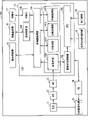
图1是表示本发明的第一实施方式~第三实施方式的摄像装置结构的方框图。FIG. 1 is a block diagram showing the configuration of imaging devices according to the first to third embodiments of the present invention.
图2是表示本发明的第一实施方式的各利用区域及有效像素区域的模式图。FIG. 2 is a schematic diagram showing respective use regions and effective pixel regions according to the first embodiment of the present invention.
图3是用于说明本发明的第一实施方式的数字照相机的操作流程图。FIG. 3 is a flowchart for explaining the operation of the digital camera according to the first embodiment of the present invention.
图4是表示本发明的第一实施方式的各显示区域及液晶监视器的可显示区域的模式图。4 is a schematic diagram showing each display area and a displayable area of a liquid crystal monitor according to the first embodiment of the present invention.
图5是用于说明本发明的第一实施方式的数字照相机的图像显示动作的流程图。5 is a flowchart for explaining the image display operation of the digital camera according to the first embodiment of the present invention.
图6是用于说明本发明的第二实施方式的数字照相机的动作的流程图。FIG. 6 is a flowchart for explaining the operation of the digital camera according to the second embodiment of the present invention.
图7是表示本发明的第二实施方式的固体摄像元件的读取行的模式图。FIG. 7 is a schematic diagram showing a read line of a solid-state imaging device according to a second embodiment of the present invention.
图8是表示本发明的第三实施方式的第一实施例的各利用区域及有效像素区域的模式图。FIG. 8 is a schematic diagram showing respective use regions and effective pixel regions in the first example of the third embodiment of the present invention.
图9表示本发明的第三实施方式的第二实施例的各利用区域及有效像素区域的模式图。FIG. 9 is a schematic diagram showing each used area and effective pixel area in Example 2 of the third embodiment of the present invention.
图10表示本发明的第三实施方式的第三实施例的各利用区域及有效像素区域的模式图。FIG. 10 is a schematic diagram showing each used area and effective pixel area in Example 3 of the third embodiment of the present invention.
图11是用于说明本发明的第四实施方式的第一实施例的数字照相机的动作的流程图。11 is a flowchart for explaining the operation of the digital camera of the first example of the fourth embodiment of the present invention.
图12是用于说明本发明的第四实施方式的第二实施例的数字照相机的动作的流程图。12 is a flowchart for explaining the operation of the digital camera of the second example of the fourth embodiment of the present invention.
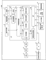
图13是表示本发明的第五实施方式的摄像装置的结构的方框图。FIG. 13 is a block diagram showing the configuration of an imaging device according to a fifth embodiment of the present invention.
图14是用于说明本发明的第五实施方式的数字照相机的动作的流程图。FIG. 14 is a flowchart for explaining the operation of the digital camera according to the fifth embodiment of the present invention.
图15是表示相关技术1的各利用区域及有效像素区域的模式图。FIG. 15 is a schematic diagram showing respective use regions and effective pixel regions in related art 1. FIG.
图16是表示相关技术2的各利用区域及有效像素区域的模式图。FIG. 16 is a schematic diagram showing respective use regions and effective pixel regions in
最佳实施方式best practice
第一实施方式:First implementation mode:
[1-1.结构][1-1. Structure]
[1-1-1.装置结构][1-1-1. Device structure]
本发明的第一实施方式涉及的数字照相机100,能够选择不同的纵横比模式,拍摄具有与已选择模式对应的纵横比的图像数据。例如,能够选择16∶9、3∶2、4∶3等纵横比模式,在选择了16∶9的纵横比模式的情况下,将16∶9的纵横比的图像数据作为记录用图像数据存储在存储卡17中。The
图1是表示本发明的第一实施方式的数字照相机100结构的方框图。如图1所示,数字照相机100包括:CCD(电荷耦合器件,charge coupled device)图像传感器(以下简称为CCD)11、模拟前端电路部(以下称为AFE)12、模拟数字转换器(以下简称为ADC)13、LSI(大规模集成电路,large-scaleintegration)14、缓冲存储器15、液晶监视器16、存储卡17、纵横比切换操作部18、快门按钮19、时序发生器(以下称TG)20及CCD驱动电路21。FIG. 1 is a block diagram showing the configuration of a
CCD 11是多个像素被二维排列的固体摄像元件。CCD 11输出由各像素生成的图像数据。AFE 12是对从CCD 1输出的图像数据进行称为CDS的噪声消除处理的一种放大器。ADC 13将从AFE 12输出的图像数据从模拟形式转换为数字形式的信号。The
LSI 14包含图像处理部141、CPU(中央处理单元,central Processingunit)142、图像特征检测部143、存储器管理部144、显示控制部145及卡接口146。The
图像处理部141使用由CCD上的像素生成的图像数据、或者用AFE 12及ADC 13对该图像数据实施了规定处理的图像数据,生成记录用图像数据。图像处理部141包含前处理部1411、YC处理部1412、变焦处理部1413及压缩处理部1414。The
上述前处理部1411执行从ADC 13输出的图像数据的黑平衡补偿等。由前处理部1411处理的图像数据经存储器管理部144暂时存储在缓冲存储器15。The above-mentioned
YC处理部1412对存储在缓冲存储器15的图像数据实施YC处理,生成包含YC信号的图像数据。The
变焦处理部1413变换实施了YC处理的图像数据的分辨率。变焦处理部1413执行所谓的电子变焦处理。因此,能够实现图像的放大或缩小。此外,图像数据的分辨率变换既可以通过剔除处理执行,也可以通过内插处理执行,或通过剔除处理及内插处理两者执行。The
压缩处理部1414对由YC处理部1412进行了YC处理的图像数据、或者由变焦处理部1413进行了分辨率变换的图像数据进行压缩处理。压缩处理形式例如是JPEG压缩形式。The
CPU142(控制部件)由微型电子计算机等构成,根据快门按钮19及纵横比切换操作部18等操作部件接收的指示,控制整个数字照相机100。例如,当快门按钮19被施加半压操作时,CPU 142根据由图像特征检测部143检测出的图像特征,计算出自动聚焦的评价值。The CPU 142 (control means) is composed of a microcomputer or the like, and controls the entire
存储器管理部144执行缓冲存储器15的写入及读取的管理、以及图像处理部141中的各处理部1411~1414的输入输出管理。由此,能够圆滑地进行使用了缓冲存储器15的图像处理部141中的图像处理,能够期待迅速的处理。The
显示控制部145控制液晶监视器16的显示。The
卡接口146是与存储卡17的接口。卡接口146执行向存储卡17写入数据的控制和从存储卡17读取数据的控制。The
缓冲存储器15(存储部件)包含DRAM、或闪存器等半导体存储器而构成。缓冲存储器15暂时存储由图像处理部141处理的图像数据,协助图像处理部141的处理。The buffer memory 15 (storage means) includes a semiconductor memory such as a DRAM or a flash memory. The
液晶监视器16显示由CCD 11生成的图像数据、或者对该图像数据实施了规定处理的图像数据。此外,液晶监视器16能够显示存储在存储卡17中的图像数据。此外,液晶监视器16能够显示为了使用者的操作而使用的各种信息。The liquid crystal monitor 16 displays image data generated by the
存储卡17能够存储由图像处理部141生成的记录用图像数据。The
纵横比切换操作部18(模式设定部件)切换可设定为16∶9的纵横比的模式、可设定为3∶2的纵横比的模式、可设定为4∶3的纵横比的模式,能够设定为任一种模式。纵横比切换操作部18也可以由旋转拨号盘、滑动开关等机械的设定机构构成。此外,纵横比切换操作部18也可以是显示在液晶监视器16上进行设定的结构。The aspect ratio switching operation part 18 (mode setting means) switches between a mode that can be set to an aspect ratio of 16:9, a mode that can be set to an aspect ratio of 3:2, and a mode that can be set to an aspect ratio of 4:3. Mode, can be set to any mode. The aspect ratio switching
TG 20是产生时序信号的时序发生器。TG 20根据LSI 14的控制产生时序信号。在TG 20产生的时序信号输入到CCD驱动电路21,用于CCD 11的控制。此外,在TG 20产生的时序信号还输入到LSI,LSI 14按照CCD 11的驱动时序来控制图像处理部141等。
[1-1-2.CCD的利用区域][1-1-2. CCD utilization area]
生成图像数据的CCD图像传感器上的像素区域(以下称为利用区域)对每个纵横比模式不同,上述图像数据在图像处理部141生成记录用图像数据时使用。下面,详细说明这一点。A pixel area on the CCD image sensor for generating image data (hereinafter referred to as a used area) differs for each aspect ratio mode, and the image data is used when the
图2是表示CCD 11上的像素区域的模式图。图2A表示16∶9模式时的利用区域(以下称为利用区域E1)。图2B表示4∶3模式时的利用区域(以下称为利用区域E2)。图2C表示3∶2模式时的利用区域(以下称为利用区域E3)。此外,图2D是表示各模式的利用区域间的关系、各模式的利用区域E1~E3和CCD 11上的有效像素区域的关系的模式图。FIG. 2 is a schematic diagram showing a pixel area on the
如图2A所示,利用区域E1由具有宽H1、高V1、对角长度φ1尺寸的像素构成。而且,H1/V1大致等于16/9的值。此外,如图2B所示,利用区域E2由具有宽H2、高V2、对角长度φ2尺寸的像素构成,H2/V2大致等于4/3的值。此外,如图2C所示,利用区域E3由具有宽H3、高V3、对角长度φ3尺寸的像素构成,,H3/V3大致等于3/2的值。As shown in FIG. 2A , the utilization area E1 is composed of pixels having dimensions of width H1 , height V1 , and diagonal length φ1 . Also, H1/V1 is approximately equal to a value of 16/9. In addition, as shown in FIG. 2B , the utilization area E2 is composed of pixels having dimensions of width H2, height V2, and diagonal length φ2, and H2/V2 is approximately equal to a value of 4/3. In addition, as shown in FIG. 2C, the utilization area E3 is composed of pixels having dimensions of width H3, height V3, and diagonal length φ3, and H3/V3 is approximately equal to a value of 3/2.
而且,如图2D所示,利用区域E1和E2的尺寸具有如下关系:Moreover, as shown in FIG. 2D, the dimensions of the utilization areas E1 and E2 have the following relationship:
H2<H1 …(数学式1)H2<H1 ...(Mathematical formula 1)
V1<V2 …(数学式2)V1<V2 ...(Mathematical formula 2)
即,在纵横比互不相同的利用区域之间,使一方的利用区域的宽度比另一方的利用区域的宽度大,并且,使另一方的利用区域的高度比一方的利用区域的高度大。That is, among use areas with different aspect ratios, one use area has a wider width than the other use area, and the other use area has a greater height than one use area.
如下所示,此关系在利用区域E2-E3间和利用区域E1-E3之间也成立。As shown below, this relationship is also established between the usage areas E2-E3 and between the usage areas E1-E3.
H2<H3 …(数学式3)H2<H3 ...(Mathematical formula 3)
V3<V2 …(数学式4)V3<V2 ...(mathematical formula 4)
H3<H1 …(数学式5)H3<H1 ...(mathematical formula 5)
V1<V3 …(数学式6)V1<V3 ...(Mathematical formula 6)
此外,此关系在3个以上的利用区域之间也成立。In addition, this relationship is also established between three or more utilization areas.
H2<H3<H1 …(数学式7)H2<H3<H1 ...(mathematical formula 7)
V1<V3<V2 …(数学式8)V1<V3<V2 ... (mathematical formula 8)
如此,在纵横比互不相同的利用区域之间,使一方的利用区域的宽度比另一方的利用区域的宽度大,并且,使另一方的利用区域的高度比一方的利用区域的高度大,由此能够使各纵横比模式中的利用区域内的像素数彼此接近。因此,即使纵横比模式不同,也能够使记录用图像的容量或像质彼此接近。In this way, among the use areas with different aspect ratios, the width of one use area is made larger than the width of the other use area, and the height of the other use area is made larger than the height of one use area, Thereby, the number of pixels in the use area in each aspect ratio mode can be made close to each other. Therefore, even if the aspect ratio modes are different, the capacity and image quality of the images for recording can be made close to each other.
要求上述H1~H3及V1~V3满足如下条件:使纵横比H1/V1、H2/V2、H3/V3分别保持16/9、4/3及3/2的固定值,并且,在各模式之间利用区域E1~E3内的像素数目相等。其中,利用区域内的像素数不需要准确地相等,只要是大致相等的值即可。例如,各模式的利用区域内的像素数的差异和各模式的利用区域内的像素数的比例在10%以内,就可以称为大致相等。The above-mentioned H1~H3 and V1~V3 are required to meet the following conditions: the aspect ratios H1/V1, H2/V2, and H3/V3 are kept at fixed values of 16/9, 4/3, and 3/2, respectively; The number of pixels in the utilization areas E1-E3 is equal. However, the number of pixels in the utilization area does not need to be exactly equal, but may be substantially equal. For example, if the difference in the number of pixels in the use area of each mode and the ratio of the number of pixels in the use area of each mode are within 10%, it can be said that they are substantially equal.
此外,也可以是,在各模式之间,并不是使利用区域E1~E3内的像素数直接相等,而是使各利用区域的对角长度φ1~φ3分别相等。由此,就能够简单地使各纵横比模式中的利用区域内的像素数大致均匀地一致。此外,由于各纵横比图像间的对角线视角大致恒定,所以即使切换纵横比模式,也能够有效地利用镜头的有效像圈。In addition, instead of directly making the number of pixels in the utilization areas E1 to E3 equal between the modes, the diagonal lengths φ1 to φ3 of the respective utilization areas may be equal to each other. Thereby, the number of pixels in the utilization area in each aspect ratio mode can be easily made substantially uniform. In addition, since the diagonal angle of view between images of each aspect ratio is approximately constant, the effective image circle of the lens can be effectively used even if the aspect ratio mode is switched.
再有,即使在对角长度φ1~φ3下,也没必要准确地相等,只要是大致相等的数值即可。例如,如果各模式的利用区域的对角长度的差异和各模式的利用区域的对角长度的比例在10%以内,就可以称为大致相等。In addition, even in the case of the diagonal lengths φ1 to φ3, it is not necessary to be exactly equal, and it is sufficient as long as they are approximately equal in value. For example, if the difference in the diagonal length of the utilization area of each mode and the ratio of the diagonal length of the utilization area of each mode are within 10%, it can be said to be approximately equal.
再有,CCD图像传感器11是本发明的固体摄像元件的一个例子。纵横比切换操作部18是本发明的模式设定部件(模式设定单元)的一个例子。图像处理部14是本发明的图像处理部件(图像处理单元)的一个例子。快门按钮19是本发明的接收部件(快门释放单元)的一个例子。液晶监视器16是本发明的显示部件(显示器件)的一个例子。显示控制部145是本发明的显示控制部件(显示器件驱动器)的一个例子。In addition, the
[1-2.动作][1-2. Action]
接着,参照图3说明第一实施方式涉及的数字照相机100的动作。Next, the operation of the
操作者操作纵横比切换操作部18,在摄像动作开始前预先设定纵横比模式。然后,当操作者对快门按钮19进行半压操作后进行全压操作(S11)时,开始数字照相机100的摄像动作,开始CCD 11的曝光动作。The operator operates the aspect ratio switching
当开始摄像动作时,CPU142确认纵横比模式被设定为16∶9、4∶3、3∶2中的哪一个(S12)。接着,CPU142结束CCD11的曝光动作。此后,CPU142命令TG20产生时序信号。从TG20产生的时序信号是能够将与设定的纵横比对应的像素区域的图像数据从CCD 11输出的信号(S13)。即,CPU142通过调整TG20的时序信号就能够切换CCD11的利用区域来读取。例如,当纵横比模式是16∶9时,TG20根据来自CPU142的命令,生成能够从CCD 11读取图2A所示像素的时序信号。When the imaging operation is started, the
CCD驱动电路21接收来自TG 20的时序信号,驱动CCD11(S14)。由此,CCD11输出由对应于纵横比模式的利用区域的像素生成的图像数据。The
利用AFE12对从CCD11读取的图像数据进行CDS处理。利用ADC13对经CDS处理的图像数据进行数字化。利用前处理部1411对经数字化的图像数据进行前处理(S15)。经过了前处理的图像数据暂时存储在缓冲存储器15中,此后,根据需要实施YC处理、变焦处理、压缩处理等,生成记录用图像数据(S16)。Image data read from the
生成的记录用图像数据被写入存储卡17(S17)。然后,显示控制部145在液晶监视器16上显示对应于记录用图像数据的图像(S18)。The generated image data for recording is written in the memory card 17 (S17). Then, the
下面,参照图4、图5,说明向液晶监视器16进行图像显示的动作。图4是表示液晶监视器16上的显示区域的模式图。在图4中,图4A表示16∶9模式时的显示区域(以下称为显示区域P1)。图4B表示4∶3模式时的显示区域(以下称为显示区域P2)。图4C表示3∶2模式时的显示区域(以下称为显示区域P3)。此外,图4D是表示各模式的显示区域间的关系、各模式的显示区域P1~P3和液晶监视器16上的显示像素区域的关系的模式图。Next, the operation of displaying an image on the liquid crystal monitor 16 will be described with reference to FIGS. 4 and 5 . FIG. 4 is a schematic diagram showing a display area on the
如图4A所示,显示区域P1由具有宽PH1、高PV1、对角长度Pφ1的尺寸的像素构成。而且,PH1/PV1大致等于16/9的值。此外,如图4B所示,显示区域P2由具有宽PH2、高PV2、对角长度Pφ2的尺寸的像素构成,PH2/PV2大致等于4/3的值。此外,如图4C所示,显示区域P3由具有宽PH3、高PV3、对角长度Pφ3的尺寸的像素构成,PH3/PV3大致等于3/2的值。As shown in FIG. 4A , the display region P1 is composed of pixels having dimensions of a width PH1 , a height PV1 , and a diagonal length Pφ1 . Also, PH1/PV1 is approximately equal to a value of 16/9. Furthermore, as shown in FIG. 4B , the display area P2 is composed of pixels having dimensions of width PH2, height PV2, and diagonal length Pφ2, and PH2/PV2 is approximately equal to a value of 4/3. In addition, as shown in FIG. 4C , the display area P3 is composed of pixels having dimensions of width PH3 , height PV3 , and diagonal length Pφ3 , and PH3/PV3 is approximately equal to a value of 3/2.
而且,如图4D所示,显示区域P1和P2的尺寸具有如下关系:Also, as shown in FIG. 4D, the sizes of the display areas P1 and P2 have the following relationship:
PH2<PH1 …(数学式9)PH2<PH1 ...(Mathematical formula 9)
PV1<PV2 …(数学式10)PV1<PV2 ...(Mathematical formula 10)
即,在纵横比互不相同的显示区域之间,一方的显示区域的宽度比另一方的显示区域的宽度大,并且,另一方的显示区域的高度比一方的显示区域的高度大。That is, among display areas having different aspect ratios, one display area is wider than the other display area, and the other display area is taller than the other display area.
如下所示,此关系在显示区域P2-P3间和显示区域P1-P3间也成立。As shown below, this relationship is also established between the display regions P2-P3 and between the display regions P1-P3.
PH2<PH3 …(数学式11)PH2<PH3 ...(Mathematical formula 11)
PV3<PV2 …(数学式12)PV3<PV2 ...(Mathematical formula 12)
PH3<PH1 …(数学式13)PH3<PH1 ...(Mathematical formula 13)
PV1<PV3 …(数学式14)PV1<PV3 ...(Mathematical formula 14)
此外,此关系在3个以上的显示区域间也成立。In addition, this relationship is also established between three or more display areas.
PH2<PH3<PH1 …(数学式15)PH2<PH3<PH1 ...(Mathematical formula 15)
PV1<PV3<PV2 …(数学式16)PV1<PV3<PV2 ... (Mathematical formula 16)
如此,在纵横比互不相同的显示区域间,使一方的显示区域的宽度比另一方的显示区域的宽度大,并且使另一方的显示区域的高度比一方的显示区域的高度大,由此能够使各纵横比模式中的显示区域内的像素数彼此接近。因此,即使纵横比模式不同,也能够使显示图像的像质彼此接近。此外,将图2D所示的固体摄像元件的利用区域E1~E3的关系和图4D所示的显示区域P1~P3的关系设定为相同,所以,摄像图像和显示图像的对应良好。因此,再现摄像图像时,能够消除与摄影时显示的显示图像的差别引起的不舒服感。In this way, among the display areas with different aspect ratios, one display area is wider than the other display area, and the height of the other display area is greater than the height of one display area. The number of pixels in the display area in each aspect ratio mode can be made close to each other. Therefore, even if the aspect ratio modes are different, the image quality of the displayed images can be made close to each other. Also, since the relationship between the solid-state imaging device usage regions E1 to E3 shown in FIG. 2D and the relationship between the display regions P1 to P3 shown in FIG. 4D are set to be the same, the correspondence between captured images and displayed images is good. Therefore, when reproducing the captured image, it is possible to eliminate the uncomfortable feeling caused by the difference from the displayed image displayed at the time of shooting.
要求上述PH1~PH3及PV1~PV3满足如下条件:使纵横比PH1/PV1、PH2/PV2、PH3/PV3分别保持16/9、4/3及3/2的固定值,并且,在各模式间使显示区域P1~P3内的像素数相等。其中,显示区域内的像素数不需要准确地相等,只要是大致相等的值即可。例如,各模式的显示区域内的像素数的差异和各模式的显示区域内的像素数的比例在10%以内,就可以称为大致相等。The above-mentioned PH1~PH3 and PV1~PV3 are required to meet the following conditions: keep the aspect ratios PH1/PV1, PH2/PV2, and PH3/PV3 at fixed values of 16/9, 4/3, and 3/2, respectively, and, between each mode The number of pixels in the display areas P1 to P3 is made equal. However, the number of pixels in the display area does not need to be exactly equal, but may be approximately equal. For example, if the difference in the number of pixels in the display area of each mode and the ratio of the number of pixels in the display area of each mode are within 10%, it can be said that they are substantially equal.
此外,也可以是,在各模式间显示区域P1~P3内的像素数不直接相等,而是使各显示区域的对角长度Pφ1~Pφ3分别相等。由此,能够简单地使各纵横比模式中的显示区域内的像素数大致均匀地一致。In addition, the number of pixels in the display regions P1 to P3 may not be directly equal between the modes, but the diagonal lengths Pφ1 to Pφ3 of the respective display regions may be equal to each other. Thereby, the number of pixels in the display area in each aspect ratio mode can be easily made substantially uniform.
再有,即使在对角长度Pφ1~Pφ3下,也不需要准确地相等,只要是大致相等的值即可。例如,如果各模式的显示区域的对角长度的差异和各模式的显示区域的对角长度的比例在10%以内,就可以称为大致相等。In addition, even in the case of the diagonal lengths Pφ1 to Pφ3, it is not necessary to be exactly equal, and it is sufficient if they are approximately equal. For example, if the difference in the diagonal lengths of the display areas of the respective modes and the ratio of the diagonal lengths of the display areas of the respective modes are within 10%, they can be said to be approximately equal.
图5是用于说明向液晶监视器16进行图像显示的动作的流程图。在记录用图像数据的记录中或记录之后,在液晶监视器16上显示对应于记录用图像数据的显示图像。FIG. 5 is a flowchart for explaining the operation of displaying an image on the
首先,显示控制部145从CPU142取得由纵横比切换操作部18设定的纵横比模式(S181)。接着,显示控制部145决定与取得的纵横比模式对应的显示区域(S182)。例如,如果纵横比模式是16∶9,显示控制部145决定图4所示的显示区域P1作为显示区域。接着,显示控制部145取得由YC处理部1412处理的图像数据,并将其转换成显示用图像数据(S183)。此时,显示控制部145在由步骤S182决定的显示区域内,根据图像数据生成显示整个图像的显示用图像数据。即,显示控制部145在由步骤S182决定的显示区域内对应图像数据,在其它区域对应无信号。显示控制部145向液晶监视器16输出如此生成的显示用图像数据,并显示(S184)。First, the
[1-3.本发明的第一实施方式的总结][1-3. Summary of the first embodiment of the present invention]
如上所述,本发明的第一实施方式涉及的数字照相机100包括CCD图像传感器11、纵横比切换操作部18和图像处理部141。CCD图像传感器11是由水平有效像素数H、垂直有效像素数V构成的多个像素以二维排列的固体摄像元件。As described above, the
纵横比切换操作部18是设定包含第1纵横比模式及第2纵横比模式的多个纵横比模式中的任一个的模式设定部件。在此,将16∶9的纵横比模式理解为第1纵横比模式时,在本第一实施方式中,第2纵横比模式是4∶3的纵横比模式或3∶2的纵横比模式。在16∶9的纵横比模式和4∶3的纵横比模式间,对于利用区域来说,数学式1及数学式2所示的关系成立,在16∶9的纵横比模式和3∶2的纵横比模式间,对于利用区域来说,数学式5及数学式6所示的关系成立。The aspect ratio switching
在第1纵横比模式时,图像处理部141使用由CCD 11上的像素中的水平像素数H1、垂直像素数V1的像素生成的图像数据,或者对此图像数据实施了规定处理的图像数据,生成第1记录用图像数据。另一方面,在第2纵横比模式时,图像处理部141使用由CCD11上的像素中的水平像素数H2、垂直像素数V2的像素生成的图像数据,或者对此图像数据实施了规定处理的图像数据,生成第2记录用图像数据。In the first aspect ratio mode, the
由此,就能够使第1纵横比模式及第2纵横比模式中的各利用区域内的像素数彼此接近。因此,即使纵横比模式不同,也能够使记录用图像的容量或像质彼此接近。由此,操作者在拍摄各种纵横比的图像时容易预测记录用图像的容量或像质,所以使用方便。In this way, the number of pixels in each use area in the first aspect ratio mode and the second aspect ratio mode can be made close to each other. Therefore, even if the aspect ratio modes are different, the capacity and image quality of the images for recording can be made close to each other. As a result, it is easy for the operator to predict the capacity and image quality of the image for recording when capturing images with various aspect ratios, which is convenient for use.
此外,如第一实施方式所示,也可以使各利用区域的对角长度大致相等。由此,能够容易地决定各利用区域。此外,由于各纵横比图像间的对角线视角大致恒定,所以即使切换纵横比模式,也能够有效地利用镜头的有效像圈。In addition, as shown in the first embodiment, the diagonal lengths of the respective utilization areas may be substantially equal. Thereby, each utilization area can be determined easily. In addition, since the diagonal angle of view between images of each aspect ratio is approximately constant, the effective image circle of the lens can be effectively used even if the aspect ratio mode is switched.
此外,如本第一实施方式所示,也可以是,在第1纵横比模式时,CCD 11能输出由水平像素数H1、垂直像素数V1的像素生成的图像数据,另一方面,在第2纵横比模式时,CCD 11能输出由水平像素数H2、垂直像素数V2的像素生成的图像数据。由此,在从CCD 11读取图像数据的时刻,能够获得与纵横比模式对应的纵横比的图像数据,在此后的图像处理中不会产生浪费。相反,如果在从CCD 11读取图像数据的时刻,得到与纵横比模式不对应的纵横比的图像数据,就需要从CCD11读取包含由未用于记录用图像数据的像素生成的图像数据的图像数据,在读取后的图像处理中会产生浪费。In addition, as shown in the first embodiment, it is also possible that in the first aspect ratio mode, the
此外,如本第一实施方式所示,还可以设置液晶监视器16和显示控制部145。液晶监视器16具有由水平有效像素数PH、垂直有效像素数PV构成的可显示区域,显示由CCD11生成的图像数据、或者对此图像数据实施了规定处理的图像数据。In addition, as shown in the first embodiment, a liquid crystal monitor 16 and a
在第1纵横比模式时,显示控制部145处理图像数据,以便在液晶监视器16的可显示区域中的水平像素数PH1、垂直像素数PV1的区域,显示由CCD11生成的图像数据或者对此图像数据实施了规定处理的图像数据,并生成第1显示用图像数据。另一方面,在第2纵横比模式时,显示控制部145处理图像数据,以便在液晶监视器16的可显示区域中的水平像素数PH2、垂直像素数PV2的区域,显示由CCD11生成的图像数据或者对此图像数据实施了规定处理的图像数据,并生成第2显示用图像数据。并且,满足以下关系:In the first aspect ratio mode, the
PH2<PH1≤PH、PH2<PH1≤PH,
PV1<PV2≤PV。PV1<PV2≤PV.
由此,在纵横比互不相同的显示区域间,使一方的宽度比另一方的宽度大,并且使另一方的高度比一方的高度大,由此能够使各纵横比模式中的显示区域内的像素数彼此接近。因此,即使纵横比模式不同,也能够使显示图像的像质互相接近。In this way, between display areas with different aspect ratios, one width is made larger than the other, and the height of the other is made larger than the height of the other, so that the display area in each aspect ratio mode The number of pixels are close to each other. Therefore, even if the aspect ratio modes are different, the image quality of the displayed images can be made close to each other.
此外,由于能够将固体摄像元件的利用区域E1~E3的关系和显示区域P1~P3的关系设定成相同,所以,摄像图像和显示图像的对应良好。因此,再现摄像图像时,能够消除与摄影时显示的显示图像的差别所引起的不舒服感。Also, since the relationship between the solid-state imaging device usage regions E1 to E3 and the display regions P1 to P3 can be set to be the same, the correspondence between the captured image and the displayed image is good. Therefore, when reproducing the captured image, it is possible to eliminate the uncomfortable feeling caused by the difference from the displayed image displayed at the time of shooting.
此外,如本第一实施方式所示,显示控制部145也可以从CPU142取得当前设定着的纵横比模式。由此,不需要逐一解析图像数据来求其纵横比,所以能够迅速地生成显示用图像数据。但是,即使是显示控制部145解析图像数据来求其纵横比的情况下,也适用本发明。由此,能够确实地把握对应于图像数据的纵横比。In addition, as shown in the first embodiment, the
此外,如本第一实施方式所示,纵横比模式既可以包含3个以上的模式,也可以包含2个模式。In addition, as shown in the first embodiment, the aspect ratio mode may include three or more modes, or may include two modes.
此外,纵横比模式也可以包含上述以外的纵横比的模式。例如,可以设定成为正方形图像的1∶1的纵横比模式,成为纵长图像的3∶4的纵横比模式,或成为比16∶9更长的图像的25∶9的模式等。In addition, the aspect ratio mode may also include modes of aspect ratios other than those described above. For example, it is possible to set an aspect ratio mode of 1:1 for a square image, a 3:4 aspect ratio mode for a long image, or a 25:9 mode for an image longer than 16:9.
此外,本实施方式中,固体摄像元件由CCD图像传感器构成,但不限于此,也可以替代CCD图像传感器,由CMOS图像传感器或NMOS图像传感器等的MOS传感器构成。特别地,在本第一实施方式中,不从固体摄像元件取得全部图像数据,仅取得对应于纵横比模式的图像数据,所以MOS图像传感器适合本实施方式。其理由是,由于MOS图像传感器读取像素数据的机理不同,与CCD图像传感器相比,MOS图像传感器能够容易地进行读取时的像素选择,能够容易地只读取必要区域的图像数据。In addition, in this embodiment, the solid-state imaging element is constituted by a CCD image sensor, but it is not limited thereto, and may be constituted by a MOS sensor such as a CMOS image sensor or an NMOS image sensor instead of the CCD image sensor. In particular, in the first embodiment, all image data is not acquired from the solid-state imaging device, but only image data corresponding to the aspect ratio mode is acquired, so a MOS image sensor is suitable for this embodiment. The reason for this is that MOS image sensors can easily select pixels when reading compared to CCD image sensors due to the difference in the mechanism for reading pixel data in MOS image sensors, and can easily read only image data in necessary areas.
第二实施方式:Second embodiment:
[2-1.第二实施方式的概要][2-1. Outline of the second embodiment]
本发明的第一实施方式是根据已设定的纵横比模式只读取必要区域的图像数据的结构。相对于此,本发明的第二实施方式的结构是,在图像的垂直方向根据已设定的纵横比模式只读取必要行的图像数据,另一方面,在图像的水平方向读取全部图像数据。由此,进行CCD 11的读取控制时,在水平方向不必进行复杂的控制,所以能够容易地进行读取控制。The first embodiment of the present invention is a configuration in which only image data of a necessary area is read in accordance with a set aspect ratio mode. On the other hand, the structure of the second embodiment of the present invention is such that only necessary lines of image data are read in the vertical direction of the image according to the set aspect ratio mode, and on the other hand, the entire image is read in the horizontal direction of the image. data. Thereby, when performing the reading control of the
[2-2.动作][2-2. Action]
参照图6及图7,说明本发明的第二实施方式的数字照相机100的动作。再有,本发明的第二实施方式涉及的数字照相机100的结构与本发明的第一实施方式的数字照相机100的结构相同,所以省略说明。The operation of the
图6是用于说明本发明的第二实施方式涉及的数字照相机100的动作的流程图。步骤S21及步骤S22的动作与图3所示的步骤S11及步骤S12的动作相同,所以省略说明。FIG. 6 is a flowchart for explaining the operation of the
当CCD 11的曝光动作结束时,CPU 142使TG 20产生时序信号。从TG 20产生的时序信号是用于从CCD 11输出与设定的纵横比对应的行的图像数据的信号(S23)。即,CPU 142通过调整TG 20的时序信号,能够切换CCD 11的读取行进行读取。例如,在纵横比模式为16∶9时,TG 20产生时序信号,以读取图7所示的中央的行数V1的行。When the exposure operation of the
CCD驱动电路21接收来自TG 20的时序信号,驱动CCD 11(S24)。由此,在CCD 11生成的图像数据中的上端区域L1的行的图像数据被高速传送,不读取到CCD 11的外部。中央的行数V1的行的图像数据以普通的传送速度被读取到CCD 11的外部。此外,下端区域L2的行的图像数据被高速传送,不读取到CCD 11的外部。The
在AFE 12对从CCD 11读取的图像数据进行CSD处理,在ADC 13进行数字化。被数字化的图像数据由前处理部1411进行前处理(S25)。经前处理的图像数据暂时存储在缓冲存储器15中(S26)。此时,从CCD 11读取的图像数据中的存储在缓冲存储器15的只是中央的像素数H1的图像数据。因此,只有对应于利用区域E1的图像数据被存储在缓冲存储器15中。Image data read from the
此后,根据需要实施YC处理、变焦处理、压缩处理等,生成记录用图像数据(S27)。生成的记录用图像数据写入存储卡17(S28)。然后,在液晶监视器16显示对应于记录用图像数据的图像。(S29)。Thereafter, YC processing, zoom processing, compression processing, etc. are performed as necessary to generate image data for recording (S27). The generated image data for recording is written in the memory card 17 (S28). Then, an image corresponding to the image data for recording is displayed on the
第三实施方式:The third embodiment:
[3-1.CCD的利用区域与有效像素区域的关系][3-1. Relationship between CCD utilization area and effective pixel area]
本发明的第一实施方式中,如图2D所示,利用区域E1~E3任何一个都比有效像素区域小。即,以下关系成立:In the first embodiment of the present invention, as shown in FIG. 2D , any of the utilization areas E1 to E3 is smaller than the effective pixel area. That is, the following relationship holds:
H>H1 …(数学式17)H>H1 ...(Mathematical formula 17)
V>V2 …(数学式18)V>V2 ...(Mathematical formula 18)
但是,即使在有效像素区域的宽度或/及高度与利用区域E1~E3的任一个的宽度或/及高度相等的情况下,也可以适用本发明。对于这种情况的实施例,在下文中作为第三实施方式进行说明。However, the present invention is applicable even when the width or/and height of the effective pixel region is equal to the width or/and height of any of the utilization regions E1 to E3. An example of such a case will be described below as a third embodiment.
[3-1-1.第三实施方式中的第一实施例][3-1-1. First Example in Third Embodiment]
图8是表示各模式的利用区域E1~E3间的关系,和各模式的利用区域E1~E3与CCD 11上的有效像素区域的关系的模式图。图8中,有效像素区域的宽度H设定成与利用区域E1的宽度H1相等。其它的配置与图2所示的配置相同。因此,以下关系成立:8 is a schematic diagram showing the relationship between the utilization areas E1-E3 of each mode, and the relationship between the utilization areas E1-E3 of each mode and the effective pixel area on the
H2<H3<H1=H …(数学式19)H2<H3<H1=H ...(Mathematical formula 19)
如此,通过使有效像素区域的宽度H与利用区域E1~E3中宽度最大的利用区域E1的宽度H1相等,就能够最大限度地有效活用有效像素区域的宽度方向的像素。In this way, by setting the width H of the effective pixel region equal to the width H1 of the largest utilization region E1 among the utilization regions E1 to E3, the pixels in the width direction of the effective pixel region can be effectively utilized to the maximum.
[3-1-2.第三实施方式的第二实施例][3-1-2. Second Example of Third Embodiment]
图9是表示各模式的利用区域E1~E3间的关系,和各模式的利用区域E1~E3与CCD 11上的有效像素区域的关系的模式图。图9中,有效像素区域的高度V设定成与利用区域E2的高度V2相等。其它的配置与图2所示的配置相同。因此,以下关系成立:Fig. 9 is a schematic diagram showing the relationship between the utilization areas E1-E3 of each mode, and the relationship between the utilization areas E1-E3 of each mode and the effective pixel area on the
V1<V3<V2=V …(数学式20)V1<V3<V2=V ... (Mathematical formula 20)
如此,通过使有效像素区域的高度V与利用区域E1~E3中高度最大的利用区域E2的高度V2相等,就能够最大限度地有效活用有效像素区域的高度方向的像素。In this way, by making the height V of the effective pixel region equal to the height V2 of the largest utilization region E2 among the utilization regions E1 to E3, the pixels in the height direction of the effective pixel region can be effectively utilized to the maximum.
[3-1-3.第三实施方式的第三实施例][3-1-3. Third Example of Third Embodiment]
图10是表示各模式的利用区域E1~E3间的关系,和各模式的利用区域E1~E3与CCD 11上的有效像素区域的关系的模式图。图10中,有效像素区域的宽度H设定成与利用区域E1的宽度H1相等。此外,有效像素区域的高度V设定成与利用区域E2的高度V2相等。其它的配置与图2所示的配置相同。因此,满足上述数学式19及数学式20的两者。Fig. 10 is a schematic diagram showing the relationship between the utilization areas E1-E3 of each mode, and the relationship between the utilization areas E1-E3 of each mode and the effective pixel area on the
如此,通过使有效像素区域的宽度H与利用区域E1~E3中宽度最大的利用区域E1的宽度H1相等,并且使有效像素区域的高度V与利用区域E1~E3中高度最大的利用区域E2的高度V2相等,能够最大限度地有效活用有效像素区域的像素。In this way, by making the width H of the effective pixel region equal to the width H1 of the largest utilization region E1 among the utilization regions E1 to E3, and making the height V of the effective pixel region equal to that of the utilization region E2 having the largest height among the utilization regions E1 to E3 The height V2 is equal, and the pixels in the effective pixel area can be effectively utilized to the maximum extent.
[3-2.第三实施方式的总结][3-2. Summary of Third Embodiment]
如上所述,根据本第三实施方式,有效像素区域的宽度或/及高度可以和利用区域E1~E3中任一个的宽度或/及高度相等。由此,能够最大限度地有效活用有效像素区域的像素。As described above, according to the third embodiment, the width or/and height of the effective pixel area may be equal to the width or/and height of any one of the utilization areas E1 to E3. As a result, the pixels in the effective pixel region can be effectively utilized to the maximum.
第四实施方式:Fourth embodiment:
[4-1.来自CCD 11的图像数据的读取区域][4-1. Reading area of image data from CCD 11]
本发明的第一实施方式中,从CCD 11读取由对应于纵横比模式的利用区域的像素生成的图像数据。但是,与纵横比模式无关地,一旦读取在全部有效像素区域生成的图像数据,之后根据纵横比模式生成记录用图像数据,也可以适用本发明。对于这种情况的实施例,在下文中作为本发明的第四实施方式加以说明。In the first embodiment of the present invention, image data generated by pixels corresponding to the utilization area of the aspect ratio mode is read from the
再有,本发明的第四实施方式中的数字照相机的结构与本发明的第一实施方式中的数字照相机100的结构相同,所以下面省略其结构的说明。In addition, the structure of the digital camera in the fourth embodiment of the present invention is the same as that of the
[4-1-1。第四实施方式的第一实施例][4-1-1. First Example of Fourth Embodiment]
图11是用于说明本第一实施例涉及的数字照相机的动作的流程图。参照图11,说明本第一实施例的数字照相机的动作。FIG. 11 is a flowchart for explaining the operation of the digital camera according to the first embodiment. Referring to Fig. 11, the operation of the digital camera of the first embodiment will be described.
操作者操作纵横比切换操作部18,在摄像动作开始前预先设定纵横比模式。然后,当操作者对快门按钮19进行半压操作之后,进行全压操作(S31)时,在数字照相机100中开始摄像动作。The operator operates the aspect ratio switching
当摄像动作开始时,CPU 142确认纵横比模式设定为16∶9、4∶3、3∶2中的任一个(S32)。接着,CPU 142结束CCD 11的曝光动作。When the imaging operation starts, the
接着,CCD驱动电路21接收来自TG 20的时序信号,驱动CCD 11。CCD 11根据来自CCD驱动电路21的控制,输出由全部有效像素区域的像素生成的图像数据(S33)。Next, the
从CCD 11读取的图像数据,由AFE 12进行CDS处理,由ADC 13进行数字化。被数字化的图像数据,由前处理部1411进行前处理(S34)。Image data read from the
接着,存储器管理部144通过CPU 142的控制,从由前处理部1411处理的全部有效像素区域的图像数据中切出由对应于纵横比模式的利用区域(利用区域E1~E3的任一个)的像素生成的图像数据,并存储在缓冲存储器15中。因此,缓冲存储器15暂时存储由对应于纵横比模式的利用区域的像素所生成的、由AFE 12、ADC 13及前处理部1411实施了规定处理的图像数据。例如,纵横比模式是16∶9的情况下,存储器管理部144通过CPU 142的控制,从由前处理部1411处理的全体有效像素区域的图像数据中切出由利用区域E1的像素生成的图像数据,并存储在缓冲存储器15中(S35)。Next, under the control of the
此后,根据需要实施YC处理、变焦处理、压缩处理等,生成记录用图像数据(S36)。Thereafter, YC processing, zoom processing, compression processing, etc. are performed as necessary to generate image data for recording (S36).
生成的记录用图像数据被写入存储卡17(S37)。然后,在液晶监视器16显示对应于记录用图像数据的图像(S38)。The generated image data for recording is written in the memory card 17 (S37). Then, an image corresponding to the recording image data is displayed on the liquid crystal monitor 16 (S38).
如上所述,本第一实施例中,从CCD 11读取全部有效像素区域的图像数据,所以不需要复杂地控制TG 20,因此能够容易地执行从CCD 11的图像数据的读取。As described above, in the present first embodiment, the image data of the entire effective pixel area is read from the
此外,本第一实施例中,是将在对应于纵横比模式的利用区域生成的图像数据、或者对该图像数据实施了规定处理的图像数据存储在缓冲存储器15中的结构,所以,与将在全部有效像素区域生成的图像数据全部存储的情况相比,能够减少存储图像数据所需要的存储容量。In addition, in the first embodiment, the image data generated in the use area corresponding to the aspect ratio mode or the image data subjected to predetermined processing on the image data is stored in the
[4-1-2.第四实施方式的第二实施例][4-1-2. Second Example of Fourth Embodiment]
图12是用于说明本第二实施例涉及的数字照相机的动作的流程图。参照图12说明本第二实施例的数字照相机的动作。FIG. 12 is a flowchart for explaining the operation of the digital camera according to the second embodiment. The operation of the digital camera of the second embodiment will be described with reference to FIG. 12 .
操作者操作纵横比切换操作部18,在摄像动作开始前预先设定纵横比模式。然后,当操作者对快门按钮19进行半压操作之后,进行全压操作(S41)时,在数字照相机100中开始摄像动作。The operator operates the aspect ratio switching
当摄像动作开始时,CPU 142确认纵横比模式设定为16∶9、4∶3、3∶2中的任一个(S42)。接着,CPU 142结束CCD 11的曝光动作。When the imaging operation starts, the
接着,CCD驱动电路21接收来自TG 20的时序信号,驱动CCD 11。CCD 11通过来自CCD驱动电路21的控制,输出由全部有效像素区域的像素生成的图像数据(S43)。Next, the
从CCD 11读取的图像数据,由AFE 12进行CDS处理,由ADC 13进行数字化。被数字化的图像数据,由前处理部1411进行前处理(S44)。Image data read from the
接着,存储器管理部144将由前处理部1411处理过的图像数据存储在缓冲存储器15中(S45)。因此,缓冲存储器15暂时存储由有效像素区域的像素生成的、由AFE 12、ADC 13及前处理部1411实施了规定处理的全部图像数据。Next, the
接着,存储器管理部144通过CPU 142的控制,从存储在缓冲存储器15的有效像素区域的全部图像数据中切出由对应于纵横比模式的利用区域(利用区域E1~E3的任一个)的像素生成的图像数据,并输出到图像处理部141(S46)。例如,在纵横比模式是16∶9的情况下,存储器管理部144通过CPU142的控制切出由利用区域E1的像素生成并实施了规定处理的图像数据,输出到图像处理部141。Next, under the control of the
之后,根据需要实施YC处理、变焦处理、压缩处理等,生成记录用图像数据(S47)。Thereafter, YC processing, zoom processing, compression processing, etc. are performed as necessary to generate image data for recording (S47).
生成的记录用图像数据被写入存储卡17中(S48)。然后,在液晶监视器16显示对应于记录用图像数据的图像(S49)。The generated image data for recording is written in the memory card 17 (S48). Then, an image corresponding to the recording image data is displayed on the liquid crystal monitor 16 (S49).
再有,也可以在图像处理步骤的任何阶段进行与上述纵横比模式对应的必要图像数据的切出处理。例如,可以在YC处理之前进行,也可以是,对全部有效像素进行YC处理,在变焦处理时切出。In addition, the necessary image data cutout processing corresponding to the above-mentioned aspect ratio mode may be performed at any stage of the image processing procedure. For example, YC processing may be performed before YC processing, or YC processing may be performed on all effective pixels and cut out during zoom processing.
此外,也可以是,对全部有效像素进行YC处理及变焦处理,在压缩处理前进行切出处理。In addition, YC processing and zoom processing may be performed on all effective pixels, and cropping processing may be performed before compression processing.
此外,也可以是,对全部有效像素进行所有图像处理,之后在向存储卡17写入时进行切出处理。In addition, all image processing may be performed on all effective pixels, and then cutting out processing may be performed when writing to the
如上所述,本第二实施例中,一旦将全部有效像素区域的图像数据全部存储在缓冲存储器15,因此能够自由地进行此后的图像数据的加工。例如,能够在存储到缓冲存储器15之后,变更纵横比模式。这是因为,必要的图像数据全都存储在缓冲存储器15中。As described above, in the second embodiment, once all the image data of all the effective pixel regions are stored in the
[4-2.第四实施方式的总结][4-2. Summary of Fourth Embodiment]
本发明的第四实施方式涉及的数字照相机除了具有CCD 11、纵横比切换操作部18和图像处理部141之外,还包括缓冲存储器15。The digital camera according to the fourth embodiment of the present invention includes a
缓冲存储器15暂时存储由CCD 11上的水平有效像素数H、垂直有效像素数V构成的多个像素生成的图像数据,或者对该图像数据实施了规定处理的图像数据。而且,在第1纵横比模式时,图像处理部14读取存储在缓冲存储器15的图像数据中的、对应于水平像素数目H1及垂直像素数目V1的像素的图像数据,生成第1记录用图像数据。另一方面,在第2纵横比模式时,图像处理部14读取存储在缓冲存储器15的图像数据中的、对应于水平像素数H2及垂直像素数V2的像素的图像数据,生成第2记录用图像数据。The
由此,本第四实施方式的结构中,从CCD 11读取全部有效像素区域的图像数据,所以不需要复杂地控制TG 20,因此能够容易地执行从CCD 11的图像数据读取。Thus, in the structure of the fourth embodiment, the image data of the entire effective pixel area is read from the
第五实施方式:Fifth embodiment:
[5-1.结构][5-1. Structure]
本发明的第五实施方式的数字照相机400可以根据纵横比进行阶层摄像。下面,参照图13及图14说明第五实施方式。The
图13是表示本第五实施方式的数字照相机400的结构的方框图。阶层设定部22是用于设定纵横比阶层模式的的部件。图像选择部24是用于选择在纵横比阶层模式下生成的纵横比不同的多个图像中的任一个的部件。其它结构与本发明的第一实施方式的数字照相机100相同,所以省略其说明。FIG. 13 is a block diagram showing the configuration of a
[5-2.动作][5-2. Action]
下面,参照图14,说明本第五实施方式的数字照相机400的动作。Next, the operation of the
首先,操作者预先操作阶层设定部22,预先设定纵横比阶层模式(S51)。然后,当操作者对快门按钮19进行半压操作之后,进行全压操作(S52)时,在数字照相机400中开始纵横比阶层模式的摄像操作。First, the operator operates the
当摄像动作开始时,CPU 142开始CCD 11的曝光动作。之后,CCD驱动电路21接收来自TG 20的时序信号,驱动CCD 11。CCD 11输出由全部有效像素区域的像素生成的图像数据(S53)。When the imaging operation starts, the
从CCD 11读取的图像数据,由AFE 12进行CDS处理,由ADC 13进行数字化。被数字化的图像数据,由前处理部1411进行前处理(S54)。Image data read from the
接着,存储器管理部144将由前处理部1411处理过的图像数据存储在缓冲存储器15中(S55)。因此,缓冲存储器15暂时存储由有效像素区域的像素生成的、由AFE 12、ADC 13及前处理部1411实施了规定处理的全部图像数据。Next, the
接着,依次生成纵横比互不相同的图像。首先,存储器管理部144通过CPU 142的控制,从存储在缓冲存储器15的有效像素区域的全部图像数据中切出由对应于最初纵横比的利用区域E的像素生成的图像数据,输出到图像处理部141(S56)。Next, images having different aspect ratios are sequentially generated. First, under the control of the
然后,YC处理单元1412对从缓冲存储器15读取的对应于利用区域E1的图像数据实施YC处理(S57)。Then, the
将生成的YC数据存储在缓冲存储器15中(S58)。The generated YC data is stored in the buffer memory 15 (S58).
以上的步骤S56到S58的动作,对于与其余的纵横比的利用区域E2及E3对应的图像数据也同样地重复(S59)。The operations of steps S56 to S58 described above are similarly repeated for the image data corresponding to the remaining aspect-ratio utilization regions E2 and E3 (S59).
对所有纵横比的上述动作结束时,CPU 142进行将各纵横比的YC图像显示在液晶监视器16的控制。然后,图像选择部24接收操作者的有关图像选择的指示,选择存储在缓冲存储器15中的纵横比不同的多个图像数据中的任一个(S60)。When the above-mentioned operations for all aspect ratios are completed, the
接着,压缩处理单元1414对由图像选择部24选择的图像数据进行压缩处理,生成记录用图像数据(S61)。此时,也可以进行变焦处理部1413的变焦处理。或者,也可以在图像选择前进行变焦处理。Next, the
然后,生成的记录用图像数据被写入存储卡17(S62)。Then, the generated image data for recording is written in the memory card 17 (S62).
再有,可以在图像处理步骤的任何阶段进行提与上述纵横比模式对应的必要图像数据的切出处理。例如,可以在YC处理前进行,也可以是对全部有效像素进行YC处理,在变焦处理时切出。In addition, the cutout processing to provide necessary image data corresponding to the above-mentioned aspect ratio mode may be performed at any stage of the image processing steps. For example, YC processing may be performed before YC processing, or YC processing may be performed on all effective pixels and cut out during zoom processing.
此外,也可以是,对全部有效像素进行YC处理及变焦处理,在压缩处理前进行切出处理。In addition, YC processing and zoom processing may be performed on all effective pixels, and cropping processing may be performed before compression processing.
此外,也可以是,对全部有效像素进行所有图像处理之后,在向存储卡17写入时进行切出处理。In addition, after all image processing is performed on all effective pixels, cropping processing may be performed when writing to the
[5-3.第五实施方式的总结][5-3. Summary of Fifth Embodiment]
如上所述,本发明的第五实施方式的数字照相机400包括CCD 11、图像处理部141、阶层设定部22和快门按钮19。阶层设定部22可以设定纵横比阶层模式。在通过阶层设定部22设定纵横比阶层模式的情况下,当快门按钮19接收到摄像开始的指示时,图像处理部141生成纵横比各不相同的多个记录用图像数据。As described above, the
由此,对于相同的摄像对象能够生成多张纵横比不同的记录用图像数据,因此可以在摄像后选择适合于摄像对象的纵横比的图像。所以,能够实现失败少的摄像。In this way, a plurality of pieces of image data for recording having different aspect ratios can be generated for the same imaging target, so that an image with an aspect ratio suitable for the imaging target can be selected after imaging. Therefore, imaging with few failures can be realized.
此外,本发明如本第五实施方式所示,优选还具有暂时存储由CCD11上的多个像素生成的图像数据、或者对该图像数据实施了规定处理的图像数据的缓冲存储器15。该情况下,也可以是,当在设定了纵横比阶层模式的情况下快门按钮19接受了摄像开始的指示时,图像处理部141分别读取存储在缓冲存储器15的图像数据中的、与多个纵横比的像素排列对应的图像数据,生成纵横比各不相同的多个记录用图像数据。In addition, as shown in the fifth embodiment, the present invention preferably further includes a
第六实施方式:Sixth embodiment:
接着,说明本发明的第六实施方式。第六实施方式是第一实施方式~第五实施方式的变化例。Next, a sixth embodiment of the present invention will be described. The sixth embodiment is a modified example of the first to fifth embodiments.
本发明的第一实施方式~第五实施方式中,固体摄像元件由CCD图像传感器11构成,但不限于此,也可以由多个像素以二维排列的图像传感器构成。例如,也可以是CMOS图像传感器等。In the first to fifth embodiments of the present invention, the solid-state imaging device is constituted by the
此外,本发明的第一实施方式~第五实施方式中,说明了将CCD 11和CCD驱动电路21作为单独的构成要素的情况,但这些也可以用1个半导体器件构成。In addition, in the first embodiment to the fifth embodiment of the present invention, the case where the
此外,也可以用1个部件构成TG 20和CCD驱动电路21。In addition, the
本发明的第一实施方式~第五实施方式中,是在图像处理前进行CDS处理(噪声消除处理)和ADC转换处理的结构,但不限于此。例如,可以直接用前处理部1411处理从CCD 11读取的图像数据,也可以存储在缓冲存储器15中。此外,也可以在图像处理前进行其它的处理。In the first to fifth embodiments of the present invention, CDS processing (noise removal processing) and ADC conversion processing are performed before image processing, but the present invention is not limited thereto. For example, the image data read from the
本发明的第一实施方式~第五实施方式中,说明了在同一LSI 14上实现图像处理部141和CPU 142等的例子,但不限定于此。各部位也可以分别单独形成。或者,也可以分成多个组形成。例如,可以用1个DSP(数字信号处理器,Digital Signal Processor)构成图像处理部141,也可以用1个微型电子计算机构成CPU 142其它部分。In the first to fifth embodiments of the present invention, examples were described in which the
本发明的第一实施方式~第五实施方式中,例示了图像处理部件实施YC处理、分辨率变换处理、压缩处理等的结构,但不限于此。图像处理部件只要是使用由CCD 11上的像素生成的图像数据来生成记录用图像数据就可以,本发明的图像处理部件也包含不实施YC处理、分辨率变换处理、压缩处理等的结构。此外,在本发明的图像处理部件还包含进行JPEG以外的其它压缩处理的结构。即,YC处理、分辨率变换处理、压缩处理等是图像处理的示例。因此,即使在记录用图像数据是非压缩形式的图像数据的情况下、或者是运动图像的情况下,都可以适用本发明。此外,也可以根据情况,有时认为前处理之前的CDS处理(噪声消除处理)或ADC转换等是图像处理的一部分。In the first to fifth embodiments of the present invention, configurations in which the image processing means performs YC processing, resolution conversion processing, compression processing, and the like are exemplified, but the present invention is not limited thereto. As long as the image processing unit generates image data for recording using image data generated by pixels on the
图像处理部14可以仅仅是硬件结构,或者是组合硬件和软件的结构。The
本发明的第一实施方式~第五实施方式是由存储器管理部144管理向缓冲存储器15等的输入输出的结构,但不限于此,例如CPU 142也可以进行这些管理。In the first to fifth embodiments of the present invention, the
本发明的第一实施方式~第五实施方式中,缓冲存储器15是1个的结构,但也可以是设置多个缓冲存储器15的结构。In the first to fifth embodiments of the present invention, one
本发明的第一实施方式~第五实施方式中,显示部件例示了液晶监视器16,但不限于此,也可以是有机EL(electro-luminescence)显示器和无机EL显示器等。In the first to fifth embodiments of the present invention, the liquid crystal monitor 16 was exemplified as the display means, but is not limited thereto, and may be an organic EL (electro-luminescence) display, an inorganic EL display, or the like.
本发明的第一实施方式~第五实施方式中,例示了在存储卡17中存储记录用图像数据的结构,但不限于此。例如,也可以将记录用图像数据存储在内置于摄像装置内的内置存储器中。在此情况下,可以与缓冲存储器15分开设置内置存储器。此外,也可以将缓冲存储器15兼用作暂时记录用和记录用图像数据的记录用这两方面。In the first to fifth embodiments of the present invention, the configuration in which image data for recording is stored in the
本第一实施方式~第五实施方式中,模式设定部件例示了纵横比切换操作部18,但不限于此。模式设定部件也可以不是依照来自操作者的指示的装置,而是根据某种信号来切换纵横比的结构。例如,可以是根据测光结果切换纵横比的结构。In the present first to fifth embodiments, the aspect ratio switching
本发明的第一实施方式~第五实施方式中,接收部件例示了快门按钮19,但不限于此。例如,也可以是用遥控器指示摄像开始的结构。In the first to fifth embodiments of the present invention, the
本发明的第五实施方式中,阶层设定部件例示了阶层设定部22,但不限于此。阶层设定部件可以不是依据来自操作者的指示的装置,而是根据某种信号来设定纵横比阶层模式的结构。例如,也可以是根据测光结果设定纵横比阶层模式的结构。In the fifth embodiment of the present invention, the hierarchy setting unit exemplifies the
本发明的第五实施方式中,是在缓冲存储器15中存储与YC处理后的全部有效像素区域对应的的图像数据,之后从缓冲存储器15中切出为了获得希望纵横比的图像数据而必要的图像数据,进行变焦处理和压缩处理等的结构。但是,不限于此,也可以是将与YC处理前的全部有效像素区域对应的图像数据存储在缓冲存储器15中的结构。之后,可以从缓冲存储器15中切出为了获得希望纵横比的图像数据而必要的图像数据,进行YC处理,也可以使用原样的图像数据进行图像选择。In the fifth embodiment of the present invention, the image data corresponding to all the effective pixel areas after YC processing is stored in the
此外,也可以是将与压缩处理后的全部有效像素区域对应的图像数据存储在缓冲存储器15的结构。此情况下,也可以是,从缓冲存储器15读取全部图像数据,对读取的图像数据进行解压缩后,切出为了获得希望纵横比的图像数据而必要的图像数据的结构。Alternatively, the
本发明的第六实施方式的CCD 11的各纵横比的利用区域间关系如图2所示,可以是满足数学式1及数学式2的构成,也可以是不满足这种关系的图15和图16所示的构成。即,无论利用区域是什么样的,都可以适用与纵横比阶层模式有关的发明。但是,如果各利用区域间的关系满足数学式1和数学式2,能够使在进行阶层摄像时获得的各图像间的像质大致一致,所以优选。The relationship between the utilization areas of each aspect ratio of the
本发明的第1摄像装置结构简单,即使在不同的纵横比模式之间也能够使记录用图像的容量或像质彼此接近,所以能够适用于具有多个纵横比模式的摄像装置。例如,能够适用于数字静像照相机、可拍摄运动图像的数字照相机、带照相机功能的便携电话终端等。The first imaging device of the present invention has a simple structure and can make recording image capacity and image quality close to each other even between different aspect ratio modes, so it can be applied to an imaging device having a plurality of aspect ratio modes. For example, it can be applied to a digital still camera, a digital camera capable of shooting moving images, a mobile phone terminal with a camera function, and the like.
此外,根据本发明的第2摄像装置,能够按照纵横比进行阶层摄像,所以能够在摄像后选择适合于拍摄对象的纵横比的图像,所以能够适用于数字照相机、带照相机功能便携电话终端等。In addition, according to the second imaging device of the present invention, it is possible to perform hierarchical imaging according to the aspect ratio, so an image suitable for the aspect ratio of the subject can be selected after imaging, so it can be applied to digital cameras, mobile phone terminals with a camera function, and the like.
Claims (10)
Applications Claiming Priority (2)
| Application Number | Priority Date | Filing Date | Title |
|---|---|---|---|
| JP266532/2005 | 2005-09-14 | ||
| JP2005266532 | 2005-09-14 |
Related Child Applications (1)
| Application Number | Title | Priority Date | Filing Date |
|---|---|---|---|
| CN2010102513117A Division CN101895688B (en) | 2005-09-14 | 2006-09-14 | display device |
Publications (2)
| Publication Number | Publication Date |
|---|---|
| CN1933552A CN1933552A (en) | 2007-03-21 |
| CN1933552B true CN1933552B (en) | 2010-09-29 |
Family
ID=37854657
Family Applications (2)
| Application Number | Title | Priority Date | Filing Date |
|---|---|---|---|
| CN2010102513117A Active CN101895688B (en) | 2005-09-14 | 2006-09-14 | display device |
| CN2006101515941A Active CN1933552B (en) | 2005-09-14 | 2006-09-14 | Imaging device, solid-state imaging element, and image generation method |
Family Applications Before (1)
| Application Number | Title | Priority Date | Filing Date |
|---|---|---|---|
| CN2010102513117A Active CN101895688B (en) | 2005-09-14 | 2006-09-14 | display device |
Country Status (5)
| Country | Link |
|---|---|
| US (3) | US7653266B2 (en) |
| JP (1) | JP5314736B2 (en) |
| KR (2) | KR101251220B1 (en) |
| CN (2) | CN101895688B (en) |
| TW (1) | TWI388206B (en) |
Families Citing this family (11)
| Publication number | Priority date | Publication date | Assignee | Title |
|---|---|---|---|---|
| DE602005022708D1 (en) * | 2004-06-15 | 2010-09-16 | Quantum Semiconductor Llc | PICTURE DEVICES OPERATING WITH MULTIPLE SIDES |
| TWI388206B (en) | 2005-09-14 | 2013-03-01 | 松下電器產業股份有限公司 | Photography device, solid-state imaging element, image generation method |
| US7924333B2 (en) * | 2007-08-17 | 2011-04-12 | Aptina Imaging Corporation | Method and apparatus providing shared pixel straight gate architecture |
| US8279299B2 (en) * | 2007-08-27 | 2012-10-02 | Sony Corporation | Imaging device and associated methodology of setting adjustable aspect ratios |
| JP5610860B2 (en) * | 2009-08-07 | 2014-10-22 | キヤノン株式会社 | Imaging apparatus and information processing apparatus |
| US9099021B2 (en) * | 2010-07-30 | 2015-08-04 | Beijing Lenovo Software Ltd. | Display screen and terminal device using same |
| US8666159B1 (en) * | 2012-06-04 | 2014-03-04 | Google Inc. | Real time feature extraction |
| CN105224896B (en) * | 2014-04-29 | 2021-03-23 | 杭州美盛红外光电技术有限公司 | Recording apparatus, processing apparatus, recording method, and processing method |
| US10542204B2 (en) * | 2015-08-05 | 2020-01-21 | Microsoft Technology Licensing, Llc | Methods and apparatuses for capturing multiple digital image frames |
| US10153317B1 (en) | 2018-04-26 | 2018-12-11 | Alentic Microscience Inc. | Image sensors comprising a chamber to confine a sample at a sensor surface of successive light sensitive subareas and non-light sensitive areas |
| WO2020044844A1 (en) * | 2018-08-29 | 2020-03-05 | ソニー株式会社 | Signal processing device, signal processing method, signal processing program, and image capture device |
Citations (7)
| Publication number | Priority date | Publication date | Assignee | Title |
|---|---|---|---|---|
| EP0533092A2 (en) * | 1991-09-18 | 1993-03-24 | Hitachi, Ltd. | Video camera with switchable aspect ratio |
| CN1080998A (en) * | 1992-07-02 | 1994-01-19 | 佳能株式会社 | Camera with magnetic recording device |
| JPH06339075A (en) | 1993-05-28 | 1994-12-06 | Hitachi Denshi Ltd | Television camera equipment |
| JPH0898094A (en) | 1994-09-29 | 1996-04-12 | Sony Corp | Video camera equipment |
| JPH10285474A (en) | 1997-04-03 | 1998-10-23 | Nikon Corp | Image capture device |
| CN1220546A (en) * | 1997-10-28 | 1999-06-23 | 德国汤姆逊-布朗特公司 | Method and apparatus for automatic aspect format detection in digital video pictures |
| US20020089593A1 (en) * | 2000-12-05 | 2002-07-11 | Kenji Tabata | Electronic camera |
Family Cites Families (34)
| Publication number | Priority date | Publication date | Assignee | Title |
|---|---|---|---|---|
| AUPQ055999A0 (en) * | 1999-05-25 | 1999-06-17 | Silverbrook Research Pty Ltd | A method and apparatus (npage01) |
| US5172108A (en) * | 1988-02-15 | 1992-12-15 | Nec Corporation | Multilevel image display method and system |
| FR2647618B1 (en) | 1989-05-26 | 1991-07-26 | Thomson Video Equip | OPTICAL SIGHT FOR CAMERA WITH AUTOMATIC CORRECTION OF GEOMETRY AND CONVERGENCE ADAPTED TO BI-FORMAT SHOOTING AND CAMERA EQUIPPED WITH SUCH A SIGHT |
| US5602564A (en) * | 1991-11-14 | 1997-02-11 | Hitachi, Ltd. | Graphic data processing system |
| JP3019579B2 (en) | 1992-02-12 | 2000-03-13 | 株式会社デンソー | Altitude compensator for fuel injection pump |
| JP3278206B2 (en) | 1992-08-31 | 2002-04-30 | キヤノン株式会社 | Imaging device and method thereof |
| US5746599A (en) * | 1994-10-31 | 1998-05-05 | Mcdonnell Douglas Corporation | Modular video display system |
| US5990469A (en) * | 1997-04-02 | 1999-11-23 | Gentex Corporation | Control circuit for image array sensors |
| JP3809723B2 (en) * | 1997-04-11 | 2006-08-16 | カシオ計算機株式会社 | Compound equipment |
| US6727954B1 (en) * | 1998-08-12 | 2004-04-27 | Minolta Co., Ltd. | Electronic camera and image processing system |
| US20060009286A1 (en) * | 1999-09-10 | 2006-01-12 | Wms Gaming Inc. | Gaming machine having a controller for conrolling multiple displays |
| US6999117B2 (en) * | 2000-05-16 | 2006-02-14 | Fuji Photo Film Co., Ltd. | Image pickup device and method for automatically inputting predefined information and processing images thereof |
| JP4086479B2 (en) * | 2001-03-23 | 2008-05-14 | Necディスプレイソリューションズ株式会社 | Image quality improving apparatus and image quality improving method |
| JP2002330322A (en) | 2001-04-27 | 2002-11-15 | Olympus Optical Co Ltd | Electronic camera |
| US6930718B2 (en) | 2001-07-17 | 2005-08-16 | Eastman Kodak Company | Revised recapture camera and method |
| JP2003060969A (en) | 2001-08-20 | 2003-02-28 | Canon Inc | Electronic camera, image clipping method, program, and storage medium |
| US7136101B2 (en) * | 2001-12-24 | 2006-11-14 | Hewlett-Packard Development Company, L.P. | Use-controlled exposure method and system with visual feedback |
| US7102615B2 (en) * | 2002-07-27 | 2006-09-05 | Sony Computer Entertainment Inc. | Man-machine interface using a deformable device |
| US8949716B2 (en) * | 2002-07-23 | 2015-02-03 | Motorola Mobility Llc | Adjusting target size of display images based on input device detection |
| JP3792628B2 (en) * | 2002-09-02 | 2006-07-05 | 富士通株式会社 | Solid-state imaging device and image reading method |
| JP4014495B2 (en) | 2002-11-29 | 2007-11-28 | 松下電器産業株式会社 | Video display device |
| US7187415B2 (en) * | 2002-12-12 | 2007-03-06 | Ati Technologies, Inc. | System for detecting aspect ratio and method thereof |
| JP3985684B2 (en) | 2003-01-30 | 2007-10-03 | 松下電器産業株式会社 | Oxygen pump element and oxygen pump device equipped with the element |
| US7158158B1 (en) * | 2003-03-12 | 2007-01-02 | Apple Computer, Inc. | Method and apparatus for nonlinear anamorphic scaling of video images |
| JP2005062370A (en) * | 2003-08-08 | 2005-03-10 | Ricoh Co Ltd | Imaging device |
| JP4127205B2 (en) | 2003-12-25 | 2008-07-30 | 株式会社日立製作所 | Image recording device |
| JP3885077B2 (en) * | 2004-03-26 | 2007-02-21 | 独立行政法人科学技術振興機構 | 3D display |
| DE602005022708D1 (en) | 2004-06-15 | 2010-09-16 | Quantum Semiconductor Llc | PICTURE DEVICES OPERATING WITH MULTIPLE SIDES |
| JP2006050475A (en) | 2004-08-09 | 2006-02-16 | Nikon Corp | camera |
| JP2006277056A (en) * | 2005-03-28 | 2006-10-12 | Brother Ind Ltd | Information processing apparatus and program |
| US7551806B2 (en) * | 2005-07-28 | 2009-06-23 | Etron Technology, Inc. | Two stage interpolation apparatus and method for up-scaling an image on display device |
| US7742046B2 (en) * | 2005-08-31 | 2010-06-22 | Kabushiki Kaisha Toshiba | Method, device, and program for producing elemental image array for three-dimensional image display |
| TWI388206B (en) * | 2005-09-14 | 2013-03-01 | 松下電器產業股份有限公司 | Photography device, solid-state imaging element, image generation method |
| US7693500B2 (en) * | 2006-06-05 | 2010-04-06 | Palm, Inc. | Panoramic display for a wireless device |
-
2006
- 2006-09-05 TW TW095132689A patent/TWI388206B/en active
- 2006-09-08 KR KR1020060086687A patent/KR101251220B1/en active Active
- 2006-09-14 CN CN2010102513117A patent/CN101895688B/en active Active
- 2006-09-14 CN CN2006101515941A patent/CN1933552B/en active Active
- 2006-09-14 US US11/531,892 patent/US7653266B2/en active Active
-
2009
- 2009-12-08 US US12/633,373 patent/US8005320B2/en active Active
-
2011
- 2011-07-12 US US13/181,090 patent/US8396333B2/en active Active
- 2011-07-14 JP JP2011155729A patent/JP5314736B2/en active Active
- 2011-07-26 KR KR1020110074012A patent/KR101251113B1/en active Active
Patent Citations (7)
| Publication number | Priority date | Publication date | Assignee | Title |
|---|---|---|---|---|
| EP0533092A2 (en) * | 1991-09-18 | 1993-03-24 | Hitachi, Ltd. | Video camera with switchable aspect ratio |
| CN1080998A (en) * | 1992-07-02 | 1994-01-19 | 佳能株式会社 | Camera with magnetic recording device |
| JPH06339075A (en) | 1993-05-28 | 1994-12-06 | Hitachi Denshi Ltd | Television camera equipment |
| JPH0898094A (en) | 1994-09-29 | 1996-04-12 | Sony Corp | Video camera equipment |
| JPH10285474A (en) | 1997-04-03 | 1998-10-23 | Nikon Corp | Image capture device |
| CN1220546A (en) * | 1997-10-28 | 1999-06-23 | 德国汤姆逊-布朗特公司 | Method and apparatus for automatic aspect format detection in digital video pictures |
| US20020089593A1 (en) * | 2000-12-05 | 2002-07-11 | Kenji Tabata | Electronic camera |
Also Published As
| Publication number | Publication date |
|---|---|
| US8005320B2 (en) | 2011-08-23 |
| CN101895688A (en) | 2010-11-24 |
| US20100085464A1 (en) | 2010-04-08 |
| KR20070031224A (en) | 2007-03-19 |
| KR101251113B1 (en) | 2013-04-04 |
| KR101251220B1 (en) | 2013-04-08 |
| JP2011205710A (en) | 2011-10-13 |
| TWI388206B (en) | 2013-03-01 |
| CN1933552A (en) | 2007-03-21 |
| TW200746810A (en) | 2007-12-16 |
| US20070058061A1 (en) | 2007-03-15 |
| US20110267373A1 (en) | 2011-11-03 |
| KR20110093973A (en) | 2011-08-19 |
| US7653266B2 (en) | 2010-01-26 |
| CN101895688B (en) | 2012-05-02 |
| JP5314736B2 (en) | 2013-10-16 |
| US8396333B2 (en) | 2013-03-12 |
Similar Documents
| Publication | Publication Date | Title |
|---|---|---|
| KR101251113B1 (en) | Image pickup apparatus, solid-state imaging device, and image generating method | |
| US10638058B2 (en) | Imaging device, imaging method and storage medium | |
| CN101090459B (en) | Shooting equipment and shooting methods | |
| TWI422219B (en) | Photography device and photography method, and computer readable recording medium | |
| CN103109523A (en) | Imaging device and imaging method | |
| US8964068B2 (en) | Image sensing apparatus, control method thereof, and storage medium | |
| JP2011135152A (en) | Image pickup apparatus and method of picking up image | |
| EP2355491A1 (en) | Imaging device, imaging method and imaging program | |
| CN101102414B (en) | Photographing apparatus and method | |
| CN108401102A (en) | Picture pick-up device and its control method and computer-readable medium | |
| JP4933205B2 (en) | Imaging device, solid-state imaging device used therefor, and image generation method | |
| JP4609315B2 (en) | Imaging device, method of displaying angle frame at zoom, and program | |
| US20070188630A1 (en) | Imaging apparatus | |
| JP4716182B2 (en) | Imaging apparatus and imaging control program | |
| JP2007036425A (en) | Analog device drive system and imaging apparatus | |
| JP4089676B2 (en) | Imaging device | |
| JP2005286819A (en) | Imaging apparatus and program | |
| JPH08163430A (en) | High-speed photometric data acquisition device, exposure condition calculation device, and imaging device | |
| JP4703332B2 (en) | Imaging device | |
| JPH04233872A (en) | Video camera having electronic view finder | |
| JP2011041309A (en) | Imaging apparatus and imaging control program | |
| JP2011009837A (en) | Solid-state imager and digital camera |
Legal Events
| Date | Code | Title | Description |
|---|---|---|---|
| C06 | Publication | ||
| PB01 | Publication | ||
| C10 | Entry into substantive examination | ||
| SE01 | Entry into force of request for substantive examination | ||
| C14 | Grant of patent or utility model | ||
| GR01 | Patent grant |