CN1892435B - Lithographic apparatus immersion damage control - Google Patents
Lithographic apparatus immersion damage control Download PDFInfo
- Publication number
- CN1892435B CN1892435B CN2006100996802A CN200610099680A CN1892435B CN 1892435 B CN1892435 B CN 1892435B CN 2006100996802 A CN2006100996802 A CN 2006100996802A CN 200610099680 A CN200610099680 A CN 200610099680A CN 1892435 B CN1892435 B CN 1892435B
- Authority
- CN
- China
- Prior art keywords
- base station
- fluid feed
- feed system
- substrate
- lithographic equipment
- Prior art date
- Legal status (The legal status is an assumption and is not a legal conclusion. Google has not performed a legal analysis and makes no representation as to the accuracy of the status listed.)
- Active
Links
Images


Classifications
-
- H—ELECTRICITY
- H01—ELECTRIC ELEMENTS
- H01L—SEMICONDUCTOR DEVICES NOT COVERED BY CLASS H10
- H01L21/00—Processes or apparatus adapted for the manufacture or treatment of semiconductor or solid state devices or of parts thereof
- H01L21/02—Manufacture or treatment of semiconductor devices or of parts thereof
- H01L21/027—Making masks on semiconductor bodies for further photolithographic processing not provided for in group H01L21/18 or H01L21/34
- H01L21/0271—Making masks on semiconductor bodies for further photolithographic processing not provided for in group H01L21/18 or H01L21/34 comprising organic layers
- H01L21/0273—Making masks on semiconductor bodies for further photolithographic processing not provided for in group H01L21/18 or H01L21/34 comprising organic layers characterised by the treatment of photoresist layers
- H01L21/0274—Photolithographic processes
-
- G—PHYSICS
- G03—PHOTOGRAPHY; CINEMATOGRAPHY; ANALOGOUS TECHNIQUES USING WAVES OTHER THAN OPTICAL WAVES; ELECTROGRAPHY; HOLOGRAPHY
- G03F—PHOTOMECHANICAL PRODUCTION OF TEXTURED OR PATTERNED SURFACES, e.g. FOR PRINTING, FOR PROCESSING OF SEMICONDUCTOR DEVICES; MATERIALS THEREFOR; ORIGINALS THEREFOR; APPARATUS SPECIALLY ADAPTED THEREFOR
- G03F7/00—Photomechanical, e.g. photolithographic, production of textured or patterned surfaces, e.g. printing surfaces; Materials therefor, e.g. comprising photoresists; Apparatus specially adapted therefor
- G03F7/70—Microphotolithographic exposure; Apparatus therefor
- G03F7/70216—Mask projection systems
- G03F7/70341—Details of immersion lithography aspects, e.g. exposure media or control of immersion liquid supply
-
- G—PHYSICS
- G03—PHOTOGRAPHY; CINEMATOGRAPHY; ANALOGOUS TECHNIQUES USING WAVES OTHER THAN OPTICAL WAVES; ELECTROGRAPHY; HOLOGRAPHY
- G03F—PHOTOMECHANICAL PRODUCTION OF TEXTURED OR PATTERNED SURFACES, e.g. FOR PRINTING, FOR PROCESSING OF SEMICONDUCTOR DEVICES; MATERIALS THEREFOR; ORIGINALS THEREFOR; APPARATUS SPECIALLY ADAPTED THEREFOR
- G03F7/00—Photomechanical, e.g. photolithographic, production of textured or patterned surfaces, e.g. printing surfaces; Materials therefor, e.g. comprising photoresists; Apparatus specially adapted therefor
- G03F7/20—Exposure; Apparatus therefor
- G03F7/2041—Exposure; Apparatus therefor in the presence of a fluid, e.g. immersion; using fluid cooling means
-
- G—PHYSICS
- G03—PHOTOGRAPHY; CINEMATOGRAPHY; ANALOGOUS TECHNIQUES USING WAVES OTHER THAN OPTICAL WAVES; ELECTROGRAPHY; HOLOGRAPHY
- G03F—PHOTOMECHANICAL PRODUCTION OF TEXTURED OR PATTERNED SURFACES, e.g. FOR PRINTING, FOR PROCESSING OF SEMICONDUCTOR DEVICES; MATERIALS THEREFOR; ORIGINALS THEREFOR; APPARATUS SPECIALLY ADAPTED THEREFOR
- G03F7/00—Photomechanical, e.g. photolithographic, production of textured or patterned surfaces, e.g. printing surfaces; Materials therefor, e.g. comprising photoresists; Apparatus specially adapted therefor
- G03F7/70—Microphotolithographic exposure; Apparatus therefor
- G03F7/70483—Information management; Active and passive control; Testing; Wafer monitoring, e.g. pattern monitoring
- G03F7/70491—Information management, e.g. software; Active and passive control, e.g. details of controlling exposure processes or exposure tool monitoring processes
- G03F7/70516—Calibration of components of the microlithographic apparatus, e.g. light sources, addressable masks or detectors
-
- G—PHYSICS
- G03—PHOTOGRAPHY; CINEMATOGRAPHY; ANALOGOUS TECHNIQUES USING WAVES OTHER THAN OPTICAL WAVES; ELECTROGRAPHY; HOLOGRAPHY
- G03F—PHOTOMECHANICAL PRODUCTION OF TEXTURED OR PATTERNED SURFACES, e.g. FOR PRINTING, FOR PROCESSING OF SEMICONDUCTOR DEVICES; MATERIALS THEREFOR; ORIGINALS THEREFOR; APPARATUS SPECIALLY ADAPTED THEREFOR
- G03F7/00—Photomechanical, e.g. photolithographic, production of textured or patterned surfaces, e.g. printing surfaces; Materials therefor, e.g. comprising photoresists; Apparatus specially adapted therefor
- G03F7/70—Microphotolithographic exposure; Apparatus therefor
- G03F7/70483—Information management; Active and passive control; Testing; Wafer monitoring, e.g. pattern monitoring
- G03F7/70491—Information management, e.g. software; Active and passive control, e.g. details of controlling exposure processes or exposure tool monitoring processes
- G03F7/70533—Controlling abnormal operating mode, e.g. taking account of waiting time, decision to rework or rework flow
-
- H—ELECTRICITY
- H01—ELECTRIC ELEMENTS
- H01L—SEMICONDUCTOR DEVICES NOT COVERED BY CLASS H10
- H01L21/00—Processes or apparatus adapted for the manufacture or treatment of semiconductor or solid state devices or of parts thereof
- H01L21/67—Apparatus specially adapted for handling semiconductor or electric solid state devices during manufacture or treatment thereof; Apparatus specially adapted for handling wafers during manufacture or treatment of semiconductor or electric solid state devices or components ; Apparatus not specifically provided for elsewhere
- H01L21/67005—Apparatus not specifically provided for elsewhere
- H01L21/67242—Apparatus for monitoring, sorting or marking
- H01L21/67259—Position monitoring, e.g. misposition detection or presence detection
Abstract
A lithographic apparatus includes a substrate table to hold a substrate; a substrate table position measurement system to measure a position quantity of the substrate table, a projection system to project a patterned radiation beam onto a target portion of the substrate, a fluid supply system to supply an immersion fluid in a space between a downstream lens of the projection system and the substrate, and a fluid supply system position measurement system to measure a position quantity of the fluid supply system. To prevent a collision between the fluid supply system and the substrate table, a damage control system of the lithographic apparatus may include a calculator to calculate a dimensional quantity of a gap between the fluid supply system and the substrate table from the positioned quantity of the substrate table and the position quantity of the fluid supply system. The damage control system may generate a warning signal when the dimensional quantity goes beyond a predetermined safety level.
Description
Technical field
The present invention relates to a kind of immersion type lithographic equipment.
Background technology
Lithographic equipment be will expectation pattern be applied in the substrate a kind of device in the base target portion normally.Lithographic equipment can be used for for example manufacturing of integrated circuit (IC).In this case, patterning device or can be described as mask or reticle, it can be used for producing the circuit pattern on the individual course that is formed on IC.This pattern can be passed in the target portion of substrate (for example silicon wafer) (for example comprising a part, one or more tube core).The transmission of common this pattern is by being imaged on radiation-sensitive materials (resist) layer that is coated on substrate.Usually, single substrate will comprise by the grid of the adjacent target portion of composition in succession.Conventional lithographic equipment comprises so-called ledex, it is by whole pattern being exposing in the target portion and each target portion of radiation, conventional lithographic equipment also comprises so-called scanner, it is by scanning described pattern in the given direction in radiation laser beam lower edge (" scanning " direction), and simultaneously along coming each target portion of radiation with the parallel or antiparallel direction synchronous scanning of this direction substrate.Can also be delivered to pattern in the substrate from patterning device by pattern is impressed in the substrate.
The someone proposes the immersion of the substrate in the lithographic apparatus is had in the liquid of relative high index, in water, thereby last element of filling optical projection system is the bottom of optical projection system and the space between the substrate, and the example of immersion lithography apparatus is provided thus.Because exposing radiation has shorter wavelength in this liquid, thus more accurately projection and littler feature carried out imaging.The effect of liquid also can be thought to have increased the effective numerical aperture (NA) of system and increased depth of focus.Also the someone proposes other immersion liquid, comprises the water that wherein is suspended with solia particle (as quartz).Therefore, lithographic equipment has fluid supply apparatus, and it is arranged to provide immersion liquid or makes liquid remain on its position.Liquid can flow to avoid local pyrexia.
Substrate or substrate and base station can be immersed in the immersion liquid bath.United States Patent (USP) N0.4 discloses the example of a this layout in 509,852, at this this full patent texts is incorporated herein by reference.Replacedly, immersion liquid can use the liquid restriction system only to be provided between last element and substrate of the regional area of substrate and optical projection system by liquid-supplying system, and this substrate has the surf zone bigger than last element of optical projection system usually.In international application No.99/49504, disclose the example of a this layout, the document has been incorporated herein by reference in full at this.By at least one inlet liquid is provided in the substrate, preferably provides, and remove liquid by at least one outlet that is connected with low pressure source along the moving direction of substrate with respect to last element of optical projection system.The various orientations and the quantity that center on the entrance and exit of last component ambient location all are possible.In addition, liquid-supplying system can have seal element, and its at least a portion along the border in last element of optical projection system and the space between the base station is extended.The sealing element is static with respect to optical projection system substantially in the XY plane, but can have some to relatively move in Z direction (optical axis direction of optical projection system).Between seal element and substrate surface, form sealing.Preferably, sealing is the noncontact sealing, and as hermetic seal, it can further be used as a gas bearing.European patent application No.03252955.4 discloses an example of this layout, at this document is incorporated herein by reference in full.
In European patent application No.03257072.3, a kind of two or two platform immersion lithography apparatus are disclosed, at this document is incorporated herein by reference in full.This device has the platform of two support base.Do not use immersion liquid to carry out measurement of the level with a platform, and provide the second place of immersion liquid to use a platform to expose therein in primary importance.Replacedly, this device only has a platform.
In the enforcement of the known lithographic apparatus of utilizing submergence as mentioned above, make relative substrate of the liquid-supplying system that immersion liquid is provided and/or base station guiding by gas bearing.Gas bearing can provide air-flow in the gap between liquid-supplying system and substrate or the base station.Effectively, liquid-supplying system can remain on this gas blanket that flows in the gap.By utilizing this gas bearing,, therefore can obtain certain security because gas bearing can provide minimum spacing usually between liquid-supplying system and substrate or base station.In addition, for fear of substrate surface and around the base station of substrate around the difference in height between the surface of portion, can implement a selection mechanism so that select the thickness of substrate.The thickness that has when substrate will not be allowed to enter lithographic equipment when excessive or too small, may cause difference in height in substrate with around between the base station surface of substrate because in lithographic equipment, handle this substrate, when liquid-supplying system passes substrate to base station or when opposite, this will make liquid-supplying system strike substrate and base station.Under substrate surface and the difference in height between the base station surface of substrate reach clearance height or bigger situation between substrate and base station and the liquid-supplying system, just this collision may take place.
Summary of the invention
According to one embodiment of present invention, a kind of lithographic equipment is provided, comprise: the base station that is configured to keep substrate, measure the base station position measuring system of the position quantity of base station, be configured to patterned radiation laser beam is projected to optical projection system in the base target portion, immersion liquid is provided to the downstream lens of optical projection system and the fluid feed system in the space between the substrate, measure the fluid feed system position measuring system of the position quantity of fluid feed system, and prevent fluid feed system and keep the damage control system of the collision between the base station of substrate, described damage control system comprises the counter according to the size quantity (dimensionalquantity) in the gap between the base station of the position quantity Fluid Computation feed system of the position quantity of base station and fluid feed system and maintenance substrate, and the damage control system that produces warning message when size quantity surpasses the predetermined safe level.
In another embodiment of the present invention, a kind of lithographic equipment is provided, comprise: the base station that is configured to keep substrate, be configured to patterned radiation laser beam is projected to optical projection system in the base target portion, immersion liquid is provided to the downstream lens of optical projection system and the fluid feed system in the space between the substrate, the fluid feed system position control system of the position of control fluid feed system, and prevent fluid feed system and keep the damage control system of the collision between the base station of substrate, described damage control system compares the actuator driving signal and the reservation threshold of the actuator of drive fluid feed system position control system, described actuator is used to change the position of fluid feed system, thereby produces alerting signal when actuator driving signal surpasses threshold values.
According to still another embodiment of the invention, a kind of lithographic equipment is provided, comprise: the base station that is configured to keep substrate, be configured to patterned radiation laser beam is projected to optical projection system in the base target portion, immersion liquid is provided to the downstream lens of optical projection system and the fluid feed system in the space between the substrate, and detect from the leak detection system of the immersion fluid leakage of fluid feed system, described leak detection system comprises the conductor of two mutually insulateds of the potential leaking area that is arranged in fluid feed system, and described leak detection system is configured to detect leakage by the electric capacity between the conductor of measuring mutually insulated.
Description of drawings
Only by the mode of example, describe each embodiment of the present invention with reference to the synoptic diagram of enclosing now, wherein corresponding reference marker is represented corresponding parts, wherein:
Fig. 1 shows lithographic equipment according to an embodiment of the invention;
Fig. 2 shows the synoptic diagram of part lithographic equipment according to an embodiment of the invention;
Fig. 3 a and 3b schematically show the base station and the liquid-supplying system of lithographic equipment according to another embodiment of the invention;
Fig. 4 schematically shows the liquid-supplying system of lithographic equipment according to another embodiment of the invention and the location of base station, and it is used for carrying out calibration;
Fig. 5 schematically shows part lithographic equipment according to an embodiment of the invention;
Fig. 6 a and 6b schematically show the leakage detector of lithographic equipment according to an embodiment of the invention.
Embodiment
Fig. 1 has schematically shown lithographic equipment according to an embodiment of the invention.This device comprises: irradiation system (irradiator) IL, and it is configured to regulate radiation laser beam B (for example UV radiation or other suitable radiation); Mask supporting construction (for example mask platform) MT, it is configured to support patterning device (for example mask) MA, and is connected with the first locating device PM that is configured to accurately to locate according to some parameter this patterning device.This device also comprises base station (for example wafer station) WT or " base support ", and it is configured to keep substrate (for example applying the wafer of resist) W, and is connected with the second locating device PW that is configured to accurately to locate according to some parameter substrate.This device also comprises optical projection system (for example refraction projection lens combination) PS, and it is configured to utilize patterning device MA will give graphic pattern projection to radiation laser beam B to the C of target portion (for example comprising one or more tube cores) of substrate W.
Irradiation system can comprise various types of opticses, for example comprise be used to guide, the optics of refractive optical components, reflection optics, magneto-optical parts, electromagnetism optics, electrostatic optics parts or other type of shaping or control radiation, perhaps its combination in any.
The mask support construction supports is promptly born the weight of patterning device.It can keep patterning device in one way, and this mode depends on the orientation of patterning device, design and other condition of lithographic equipment, and for example whether patterning device remains in the vacuum environment.The mask supporting construction can use machinery, vacuum, static or other tensioning technique to keep patterning device.The mask supporting construction can be framework or worktable, for example described structure can be as required fix or movably.The mask supporting construction can guarantee that patterning device for example is positioned at the position of expectation with respect to optical projection system.The use of any here term " reticle " or " mask " can be thought and more common term " patterning device " synonym.
Term used herein " patterning device " thus should broadly be interpreted as giving radiation laser beam give any device that forms pattern in the target portion of pattern in substrate in its cross section.Should be noted that give to the pattern of radiation laser beam can be not with base target portion in the desired pattern inregister, if for example this pattern comprises phase shift feature or so-called supplemental characteristic.Usually, give to the pattern of radiation laser beam corresponding with the specific function layer of device that in target portion, forms such as integrated circuit.
Patterning device can be transmission or the reflection.The example of patterning device comprises mask, array of programmable mirrors, and Programmable LCD plate.Mask is known in photoetching, and it comprises the mask-type as binary type, alternating phase-shift type and attenuating phase-shift type, and various hybrid mask types.An example of array of programmable mirrors adopts the arranged of tiny mirror, and each catoptron can tilt independently, thereby reflects the radiation laser beam of incident along different directions.The catoptron that tilts can be given pattern in by catoptron matrix radiation reflected light beam.
Term used herein " optical projection system " should broadly be interpreted as comprising various types of optical projection systems, comprise dioptric system, reflective optics, catadioptric optical systern, magneto-optical system, electromagnetism optical system and electrostatic optics system, or its any combination, as be suitable for used exposing radiation, perhaps be suitable for other aspects, as the use of immersion liquid or the use of vacuum.The use of any here term " projecting lens " can be thought and more common term " optical projection system " synonym.
Go out as referred to here, this device is transmission-type (for example adopting transmission mask).Perhaps, this device can be reflection-type (for example adopts array of programmable mirrors above-mentioned, or adopt reflection mask).
Lithographic equipment can have two (two platforms) or a plurality of base station or " base support " (and/or two or more mask platform or " mask bearing ").In this " multi-platform formula " device, can walk abreast and use these additional stations, perhaps can on one or more or bearing, carry out preparation process, and one or more other or bearing be used for exposure.
Lithographic equipment can also be such one type, is wherein covered by liquid with high relatively refractive index such as water to the small part substrate, thereby fills space between optical projection system and the substrate.Immersion liquid also can be applied to other spaces in the lithographic equipment, for example is applied between mask and the optical projection system.Immersion technique can be used to increase the numerical aperture of optical projection system.Term used herein " submergence " does not represent that structure such as substrate must be immersed in the liquid, but express liquid between exposure period between optical projection system and substrate.
With reference to figure 1, irradiator IL receives the radiation laser beam from radiation source S O.Radiation source and lithographic equipment can be mechanisms independently, for example when radiation source is excimer laser.In this case, do not think that radiation source has constituted the part of lithographic equipment, radiation laser beam is transferred to irradiator IL by means of beam delivery system BD from source SO, and described beam delivery system comprises for example suitable directional mirror and/or beam expander.In other cases, radiation source can be the ingredient of lithographic equipment, for example when the source is mercury lamp.Source SO and irradiator IL can be called radiating system together with beam delivery system BD if desired.
Irradiator IL can comprise regulating device AD, and it is configured to regulate the angle intensity distributions of radiation laser beam.Usually, the outer and/or interior radius vector that can be adjusted in intensity distributions on the irradiator pupil plane at least (is called σ-outer and σ-Nei) usually.In addition, irradiator IL can comprise various other parts, as integrator IN and condenser CO.Irradiator can be used to regulate radiation laser beam, thereby makes this light beam have the uniformity coefficient and the intensity distributions of expectation on its xsect.
Radiation laser beam B incides on the patterning device (as mask MA) that remains on the mask supporting construction (as mask table MT), and carries out composition by patterning device.After being horizontally through mask MA, radiation laser beam B is by optical projection system PS, and this optical projection system focuses on light beam on the C of target portion of substrate W.The second locating device PW and position transducer IF (for example interferometry device, linear encoder or capacitive transducer) auxiliary down, can accurately mobile base station WT, thus in the light path of radiation laser beam B the different C of target portion in location.Similarly, for example after machinery takes out mask MA from the mask storehouse or in scan period, can use the first locating device PM and another position transducer (clearly not illustrating among Fig. 1) that mask MA is accurately located with respect to the light path of radiation laser beam B.Usually, by means of long stroke module (coarse localization) and short stroke module (accurately location), can realize moving of mask table MT, described long stroke module and short stroke module constitute the part of the first locating device PM.Similarly, utilize long stroke module and short stroke module also can realize moving of base station WT or " base support ", wherein long stroke module and short stroke module constitute the part of the second locating device PW.Under the situation of ledex (relative with scanister), mask table MT can only be connected with the short stroke actuating device, and is perhaps fixing.Can use mask alignment mark M1, M2 and substrate alignment mark P1, P2 alignment mask MA and substrate W.Although the substrate alignment mark that goes out has as shown occupied the target portion of appointment, they also can be arranged in the space between each target portion (these marks are known line alignment marks).Similarly, providing on the mask MA, the mask alignment mark can be set between each tube core therein above under the situation of a tube core.
Should note, in the document, use the place of term base station or wafer, can be understood as it represented in the prior art is platform or chuck, promptly mirror unit assembly (interferometer light beam that for example can reflection position sensor IF on this mirror unit assembly) and be equipped with the mirror unit assembly worktable, keep the worktable of substrate.Described platform also comprises the nonstatic parts of locating device PW.
Shown device can be according at least a use in the following surface model:
1. in step mode, mask table MT or " mask bearing " and base station WT keep motionless substantially, and the whole pattern of giving radiation laser beam is once projected to the C of target portion and goes up (being single static exposure).Move base station WT or " base support " along X and/or Y direction then, the feasible C of target portion that can expose different.In step mode, the full-size of exposure field has limited the size of the C of target portion of imaging in single static exposure.
2. in scan pattern, when the pattern of giving radiation laser beam is projected to the C of target portion, synchronous scanning mask table MT or " mask bearing " and base station WT or " base support " (being single dynamic exposure).Base station WT or " base support " are determined by amplification (dwindling) and the image inversion characteristic of optical projection system PL with respect to the speed and the direction of mask table MT or " mask bearing ".In scan pattern, the full-size of exposure field has limited at the hit width (along non-direction of scanning) of portion of single dynamic exposure, and the length of scanning motion has been determined the height (along the direction of scanning) of target portion.
3. in other patterns, when the pattern of giving radiation laser beam was projected on the C of target portion, patterning device able to programme was fixedly supported in the basic maintenance of mask table MT or " mask bearing ", moves simultaneously or scanning base station WT or " base support ".In this pattern, generally adopt impulse radiation source, and afterwards in each mobile base station WT or " base support ", perhaps between scan period two pulses of radiation in succession, upgrade patterning device able to programme as required.This operator scheme can easily be applied to adopt in the maskless lithography of patterning device able to programme, and described patterning device able to programme for example is an array of programmable mirrors type above-mentioned.
Can also adopt the combination and/or the variation of above-mentioned use pattern, perhaps adopt diverse use pattern.
Fig. 2 shows the base station WT that keeps substrate W.Optical projection system PS for example with graphic pattern projection to the target portion of substrate W.Fluid feed system is liquid-supplying system LS in this embodiment, and it can provide immersion liquid, in this example, immersion liquid is provided among the downstream lens DL and the space between the substrate W of optical projection system PS.In addition, Fig. 2 has schematically shown the position measuring system LSP of liquid-supplying system, and as the example of the position measuring system of fluid feed system, it is used to measure the position quantity of liquid-supplying system.Interferometer IF1 and IF2 can measure the beam length between each interferometer IF1, IF2 and the base station WT.In addition, the position measuring system WTPM of base station can determine the position of base station WT.In addition, provide and damage control system so that prevent fluid feed system or more specifically be collision between liquid-supplying system LS and the base station that keeps substrate in this example.Damage control system DCON and comprise counter CALC, be used to calculate the size quantity in the gap between liquid-supplying system and base station and the substrate.The position quantity driven dimension amount of the position quantity of the base station that counter CALC can provide according to the position measuring system WTPM by base station and the liquid-supplying system that provides by the position measuring system LSP of liquid-supplying system.When size quantity surpasses the predetermined safe level, damage control system and can produce alerting signal.Therefore, damage control system DCON and have a comparer, be used for the size quantity and the predetermined safe level in comparison gap.
The position measuring system of base station can use the position transducer of any kind, for example any combination of scrambler, capacitive position sensor or known location measuring element.Immersion fluid comprises immersion liquid or submergence gas.Immersion liquid comprises any suitable liquid, can answer water in present enforcement, the water of ultrapurity for example, and still, other liquid also are possible.The position measuring system of liquid-supplying system or with more common words, the position measuring system of fluid feed system can use the position transducer of any kind, for example one or more multidimensional coding devices, one or more interferometer, one or more capacitive position sensor, perhaps any combination of any other known position transducer itself and these position transducers.Can with the electronics portion of specialized hardware such as special use ground or fully implement base station position measuring system, fluid feed system position measuring system and damage control system, but, also may implement the partial function at least of these elements in the lithographic equipment with the form that the appropriate software of carrying out on calculation element is instructed, described calculation element for example is microprocessor, microcontroller, microcontroller network, computer network or the like.In addition, can in programming device such as programmable electronic circuit, implement at least a portion of this function.
Fig. 2 shows X, Y and Z axle.Y and Z axle are construed as the plane that is arranged in Fig. 2.X-axis is construed as the plane perpendicular to this figure in this highly schematic figure.In addition, should be appreciated that, X, Y and Z axle only relate to base station WT, substrate W, liquid-supplying system LS and optical projection system PS, and other elements shown in Fig. 2 are as only shown in the schematic mode of square frame, therefore needn't with shown in X, Y and Z axle relation is arranged.
The position quantity of base station and the position quantity of liquid-supplying system can comprise any position quantity, comprise position, speed, acceleration or the like.Equally, the size quantity in gap also comprises the size quantity of any kind, for example comprises pace of change, fluid feed system and the base station of spacing and (resp) substrate acceleration relative to each other or the like.In addition, when in the document, using the phrase base station of substrate " keep ", for example at liquid-supplying system with keep in the scope in the gap between the base station of substrate, its be construed as comprise substrate, base station and/or above-mentioned both.Like this, at liquid-supplying system with keep in the example in the gap between the base station of substrate, it is construed as gap, liquid-supplying system and base station between liquid-supplying system and the base station and the gap between the substrate.
Aforesaid damage control system can prevent to damage liquid-supplying system and substrate and/or base station by calculating the size quantity in the gap between liquid-supplying system and substrate and the base station.Can use existing is that known position measuring system is used for the position measuring system of fluid feed system and the position measuring system of base station, just uses the position measuring system that has existed in the known lithographic apparatus.Can reduce to be included in the quantity of the additional firmware in the lithographic equipment like this, thereby simplify its enforcement.Lithographic equipment described herein can prevent to damage liquid-supplying system, substrate and/or base station because of liquid-supplying system and substrate, base station or collision between the two.The embodiments described herein advantageous particularly in being attached to liquid-supplying system the time, are advantageous particularlies when being attached in the fluid feed system perhaps with common words, described fluid feed system can position on one's own initiative, and can not be benefited because of using by the internal security problem that liquid-supplying system occurred of gas bearing guiding according to prior art.This positive location of liquid-supplying system comprises the location of the actuator that uses any kind, and described actuator comprises motor, for example motor, piezoelectric actuator, pneumatic location or the like.
The position quantity of fluid feed system comprises the position of rotation of the focal plane of the relative optical projection system of fluid feed system.The focal plane of optical projection system can be arranged in the plane, and described plane is parallel to the plane that is limited by X and Y-axis substantially.In the preferred embodiment the position quantity of fluid feed system also comprise fluid feed system along substantially perpendicular to the axis of focal plane promptly along the position of Z axle.In the scope of the document, term " position of rotation " is construed as the rotation on described relatively plane.Thereby the position of rotation here comprises the rotation of relative X-axis and/or the rotation of Y-axis relatively.The preferred embodiment can obtain relatively simply to implement.According to the situation of prior art, the position of base station is measured in the mode of 6 degree of freedom (along comprising three dimensions of the three-dimensional coordinate of three axles, and each three curls) relatively usually.In the size quantity of using the gap is under the situation of the spacing between each parts, need obtain its position among Fig. 2 from liquid-supplying system along the Z axle, with and the curl on the plane that relatively limits by X and Y-axis, thereby obtain the size that all necessary positional informations are come calculated gap.
Preferably, the size quantity in gap comprises the base station that keeps substrate and the local minimum spacing between the fluid feed system, described counter is configured to according to separately position of rotation of fluid feed system and the base station that keeps substrate, is the position of rotation of the focal plane of relative optical projection system, and according to separately position of fluid feed system and the base station that keeps substrate, promptly local minimum spacing is determined perpendicular to the position of the axis of the focal plane of optical projection system substantially in the edge.Term " local minimum spacing " is construed as the minimum spacing between base station and substrate and the liquid-supplying system, just is the spacing of the position of minimum in distance.Like this, suppose that the liquid-supplying system among Fig. 2 is little to right rotation in the part omitted of figure paper plane, just X-axis clockwise direction rotation relatively so just can be found local minimum spacing in the right side of liquid-supplying system in the figure paper plane.The benefit of calculating local minimum spacing is that this spacing is to be used to prevent the parameter of colliding, when being in the gap for minimum position, just in the place that forms minimum spacing, security expects most because in this position than easier the bumping in the bigger position of other spacings.
Except or replace above preferred embodiment, the position quantity of base station that also possible is comprises the position quantity of base station and the height map HMAP of the substrate that kept by base station, the size quantity in gap comprises the base station that keeps substrate and the spacing between the fluid feed system, and described counter can be according to the position of base station, the height map HMAP of substrate and the position calculation spacing of fluid feed system.The height map HMAP of substrate can be determined by second platform in two platform-type lithographic equipments, perhaps be determined by another measurement mechanism.Described height map HMAP is included in the elevation information or the thickness information of suprabasil a plurality of positions, thereby provides the position according to the thickness or the elevation information of substrate.Height map also comprises around the elevation information of the part base station of substrate.Using the benefit of height map is the height change that it has considered substrate: in the thick relatively position of substrate, the gap between liquid-supplying system and the substrate will be littler than the gap in the position of substrate relative thin.In addition, owing to will handle and increase a plurality of layers in substrate, therefore its thickness may increase in making processing procedure, thereby causes the gap between liquid-supplying system and the substrate to reduce.
Replace or except the position of use location amount, thereby replace or except the position quantity of substrate and liquid-supplying system, also possible is that described position quantity comprises speed, for example the speed of the speed of base station and liquid-supplying system.This speed can be determined by velocity survey, for example use suitable center to measure the speed of liquid-supplying system and base station, but actual enforcement is simple relatively and reliable, by using counter such as microprocessor, microcontroller or specialized hardware, it can determine the position of each parts (being liquid-supplying system and/or base station) and determine each position component constantly second in time that first basis is in time two position calculation speed of measuring constantly then in time constantly.
Utilizing speed is that it can send warning message in the moment early in time as the benefit of position quantity: seem to have under the situation of speed toward each other at liquid-supplying system and base station, can predict critical condition when speed surpasses a certain value.Because the inertia of base station and liquid-supplying system, these elements speed toward each other may cause collision because of undersized gap.Therefore, wherein position quantity comprises that the preferred embodiment of speed will more likely prevent collision, as ought easily estimating under the situation that may bump in advance.In one embodiment, speed is determined in the position of can be in time measuring liquid-supplying system and base station two moment, described for example is two continuous sample times two moment, and according in time first constantly and the alternate position spike between second constantly the position measurements estimate the speed of each parts.According to the speed of liquid-supplying system and base station, can calculate relative velocity relative to each other, and when relative velocity surpasses the predetermined safe level, send warning message.
Aforesaid all embodiment of the present invention can also be in conjunction with this embodiment, wherein position quantity comprises speed, except the benefit of aforesaid preferred embodiment, its additional benefits that has is earlier to confirm critical condition, because for example pace of change of rotational speed, local minimum spacing or the like can provide more early confirming critical condition.In addition, also possible is that position quantity comprises position and speed, confirm that more accurately critical condition becomes possibility thereby make: under the situation of the big spacing between each parts, can allow higher toward each other speed, and the spacing between each parts is more little, and the speed toward each other that parts had is also more little.
Fig. 3 a shows the substrate W that is positioned on the base station WT.Liquid-supplying system LS is positioned at the top of substrate W.Fig. 3 a also shows the structure of base station WTS.This structure comprises closed disk, image transmission sensor, perhaps comprises various other elements and functor.When the surface of structure WTS just may have problems during not with substrate W surperficial concordant, for example in Fig. 3 a, schematically show.Just when liquid-supplying system LS moves to the left side of Fig. 3 a midplane, may cause bumping between liquid-supplying system LS and the structure WTS.In order to reduce this problem at least in part, in a preferred embodiment, the someone proposes to make the surface of the fluid feed system of faces substrate platform to have the sloping edge SKFL of fluid feed system, for example schematically shows in Fig. 3 b.In one embodiment, the gradient of the sloping edge of liquid-supplying system is along being 1 at least 10 perpendicular to the direction of liquid-supplying system surface SLS with ratio along the direction of the liquid-supplying system surface SLS that is parallel to the faces substrate platform.
Replace or except the sloping edge of liquid-supplying system, the surface that also possible is faces the base station structure of fluid feed system is in operation limited by the sloping edge SKWTS of base station structure.For fear of the damage in when collision, preferably the gradient of the sloping edge SKWTS of base station structure be along perpendicular to the direction of base station body structure surface be 1 at least 10 along the ratio that is parallel to the direction of base station body structure surface.Under situation about bumping, because therefore sloping edge SKFL and/or SKWTS can prevent to damage, each parts of liquid-supplying system LS and structure WTS will slide on each other, and can not cause any to its bigger damage.In addition, in order to make the damage minimum under collision situation, the surface of the surface of fluid feed system and base station structure all comprises having the material of same rigidity substantially.
Fig. 4 shows the base station WT that keeps substrate W.Base station WT moves relative to optical projection system PS, makes substrate W to remove from base station WT, for example by suitable substrate controller.Thereby possible is that base station WT moves to the right side in the figure paper plane, or optical projection system PS moves to the left side in the figure paper plane.Liquid-supplying system LS flows out so that prevent the immersion liquid that is kept by liquid-supplying system LS now by closed disk CLD sealing.In this embodiment, closed disk CLD comprises independent disk, but can imagine that also closed disk constitutes the part of base station WT.In the time of in this case liquid-supplying system LS being pressed against closed disk CLD, described closed disk CLD is pressed against on the substrate W, can carry out the calibration of damage control system as shown in Figure 2.Therefore, can obtain position relation known between liquid-supplying system LS and the base station WT in this case.Now by determining the position of liquid-supplying system, for example use the position measuring system LSPS of liquid-supplying system as shown in Figure 2, and by determining the position of base station, for example use the position measuring system WTPM of base station as shown in Figure 2, can determine alternate position spike, and calculate gap between liquid-supplying system and the base station by as shown in Figure 2 counter CLAC.Use the comparer (not shown) that the desired size of result calculated with the gap that comprises predetermined value compared then, and when the desired size in calculation of Gap size and gap is inconsistent, recalibrate suitable parameters, for example use the position measuring system LSP of liquid-supplying system.
Correcting mechanism among Fig. 2 can be represented with square frame with the shows in schematic form of square frame like this, described square frame comprises first input that the output with counter CALC provides, be provided to second input and the output of the expectation damage in gap, the positioning system that described output offers liquid-supplying system is used for its calibration.Replacedly, correcting mechanism may provide calibration for one or more other suitable components, for example provides damaging the calibration of control system DCON, perhaps provides calibration for counter CALC especially.Can provide suitable deviation to counter CALC in addition, so as the gap that compensation is calculated to be damaged and desired gap size between difference.Here among the embodiment of Miao Shuing, use closed disk, but any other suitable components in also can the as fired basis base frame.In addition, as shown in Figure 4, closed disk can be arranged in the dimple suitable in the base station.
When producing alerting signal, damage control system and can cut off the power supply that fluid is supplied with the actuator of positioning system.This can provide very fast action, because it will very rapidly stop fluid feed system, for example prevents that the fluid feed system of substrate and base station is further close.Replacedly, damage control system and can provide signal, just make liquid supply with positioning system and move away from substrate and base station to the set point that liquid is supplied with positioning system.Should be appreciated that also possible is to damage control system can be cut off the base station positioning system when sending alerting signal power supply.
In addition, possible is when the power supply of the actuator that cuts off fluid feed system, and fluid feed system can move away from base station.This acting force is provided by gravity compensator (for example magnetic gravity compensator), and this gravity compensator can be that overdimensioned (over-dimensioned) is to provide the power that makes progress that acts on the fluid feed system.Replacedly, perhaps additionally, this acting force is provided by air knife, and described air knife is used for seal clearance between liquid-supplying system and base station or substrate, and the air-flow of described air knife can provide and act on the liquid-supplying system and promote the power of liquid-supplying system away from base station.Because the liquid-supplying system actuator at the location liquid-supplying system is de-energized under the situation of (for example causing because of alerting signal WSIG), liquid-supplying system will be moved away from base station or substrate, therefore no matter be to utilize this acting force that makes progress that produces by gravity compensator, air-flow or owing to other any reasons, all increased security
Fig. 5 shows the substrate W that is kept by base station WT, optical projection system PS and liquid-supplying system LS.In addition, Fig. 5 shows the liquid-supplying system positioning control system, and it comprises set point generator SETP, the controller CONT of the position set point that is used to produce liquid-supplying system LS and is used to the position transducer SENS that drives the actuator ACT of liquid-supplying system LS and be used to measure the position of liquid-supplying system.As shown in Figure 5, can form backfeed loop.Actuator driving signal ACT-DR is used to drive the actuator ACT of the position control system of liquid-supplying system, and it can offer and damage control system DCON, is schematically shown as Fig. 5.Described damage control system DCON utilizes comparator C OMP that actuator driving signal ACT-DR and threshold values THR are compared, and described threshold values is the threshold values of being scheduled to, and produces alerting signal WSIG then when actuator driving signal surpasses threshold values.The air-flow (described air-flow is used for liquid is limited in the space of being determined by liquid-supplying system, and prevents that it from escaping in the gap between liquid-supplying system and substrate and the base station) that flows out to the gap between liquid-supplying system LS and substrate W or the substrate W T from liquid-supplying system may produce the acting force that makes progress of relative base station of liquid-supplying system LS and/or substrate W.Therefore, actuator ACT must be applied to downward acting force on the liquid-supplying system LS under normal operating conditions, to compensate the acting force that makes progress that is caused by air-flow.Liquid-supplying system is near more from substrate or base station, and the acting force that causes because of air-flow will be high more, thereby the acting force that the acting force that makes progress that acts on the liquid-supplying system is compensated by actuator ACT also will be high more.The high acting force that is applied by actuator ACT can be reflected in the analog value of actuator driving signal ACT-DR.Like this, when the gap becomes little, critical dimension, apply the high relatively acting force that makes progress by air-flow to liquid-supplying system, this will produce the analog value of actuator driving signal.When the gap became too small, during promptly less than a certain critical value, comparer can detect actuator driving signal and surpass threshold values, therefore sends alerting signal WSIG.In the content of Fig. 5, the acting force that makes progress that acts on liquid-supplying system has been described as the acting force that caused by air-flow, described air-flow for example is air knife, hermetic seal or the like, but the described acting force that makes progress also can be caused by any other mechanism or reason, for example produces flowing of immersion liquid in the situation about not expecting of Mechanical Contact between fluid feed system and substrate and base station.
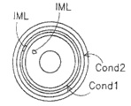
Fig. 6 a shows the part leak detection system of the leakage that detects immersion fluid.Described leak detection system comprises the first conductor COND1 and the second conductor COND2.The first and second conductor COND1, COND2 insulate relative to each other.Like this, between them, there is not or do not have substantially conductivity.Two conductor arrangement are at the potential leaking area of fluid feed system.Fig. 6 a for example can be understood as the top view of fluid feed system, and in this case, the container of maintenance immersion liquid will be positioned to conductor COND1, COND2 concentric, and be centered on by conductor.Leak from container and contact in the situation of conductor (example of the drop of immersion liquid IML has been shown among Fig. 6 a) at immersion liquid, because the existence of immersion liquid, the electric capacity between conductor COND1, the COND2 will change owing to the dielectric property of immersion liquid IML.Described leak detection system can be configured to measure the electric capacity between conductor COND1, the COND2 of mutually insulated.Use the benefit of capacitance leakage detecting device to be, it can carry out contactless measurement, do not electrically contact because need between conductor COND1, COND2 and immersion liquid, not set up, and when adopting conventional leakage detector, just need to set up to electrically contact, described conventional leakage detector has used resistance leakage detector (it can measure the resistance between first and second conductors like this, therefore needs the electrical connection between each conductor and the immersion liquid).Owing to avoided electrically contacting, so can avoid immersion liquid being polluted because of conductor or electrolytic effect.Another benefit of capacitance leakage detecting device is, it can implement detecting device fast, because it has omitted parasitic wave filter, described parasitic wave filter can be in the resistance leakage detector by immersion liquid and one or more stray capacitance in conjunction with and the resistance that constitutes and forming.The sensing circuit of the electric capacity that is made of two conductor COND1, COND2 for example can use the known sensing circuit that is used for capacitive transducer of trsanscondutance amplifier or other itself.Electric conductor COND1, COND2 can be by nonconducting layer of coverings substantially, described layer for example comprises plastics, therefore electrically contact so that avoid between conductor COND1, COND2 and (leakage) immersion liquid, forming, and avoid the electrolysis of immersion liquid and/or pollute because of conductor makes immersion liquid.
Shown in Fig. 6 a, two conductor COND1, COND2 comprise two concentric ring-shaped conductors.As mentioned above, conductor arrangement is at the end face of liquid-supplying system, thus in the face of the downstream lens of optical projection system, but except or replace conductor at end face, also possible is the bottom surface of conductor arrangement at liquid-supplying system, thus in the face of the base station of maintenance substrate.In first kind of situation, can detect the leakage that takes place at the top of liquid-supplying system, and in second kind of situation, can detect the leakage that takes place in the bottom of liquid-supplying system, i.e. the leakage of the generation of the gap between liquid-supplying system and substrate or the base station.
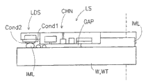
Fig. 6 b shows the more detailed embodiment of part, and it has shown the side sectional view that keeps the partially liq feed system LS of immersion liquid IML.In order to prevent that immersion liquid IML from entering clearance G AP, a plurality of channel C HN can be provided, be used to siphon away immersion liquid and/or be used to provide air-flow to prevent leakage of immersion liquid or the like.If however some immersion liquid IML are still arranged through channel C HN, leak detection system LDS will detect the capacitance variations between conductor COND1, the COND2 that the drop because of immersion liquid IML causes so, shown in Fig. 6 b.Should be noted that Fig. 6 b does not show that in the identical ratio of Fig. 6 a Fig. 6 b looks like the synoptic diagram of the detailed amplification of Fig. 6 a.
In the document, mention the place of term " liquid-supplying system ", also can think fluid feed system, perhaps opposite.In addition, should note, be made of mirror unit (one or more sides of this mirror unit are as the catoptron of interferometer IF1, IF2) in the embodiment of reality as the base station WT that identifies in the document, the worktable that is used for substrate can be positioned at this mirror unit.
In addition, should notice that Fig. 1-6 (partly) shows sectional view as understood by one of ordinary skill in the art.
Two or more embodiment shown in Fig. 2-6 can be incorporated in the single lithographic equipment, but in scope of the present invention, also can implement each embodiment individually.
Although in this application can be specifically with reference to using this lithographic equipment to make IC, but should be appreciated that lithographic equipment described herein may have other application, for example, it can be used for the guiding of making integrated optics system, being used for magnetic domain memory and check pattern, flat-panel monitor, LCD (LCD), thin-film head or the like.It should be appreciated by those skilled in the art that in this interchangeable purposes scope, the use of any here term " wafer " or " tube core " should think respectively can with more common term " substrate " or " target portion " synonym.Before or after exposure, can in for example coating and developing apparatus (usually resist layer being put in the substrate and a kind of instrument of the resist that will expose development), metering outfit and/or the instruments of inspection, handle the substrate of mentioning here.In applicable place, disclosure herein can be applicable to this and other base treatment instruments.In addition, for example, can repeatedly handle, so the terminology used here substrate also can refer to comprise the substrate of a plurality of layers of having handled substrate in order to form multilayer IC.
Although in the above can be specifically with reference in the application's optical lithographic methods process, using embodiments of the invention, but should be appreciated that the present invention can be used for other application, method for imprint lithography for example, the place in that the application allows the invention is not restricted to optical lithographic methods.In method for imprint lithography, the profile in the patterning device defines the pattern that forms in substrate.The profile of patterning device can also be expressed to and put in the suprabasil resist layer, and by the combination that applies electromagnetic radiation, heat, pressure or aforesaid way resist is solidified in substrate.After resist solidifies, patterning device can be shifted out from resist and stay pattern.
Term used herein " radiation " and " light beam " comprise all types of electromagnetic radiation, comprise that ultraviolet (UV) radiation (for example has about 365,248,193,157 or the wavelength of 126nm) and extreme ultraviolet (EUV) radiation (for example having the wavelength in the 5-20nm scope), and the particle beams, for example ion beam or electron beam.
Any one various types of optics or its combination can be represented in the term " lens " that this application is used, and comprises refractive optical components, reflection optics, magneto-optical parts, electromagnetism optics and electrostatic optics parts.
Although specific embodiments of the invention described above should be appreciated that to be different from described enforcement the present invention.For example, the present invention can take the form of computer program, this computer program comprise one or more sequences description above the machine readable instructions of disclosed method, perhaps comprise the data storage medium (for example semiconductor memory, disk or CD) that wherein stores this computer program.
Above description be in order to illustrate, rather than restriction.Therefore, it will be apparent to those skilled in the art that under the condition of the scope that does not break away from the claim that describes below, can carry out various modifications described invention.
Claims (19)
1. lithographic equipment comprises:
Be configured to keep the base station of substrate;
Measure the base station position measuring system of the position quantity of base station;
Be configured to patterned radiation laser beam is projected to optical projection system in the base target portion;
Immersion liquid is provided to the downstream lens of optical projection system and the fluid feed system in the space between the substrate;
Measure the fluid feed system position measuring system of the position quantity of fluid feed system; And
Prevent fluid feed system and keep the damage control system of the collision between the base station of substrate, described damage control system comprises the counter according to the size quantity in the gap between the base station of the position quantity Fluid Computation feed system of the position quantity of base station and fluid feed system and maintenance substrate, and should damage control system generation alerting signal when size quantity surpasses the predetermined safe level;
Wherein damage control system and comprise the correcting mechanism of calibrating gap size, when fluid feed system contact portion base station, the spacing between described correcting mechanism calibration base station and the fluid feed system.
2. lithographic equipment as claimed in claim 1, wherein the position quantity of fluid feed system comprises that the position of rotation of focal plane of the relative optical projection system of fluid feed system and fluid feed system are along substantially perpendicular to the position of the axis of the focal plane of optical projection system.
3. lithographic equipment as claimed in claim 2, the size quantity of its intermediate gap comprises the base station that keeps substrate and the local minimum spacing between the fluid feed system, counter is configured to according to separately position of rotation of fluid feed system and the base station that keeps substrate, is the position of rotation of the focal plane of relative optical projection system, and according to separately position of fluid feed system and the base station that keeps substrate, promptly local minimum spacing is determined perpendicular to the position of the axis of the focal plane of optical projection system substantially in the edge.
4. lithographic equipment as claimed in claim 1, wherein the position quantity of base station comprises the position of base station and the height map of the substrate that kept by base station, the size quantity of its intermediate gap comprises the base station that keeps substrate and the spacing between the fluid feed system, and described counter is according to the position of base station, the height map of substrate and the described spacing of position calculation of fluid feed system.
5. the speed that lithographic equipment as claimed in claim 1, the size quantity of its intermediate gap comprise fluid feed system and keep the spacing between the base station of substrate to change.
6. lithographic equipment as claimed in claim 1, wherein the position quantity of fluid feed system comprise fluid feed system relative to the rotational speed of the focal plane of optical projection system and fluid feed system along the speed that moves perpendicular to the axis of the focal plane of optical projection system substantially.
7. lithographic equipment as claimed in claim 6, the size quantity of its intermediate gap comprises the base station that keeps substrate and the pace of change of the local minimum spacing between the fluid feed system, described counter is configured to according to separately rotational speed of fluid feed system and the base station that keeps substrate, is the rotational speed of the focal plane of relative optical projection system, and according to separately speed of fluid feed system and the base station that keeps substrate, promptly the pace of change of local minimum spacing is determined on the edge substantially perpendicular to the speed of the axis of the focal plane of optical projection system.
8. lithographic equipment as claimed in claim 1, wherein the position quantity of base station comprises the speed of base station and the height map of the substrate that kept by base station, the size quantity of its intermediate gap comprises the base station that keeps substrate and the pace of change of the spacing between the fluid feed system, and described counter is according to the position of base station, the height map of substrate and the described pace of change of position calculation of fluid feed system.
9. lithographic equipment as claimed in claim 1, wherein the fluid feed system surface of faces substrate platform is limited by the sloping edge of fluid feed system.
10. lithographic equipment as claimed in claim 9, wherein the gradient of the sloping edge of fluid feed system is along being 1 at least 10 perpendicular to the direction on fluid feed system surface with ratio along the direction on the fluid feed system surface that is parallel to the faces substrate platform.
11. lithographic equipment as claimed in claim 1 wherein limits in the face of the surface of the base station structure of the fluid feed system sloping edge by the base station structure in operation.
12. lithographic equipment as claimed in claim 11, wherein the gradient of the sloping edge of base station structure be along perpendicular to the direction of base station body structure surface be 1 at least 10 along the ratio that is parallel to the direction of base station body structure surface.
13. lithographic equipment as claimed in claim 1, wherein the surface of the surface of fluid feed system and base station all comprises having the material of same rigidity substantially.
14. lithographic equipment as claimed in claim 1, wherein the part base station comprises the closed disk in the suitable dimple that is arranged in base station.
15. lithographic equipment as claimed in claim 1 wherein damages control system and is configured to according to the alerting signal that produces, and cuts off the power supply of the actuator of location fluid feed system.
16. lithographic equipment as claimed in claim 15, wherein the positioning system of fluid feed system comprises gravity compensator, be used to the power of affording redress with the gravity of compensating action on fluid feed system, described balancing force is overdimensioned, with provide act on the fluid feed system and the propelling fluid feed system away from the composite force that makes progress of base station.
17. lithographic equipment as claimed in claim 15, wherein fluid feed system comprises fluid-encapsulated substantially feed system and keeps the air knife in the gap between the base station of substrate, the air-flow of air knife be used to provide act on the fluid feed system and the propelling fluid feed system away from the power of base station.
18. a lithographic equipment comprises:
Be configured to keep the base station of substrate;
Be configured to patterned radiation laser beam is projected to optical projection system in the base target portion;
Immersion fluid is provided to the downstream lens of optical projection system and the fluid feed system in the space between the substrate;
The fluid feed system position control system of the position of control fluid feed system; And
Prevent fluid feed system and keep the damage control system of the collision between the base station of substrate, described damage control system compares the actuator driving signal and the reservation threshold of the actuator of drive fluid feed system position control system, described actuator is used to change the position of fluid feed system, thereby produces alerting signal when actuator driving signal surpasses threshold values;
Wherein damage control system and comprise the correcting mechanism of calibrating gap size, when fluid feed system contact portion base station, the spacing between described correcting mechanism calibration base station and the fluid feed system.
19. lithographic equipment as claimed in claim 18, wherein fluid feed system comprises fluid-encapsulated substantially feed system and keeps the air knife in the gap between the base station of substrate, the air-flow of air knife be used to provide act on the fluid feed system and the propelling fluid feed system away from the power of base station.
Applications Claiming Priority (2)
| Application Number | Priority Date | Filing Date | Title |
|---|---|---|---|
| US11/169298 | 2005-06-29 | ||
| US11/169,298 US7170583B2 (en) | 2005-06-29 | 2005-06-29 | Lithographic apparatus immersion damage control |
Related Child Applications (1)
| Application Number | Title | Priority Date | Filing Date |
|---|---|---|---|
| CN2008101833144A Division CN101424884B (en) | 2005-06-29 | 2006-06-28 | Lithographic apparatus immersion damage control |
Publications (2)
| Publication Number | Publication Date |
|---|---|
| CN1892435A CN1892435A (en) | 2007-01-10 |
| CN1892435B true CN1892435B (en) | 2010-06-09 |
Family
ID=37052587
Family Applications (2)
| Application Number | Title | Priority Date | Filing Date |
|---|---|---|---|
| CN2006100996802A Active CN1892435B (en) | 2005-06-29 | 2006-06-28 | Lithographic apparatus immersion damage control |
| CN2008101833144A Active CN101424884B (en) | 2005-06-29 | 2006-06-28 | Lithographic apparatus immersion damage control |
Family Applications After (1)
| Application Number | Title | Priority Date | Filing Date |
|---|---|---|---|
| CN2008101833144A Active CN101424884B (en) | 2005-06-29 | 2006-06-28 | Lithographic apparatus immersion damage control |
Country Status (7)
| Country | Link |
|---|---|
| US (1) | US7170583B2 (en) |
| EP (2) | EP1962140B1 (en) |
| JP (1) | JP4610526B2 (en) |
| KR (2) | KR100794688B1 (en) |
| CN (2) | CN1892435B (en) |
| SG (1) | SG128650A1 (en) |
| TW (1) | TWI338818B (en) |
Families Citing this family (14)
| Publication number | Priority date | Publication date | Assignee | Title |
|---|---|---|---|---|
| US7291569B2 (en) * | 2005-06-29 | 2007-11-06 | Infineon Technologies Ag | Fluids for immersion lithography systems |
| SG151198A1 (en) * | 2007-09-27 | 2009-04-30 | Asml Netherlands Bv | Methods relating to immersion lithography and an immersion lithographic apparatus |
| NL1036009A1 (en) * | 2007-10-05 | 2009-04-07 | Asml Netherlands Bv | An Immersion Lithography Apparatus. |
| JP2009094254A (en) * | 2007-10-05 | 2009-04-30 | Canon Inc | Immersion exposure apparatus and device manufacturing method |
| NL1036069A1 (en) * | 2007-10-30 | 2009-05-07 | Asml Netherlands Bv | An Immersion Lithography Apparatus. |
| NL1036579A1 (en) * | 2008-02-19 | 2009-08-20 | Asml Netherlands Bv | Lithographic apparatus and methods. |
| NL2007279A (en) * | 2010-09-28 | 2012-03-29 | Asml Netherlands Bv | Method for calibrating a target surface of a position measurement system, position measurement system, and lithographic apparatus. |
| NL2009692A (en) * | 2011-12-07 | 2013-06-10 | Asml Netherlands Bv | A lithographic apparatus and a device manufacturing method. |
| CN105739245B (en) * | 2014-12-12 | 2018-12-14 | 上海微电子装备(集团)股份有限公司 | A kind of immersion lithographic machine submergence unit collision prevention device and method |
| US10471610B2 (en) | 2015-06-16 | 2019-11-12 | Samsung Electronics Co., Ltd. | Robot arm having weight compensation mechanism |
| JP7015147B2 (en) * | 2017-11-06 | 2022-02-02 | キヤノン株式会社 | Imprinting equipment and article manufacturing method |
| CN110609448B (en) * | 2018-06-14 | 2020-12-01 | 上海微电子装备(集团)股份有限公司 | Silicon chip edge protection device |
| US11131931B2 (en) * | 2018-06-29 | 2021-09-28 | Taiwan Semiconductor Manufacturing Co., Ltd. | Fluidic leakage handling for semiconductor apparatus |
| JP7471171B2 (en) | 2020-08-17 | 2024-04-19 | 東京エレクトロン株式会社 | Substrate Processing Equipment |
Citations (4)
| Publication number | Priority date | Publication date | Assignee | Title |
|---|---|---|---|---|
| EP1420299A2 (en) * | 2002-11-12 | 2004-05-19 | ASML Netherlands B.V. | Immersion lithographic apparatus and device manufacturing method |
| EP1477856A1 (en) * | 2003-05-13 | 2004-11-17 | ASML Netherlands B.V. | Lithographic apparatus and device manufacturing method |
| CN1550905A (en) * | 2003-05-13 | 2004-12-01 | Asml荷兰有限公司 | Lithographic apparatus and device manufacturing method |
| EP1486828A2 (en) * | 2003-06-09 | 2004-12-15 | ASML Netherlands B.V. | Lithographic apparatus and device manufacturing method |
Family Cites Families (20)
| Publication number | Priority date | Publication date | Assignee | Title |
|---|---|---|---|---|
| US4509852A (en) | 1980-10-06 | 1985-04-09 | Werner Tabarelli | Apparatus for the photolithographic manufacture of integrated circuit elements |
| US4918977A (en) * | 1986-09-30 | 1990-04-24 | Tatsuta Electric Wire And Cable Co., Ltd. | Liquid leakage detector line |
| US5177996A (en) * | 1991-11-21 | 1993-01-12 | W. L. Gore & Associates, Inc. | Liquid leak detection cable |
| CN2212779Y (en) * | 1994-12-09 | 1995-11-15 | 水利部能源部地质勘探机电研究所 | Liquid level sensor |
| US5825483A (en) * | 1995-12-19 | 1998-10-20 | Cognex Corporation | Multiple field of view calibration plate having a reqular array of features for use in semiconductor manufacturing |
| JPH09248725A (en) * | 1996-03-13 | 1997-09-22 | Nikon Corp | Stage device |
| JP3526174B2 (en) * | 1997-04-14 | 2004-05-10 | キヤノン株式会社 | Semiconductor exposure apparatus and device manufacturing method |
| AU2747999A (en) | 1998-03-26 | 1999-10-18 | Nikon Corporation | Projection exposure method and system |
| JP2000076707A (en) * | 1998-08-31 | 2000-03-14 | Sony Corp | Master disk recording device for manufacture of optical recording medium |
| EP1037117A3 (en) | 1999-03-08 | 2003-11-12 | ASML Netherlands B.V. | Off-axis levelling in lithographic projection apparatus |
| JP2002280282A (en) * | 2001-03-16 | 2002-09-27 | Union Optical Co Ltd | Method and device for calibrating wafer |
| KR100588124B1 (en) * | 2002-11-12 | 2006-06-09 | 에이에스엠엘 네델란즈 비.브이. | Lithographic Apparatus and Device Manufacturing Method |
| JP3977324B2 (en) * | 2002-11-12 | 2007-09-19 | エーエスエムエル ネザーランズ ビー.ブイ. | Lithographic apparatus |
| EP1420300B1 (en) | 2002-11-12 | 2015-07-29 | ASML Netherlands B.V. | Lithographic apparatus and device manufacturing method |
| TW200500813A (en) * | 2003-02-26 | 2005-01-01 | Nikon Corp | Exposure apparatus and method, and method of producing device |
| US7779781B2 (en) * | 2003-07-31 | 2010-08-24 | Asml Netherlands B.V. | Lithographic apparatus and device manufacturing method |
| KR101613384B1 (en) * | 2003-08-21 | 2016-04-18 | 가부시키가이샤 니콘 | Exposure apparatus, exposure method, and device producing method |
| TWI361450B (en) * | 2003-10-31 | 2012-04-01 | Nikon Corp | Platen, stage device, exposure device and exposure method |
| US7057702B2 (en) * | 2004-06-23 | 2006-06-06 | Asml Netherlands B.V. | Lithographic apparatus and device manufacturing method |
| US7330238B2 (en) * | 2005-03-28 | 2008-02-12 | Asml Netherlands, B.V. | Lithographic apparatus, immersion projection apparatus and device manufacturing method |
-
2005
- 2005-06-29 US US11/169,298 patent/US7170583B2/en active Active
-
2006
- 2006-06-16 TW TW095121789A patent/TWI338818B/en active
- 2006-06-19 EP EP08075552.3A patent/EP1962140B1/en not_active Not-in-force
- 2006-06-19 EP EP06076267A patent/EP1739489B1/en not_active Not-in-force
- 2006-06-27 SG SG200604388A patent/SG128650A1/en unknown
- 2006-06-28 CN CN2006100996802A patent/CN1892435B/en active Active
- 2006-06-28 JP JP2006177816A patent/JP4610526B2/en active Active
- 2006-06-28 KR KR1020060058867A patent/KR100794688B1/en active IP Right Grant
- 2006-06-28 CN CN2008101833144A patent/CN101424884B/en active Active
-
2007
- 2007-08-10 KR KR1020070080482A patent/KR100775542B1/en active IP Right Grant
Patent Citations (4)
| Publication number | Priority date | Publication date | Assignee | Title |
|---|---|---|---|---|
| EP1420299A2 (en) * | 2002-11-12 | 2004-05-19 | ASML Netherlands B.V. | Immersion lithographic apparatus and device manufacturing method |
| EP1477856A1 (en) * | 2003-05-13 | 2004-11-17 | ASML Netherlands B.V. | Lithographic apparatus and device manufacturing method |
| CN1550905A (en) * | 2003-05-13 | 2004-12-01 | Asml荷兰有限公司 | Lithographic apparatus and device manufacturing method |
| EP1486828A2 (en) * | 2003-06-09 | 2004-12-15 | ASML Netherlands B.V. | Lithographic apparatus and device manufacturing method |
Also Published As
| Publication number | Publication date |
|---|---|
| EP1962140A3 (en) | 2010-07-28 |
| KR100794688B1 (en) | 2008-01-14 |
| KR20070087543A (en) | 2007-08-28 |
| US7170583B2 (en) | 2007-01-30 |
| CN1892435A (en) | 2007-01-10 |
| CN101424884B (en) | 2011-06-01 |
| EP1962140A2 (en) | 2008-08-27 |
| TW200712786A (en) | 2007-04-01 |
| EP1739489A2 (en) | 2007-01-03 |
| EP1739489A3 (en) | 2007-06-06 |
| EP1739489B1 (en) | 2011-05-11 |
| KR100775542B1 (en) | 2007-11-09 |
| SG128650A1 (en) | 2007-01-30 |
| US20070002294A1 (en) | 2007-01-04 |
| KR20070001829A (en) | 2007-01-04 |
| JP2007013159A (en) | 2007-01-18 |
| TWI338818B (en) | 2011-03-11 |
| EP1962140B1 (en) | 2013-07-31 |
| CN101424884A (en) | 2009-05-06 |
| JP4610526B2 (en) | 2011-01-12 |
Similar Documents
| Publication | Publication Date | Title |
|---|---|---|
| CN1892435B (en) | Lithographic apparatus immersion damage control | |
| US10739684B2 (en) | Lithographic apparatus and device manufacturing method | |
| TWI443478B (en) | Lithographic apparatus and device manufacturing method | |
| KR100742765B1 (en) | Lithographic apparatus and device manufacturing method | |
| US7619207B2 (en) | Lithographic apparatus and device manufacturing method | |
| US7462429B2 (en) | Method and arrangement for correcting thermally-induced field deformations of a lithographically exposed substrate | |
| JP2006332656A (en) | Dual stage lithographic device and method of manufacturing the device | |
| CN101038443B (en) | Lithographic apparatus, control system and device manufacturing method | |
| US8218128B2 (en) | Lithographic apparatus and device manufacturing method incorporating a pressure shield | |
| US20180095369A1 (en) | Lithographic apparatus and lithographic projection method | |
| KR20120069571A (en) | Method of updating calibration data and a device manufacturing method | |
| US8068210B2 (en) | Lithographic apparatus, device manufacturing method and computer program product | |
| JP2008072100A (en) | Lithography equipment and device manufacturing method | |
| JP4271692B2 (en) | Lithographic apparatus and method for calibrating such an apparatus | |
| WO2018215140A1 (en) | Setpoint generator, lithographic apparatus, lithographic apparatus operating method, and device manufacturing method |
Legal Events
| Date | Code | Title | Description |
|---|---|---|---|
| C06 | Publication | ||
| PB01 | Publication | ||
| C10 | Entry into substantive examination | ||
| SE01 | Entry into force of request for substantive examination | ||
| C14 | Grant of patent or utility model | ||
| GR01 | Patent grant |