CN1868086A - Enhanced fuel delivery for direct methanol fuel cells - Google Patents
Enhanced fuel delivery for direct methanol fuel cells Download PDFInfo
- Publication number
- CN1868086A CN1868086A CNA2004800299821A CN200480029982A CN1868086A CN 1868086 A CN1868086 A CN 1868086A CN A2004800299821 A CNA2004800299821 A CN A2004800299821A CN 200480029982 A CN200480029982 A CN 200480029982A CN 1868086 A CN1868086 A CN 1868086A
- Authority
- CN
- China
- Prior art keywords
- fuel
- container
- cassette
- fuel cassette
- shell
- Prior art date
- Legal status (The legal status is an assumption and is not a legal conclusion. Google has not performed a legal analysis and makes no representation as to the accuracy of the status listed.)
- Pending
Links
Images


Classifications
-
- H—ELECTRICITY
- H01—ELECTRIC ELEMENTS
- H01M—PROCESSES OR MEANS, e.g. BATTERIES, FOR THE DIRECT CONVERSION OF CHEMICAL ENERGY INTO ELECTRICAL ENERGY
- H01M8/00—Fuel cells; Manufacture thereof
- H01M8/04—Auxiliary arrangements, e.g. for control of pressure or for circulation of fluids
- H01M8/04082—Arrangements for control of reactant parameters, e.g. pressure or concentration
- H01M8/04201—Reactant storage and supply, e.g. means for feeding, pipes
- H01M8/04208—Cartridges, cryogenic media or cryogenic reservoirs
-
- H—ELECTRICITY
- H01—ELECTRIC ELEMENTS
- H01M—PROCESSES OR MEANS, e.g. BATTERIES, FOR THE DIRECT CONVERSION OF CHEMICAL ENERGY INTO ELECTRICAL ENERGY
- H01M8/00—Fuel cells; Manufacture thereof
- H01M8/10—Fuel cells with solid electrolytes
- H01M8/1009—Fuel cells with solid electrolytes with one of the reactants being liquid, solid or liquid-charged
- H01M8/1011—Direct alcohol fuel cells [DAFC], e.g. direct methanol fuel cells [DMFC]
-
- Y—GENERAL TAGGING OF NEW TECHNOLOGICAL DEVELOPMENTS; GENERAL TAGGING OF CROSS-SECTIONAL TECHNOLOGIES SPANNING OVER SEVERAL SECTIONS OF THE IPC; TECHNICAL SUBJECTS COVERED BY FORMER USPC CROSS-REFERENCE ART COLLECTIONS [XRACs] AND DIGESTS
- Y02—TECHNOLOGIES OR APPLICATIONS FOR MITIGATION OR ADAPTATION AGAINST CLIMATE CHANGE
- Y02E—REDUCTION OF GREENHOUSE GAS [GHG] EMISSIONS, RELATED TO ENERGY GENERATION, TRANSMISSION OR DISTRIBUTION
- Y02E60/00—Enabling technologies; Technologies with a potential or indirect contribution to GHG emissions mitigation
- Y02E60/30—Hydrogen technology
- Y02E60/50—Fuel cells
Landscapes
- Life Sciences & Earth Sciences (AREA)
- Engineering & Computer Science (AREA)
- Manufacturing & Machinery (AREA)
- Sustainable Development (AREA)
- Sustainable Energy (AREA)
- Chemical & Material Sciences (AREA)
- Chemical Kinetics & Catalysis (AREA)
- Electrochemistry (AREA)
- General Chemical & Material Sciences (AREA)
- Fuel Cell (AREA)
Abstract
An arrangement for a direct methanol fuel cell includes a fuel cartridge that supplies a source of fuel to the direct methanol fuel cell. The fuel cartridge has a surface area enhanced planar vaporization membrane residing in the fuel cartridge. The arrangement also includes a fuel reservoir that receives fuel from the fuel cartridge, the fuel reservoir arranged to deliver fuel to the fuel cell. The fuel reservoir also including a surface area enhanced planar vaporization membrane residing in the fuel reservoir. The combination of the surface area enhanced planar vaporization membranes residing in the fuel cartridge and reservoir provides a dual stage vaporization of fuel to the fuel cell. Other features included are passive or active arrangements to increase the temperature of the fuel or reduce pressure in the fuel container to enhance rate of vaporization.
Description
The present invention relates to the power supply of mobile electronic device.
Mobile electronic device is supplied with power with primary cell or rechargeable battery usually.The growth in mobile electronic device market and the variation of occupation mode provide rechargable power supplies to supply with the chance of power to electronic device.Although primary cell has bigger energy density, its internal resistance is bigger, and primary cell is not suitable for the electronic device of high flow rate so.Rechargeable battery can be handled big load, but does not have the energy capacity for the abundance of many application.
The interior fuel cell of power supply that is incorporated into portable device is hopeful to have the operating time longer than the battery system of routine, and this is owing to can use the fuel of energy capacity to cause.For the commercialization in portable power is used, developing several fuel cell technologies at present, for example direct methanol fuel cell (DMFC) and hydrogen polymer dielectric film (PEM) fuel cell.
In DMFC, fuel is methyl alcohol or water and methanol mixture.Methyl alcohol or carbinol mixture are transported in the anode chamber among the DMFC with liquid form, become the part of electricity in the oxidized electrochemical conversion that acts as a fuel of this methyl alcohol.Operation challenge in the DMFC system is " methanol crossover (crossover) ", a kind of methanol concentration of about 3% that wherein in anode chamber, is higher than, be that polymer dielectric film is passed in unacceptable high carbinol content migration, and not only cause parasitic loss (reducing the operating time), cause phenomenon again, thereby cause the power output of reduction in the mixed potential difference at negative pole place.
The positive pole of room temperature vapor phase delivery of methanol to fuel cell proposed.In this method, the ventilated membrane of passivation is parallel to the interior anodal layer of fuel cell and places with anodal ply, at room temperature liquid methanol is changed into methanol steam.Provide liquid methanol by fuel reservoir or fuel cassette (fuelcartridge).This method provides a kind of directapath that methyl alcohol is transported to fuel cell system.Being fed to the water that the pure methanol steam of anode chamber passes PEM with back-diffusion dilutes on the spot.
Some embodiments are disclosed to improve with the speed of vapor form transfer the fuel to fuel cell.Reinforcing membrane is arranged in fuel cassette or the fuel reservoir, offers fuel-cell fuel with vapor form.The speed that fuel is carried is directly proportional with the surface area of film.By compact fuel reservoir or fuel cartridge systems is provided, can under fair speed, provide the vapor phase delivery of methanol fuel, so that the DMFC system of higher-wattage becomes possibility.
According to an aspect of the present invention, provide the container of fuel supplying source in the direct methanol fuel cell.This container comprises shell, and wherein this shell has the shell wall that at least a portion is made up of Heat Conduction Material, the planar vaporization membrane of fuel outlet end of being supported by shell and the surface area increase that is positioned at this container.
Other embodiment within the scope of the claims.This container has the planar vaporization membrane (it is a polymer film) that surface area increases.This container has at least a portion shell wall of being made up of metal.The remainder of this chamber wall is adiabatic.At least a portion wall of forming by Heat Conduction Material that this container has that fuel outlet end with container is adjacent to arrange.This container can be a fuel cassette, and described fuel cassette contains liquid source of hydrogen.This liquid source of hydrogen is a methyl alcohol.Fuel container is a fuel reservoir.Fuel cassette has the shell wall that at least a portion is made up of Heat Conduction Material, and it improves the transporting velocity that the methyl alcohol in the vapor phase passes film, so that at outlet of container end delivering vapor.
According to additional aspect of the present invention, the fuel cassette of fuel supplying source in the direct methanol fuel cell comprises shell, and this shell contains liquid source of hydrogen and has shell wall that at least a portion is made up of Heat Conduction Material and by the fuel outlet end of shell support.
Other embodiment within the scope of the claims.Fuel cassette contains methyl alcohol.The remainder of cartridge wall is a heat-insulating material.Fuel cassette has the shell wall that at least a portion is made up of Heat Conduction Material, and it is the shell of tank part that the fuel outlet end with fuel cassette is adjacent to arrange.This part shell wall can be made up of metal.
According to additional aspect of the present invention, a kind of method of the present invention is included in the interior fuel arranged box of compartment of electronic device, so that the shell wall of the fuel cassette that a part is made up of Heat Conduction Material, arrange with the heat production assembly heat intercommunication ground in the electronic device, so that the vapor phase of fuel in the enclosure can be discharged from this fuel cassette.
This method make can be under the situation that does not need pump or other active control unit operation of fuel cells, with maintain anodal in low methanol activity.This method also makes it possible to the high speed delivering vapor, and makes that therefore the DMFC system higher than the method power of prior art becomes possibility for concrete battery size and geometry.
In accompanying drawing and following explanation, provided the details of one or more embodiments of the present invention.According to following explanation, accompanying drawing and claim, other features, objects and advantages of the present invention will become apparent.
Figure 1A and 1B describe the block diagram of supplying with the electronic device of power by fuel cell.
Fig. 2 A-2E is the schematic diagram that is described in fuel cassette interpolymer film device.
Fig. 3 is a schematic diagram of describing the fuel cassette with area heating installation.
Fig. 4 is a schematic diagram of describing the prismatic fuel cartridge with bladder (bladder) and area heating installation.
Fig. 4 A describes the schematic diagram of fuel cassette with the feature of valve.
Fig. 5-the 7th describes the various schematic representation of apparatus that cause steam pressure difference in the fuel cassette.
Fig. 8 describes the power device in the fuel cassette and the schematic diagram of CONSTRUCTED SPECIFICATION.
Fig. 9 is that methanol steam is pressed the chart that variations in temperature is done.
With reference to Figure 1A, show the electronic device 10 (hereinafter referred to as device 10) that portable power drives.Device 10 comprises the shell (not shown) with compartment (not shown) to hold the energy, and for example fuel cassette 12.Device 10 also comprises connectors 16, and it connects fuel cassette 12 and fuel cell 18 with steam rather than liquid form fuel supplying source (methyl alcohol or contain the solution of methyl alcohol and/or the mixture of carbon compound or this compound, to carry the hydrogen of certain form).Fuel cassette 12 comprises film, is typically expressed as 44, and its liquid phase with fuel separates with the vapor phase that can be transported to the outlet of fuel cassette 12 and enter in the fuel cell 18.The embodiment of film 44 has been described in figure below 2A-2E.Although described fuel cassette, comprise other embodiment of fuel container, for example the reservoir shown in Figure 1B 13.In this case, fuel reservoir 13 comprises film 44, and arrange described fuel reservoir 13, so that or acceptance is from the fuel of the fuel cassette 12 with film 44, perhaps pass through directly from the liquid fuel of fuel cassette 12 or by revocable fuels sources, for example pass through pouring liquid fuel in reservoir 13, replenish.
In some embodiments, fuel cell 18 is direct methanol fuel cell (DMFC).Randomly, connectors 16 connects or battery supply, for example primary cell or secondary cell, for example rechargeable battery (not shown) or fuel cassette 12.This connectors 16 can be distinguished fuel cassette and battery, and the technology of providing convenience allows therein in the interim unavailable place of fuel cassette, and fuel cell is supplied with the device of power and operated under the power of battery.Device 10 can be the portable device of any kind.Limiting examples comprises mobile phone, portable computer or audio/video device.
With reference to figure 2A-2C, fuel cassette 12 has the fuel delivery interface complementary with connectors 16 (Fig. 1), the port of export 32 shown in it comprises.Fuel cassette 12 comprises the planar vaporization membrane 44 that is positioned at the surface area increase of fuel cassette 12 by use, improves the device of steam-like fuel to the transporting velocity of fuel cell, and wherein said fuel cassette 12 fuel supplying are in direct methanol fuel cell (DMFC).
Shown in Fig. 2 A-2C, the fuel cassette outlet can be the port of export.The advantage that outlet is narrowed down is that fuel cassette 12 can be more suitable for extra function, for example is inserted into easily in the device or therefrom to take out, and not remarkable loss fuel.Another advantage of narrow opening is to adopt narrow outlet (as described below) to control optional thermal resistance more subtly.For example also can optionally using, the constriction device further limits mobile.
The other method that arrives the port of export is to separate the open cavity of fuel cassette 12 and fuel cell anode (not shown).The open cavity outlet can limit diffusion of vapor to anodal sharply, and this will take place when adopting narrow outlet.The open cavity outlet may be much the same wide with fuel cassette 12, so that allow the positive pole of maximum delivery to DMFC.Therefore, fuel cassette 12 can have interim cover layer or analog covers opening, and in use is removed.In some embodiments, fuel cassette 12 can have a part of film 44 of arranging across fuel cassette 12 inner openings.In general, preferred big opening,
Can make film 44 by many polymeric materials, comprising polyurethane, siloxanes, poly-(trimethyl silyl propine) and other material.The manufacturing of polymer can comprise introduces microporosity (microporosity) with (by evaporation mechanism) control evaporation process, or introduces fine and close membrane structure.Film also can be by the sheet metal manufacturing with polymer-coated or uncoated sintering, to realize similar volatility.
Fig. 2 A-2E shows and improves the also planar vaporization membrane 44 of the different table area increase of steady fuel transporting velocity, and the polymer film 46 that its major part that is included in the inner periphery of fuel cassette 12 is arranged is to provide the film of high surface.Fig. 2 B shows the composite membrane of being made up of multilayer or stacking polymer film 48, to increase the surface area of water vapour penetration.Can a series of lamination form alignment films 50, shown in Fig. 2 C.Fig. 2 D and 2E show another technology, and wherein polymer film 52 has macroscopic view irregular (as shown in) or microcosmic (not shown) rough textured film surface is used for evaporation to increase effective film surface area.
With reference to figure 2A, show ventilated membrane 46.Ventilated membrane 46 separates the fluid supply 62 of methyl alcohol and the vapor phase 64 of methyl alcohol.Steam occupies the interstitial volume between the inwall of film 46 and fuel cassette 12.With different at the film of the port of export 42 places use plane geometric shape, selective membrane 46 is so that surround volume of fuel and arrange in the inner periphery of the wall 65 of fuel cassette 12, thereby make the area of film to increase, and raising vapor phase methyl alcohol arrive the transporting velocity of the port of export 42 to adapt to the given fuel cassette or the size of fuel reservoir.The speed that fuel is carried is directly proportional with the surface area of planar film 46.Film 46 increases the transporting velocity of vapor phase fuel, and can use with rule or compact fuel reservoir or fuel cartridge systems, arrives at a high speed on the device that high-power DMFC supplies with power so that methanol fuel steam to be provided.
With reference to figure 2B, multilayer film 48 is included in the series of layers 48a of arranged around of fuel cassette 12 or stacked polymer film, to increase the surface area of film.Comprise the evaporating film 48a on the first surface of the substrate 48b that is arranged in porous material as an example of the multilayer film 48 of coiling battery forms, described substrate 48b holds liquid alcohol in the hole of this material, make liquid methanol can move to film 48a and change into vapor phase.Can make film by one of various polymeric systems, comprising polyurethane, siloxanes, poly-(trimethyl silyl propine) and other polymer composition, comprising composite material.The manufacturing of polymer can comprise introduces microporosity with (by evaporation mechanism) control evaporation process, or introduces fine and close membrane structure.
Film 48 also can be by with polymer-coated or uncoated sintered metal sheet manufacturing, to realize similar volatility.Substrate 48a is made by one of various polymeric systems, comprising the composite material of polyethylene, polypropylene, nylon, polyurethane or other similar polymer or one or more these polymer.Substrate 48a also can be made by the metal mold (form) with polymer-coated or uncoated sintering, to realize similar performance.
In some embodiments, the material of substrate 48a can have further amount " spongy " material.The apparent surface of sponge material 46b is coated with the impermeable material 48c of methyl alcohol, the impermeable material 48c of described methyl alcohol can be by such as cross-linked rubber, polymer/inorganic composite material, surface-treated material, for example the made of the high density polyethylene (HDPE) of surface fluorination or the impermeable material of other methyl alcohol and so on.
Can reel these three layers and arrange 48a-48c and be placed in the hydrostatic column that contains fuel cassette 12, wherein the row gap between evaporating film 48a and the impermeable layer of methyl alcohol 48c provides the path of carrying the high flux methanol steam to arrive anode chamber in fuel cell.This multilayer film 48 can provide very high-throughout methanol steam from the fuel reservoir or the fuel cassette 12 of relative compact.These three layers arrange 48a-48c also can be arranged as a series of plane layers and be arranged in different shape and the shell of various structures in, for example in the battery of prism shape in the outlet end office of shell, in the arranged around of shell, as shown in Figure 4, or the like.
The coiling cell apparatus (Fig. 2 B) and the rectangle of high surface, various middle arrangement that centers between the film (Fig. 2 A) of liquid fuel is possible.For example, shown in Fig. 2 C in the middle of fine and close stacked film 50, but the low membrane volume of high flux that obtains in the balance sandwich construction and selection (that is, high fuel energy density) (Fig. 2 A).Ventilated membrane 50 will extend between the inwall of fuel cassette 12, thereby the steam chambers 51 adjacent with the port of export 32 of fuel cassette 12 is provided.
With reference to figure 2D, 2E, the other method that the polymer film 52 that speed improves is provided is by providing at random or the roughening film surface (Fig. 2 E) of composition.Ventilated membrane 52 is arranged between the inwall of fuel cassette 12 and the steam chambers 51 adjacent with the port of export 32 of fuel cassette 12 is provided.Can on one or two surface of film, carry out roughening.One side of film (steam side usually) can limit seepage velocity.The preferred seepage velocity constrained side that increases film.
Although during the passivation ventilated membrane that uses the anodal layer be parallel in the fuel cell and place with anodal ply, for low-power (<3W) DMFC system, room temperature vapor phase delivery of methanol can work well to the positive pole of fuel cell, but this method can not provide the methanol steam flux of abundance to keep higher power operation.This is because due to the basic limitation in the evaporation technology that film is realized.For the positive pole of similar area, the methyl alcohol flux of unit are film is enough to maintain oxidization of methanol under the suitable speed.Yet when being higher than several watts power bracket, the area of film needs big unreasonably increase, guarantees that to keep fuel cell operates required methyl alcohol flux under higher-wattage.For the operation of higher-wattage, provide the fuel cassette of the required physical dimension of planar film area to be not convenient for consumer's use.In addition, big film possibility mechanical instability, and, have higher mechanical breakdown possibility along with time lapse.Depend on the selection of operating point and membrane material, for example the power bracket of 1W can require 0.7cm
2Membrane area, and 5 watts application can require 3.3cm
2Membrane area.At 3.3cm
2Relative superiority or inferiority more, this is not actual for many consumer applications, this is because it requires very large film surface area.
By being arranged in the heat-resistant element in the fuel cassette or can being used in combination with said method by the localized heating of utilizing the heat that generates by electronic device.
Above-described method causes on fixing geometric area usually the increase of (with therefore total water vapour penetration speed) of the effective surface area of film device 44.Be arranged in the speed of reinforcing membrane 44 in fuel cassette or the fuel reservoir, the fuel conveying that arrives fuel cell with vapor form is provided to be directly proportional with the increase surface area of film.The film that increases surface area makes can carry the methanol fuel vapor phase to become possibility with the compact fuel reservoir or the fuel cassette of the DMFC system that can operate higher-wattage under fair speed.This method also is convenient to do not having pump or other that operation of fuel cells under situation of source control device is arranged, with maintain anodal in low methanol activity.
With reference to figure 3, heat-resistant element 72 is arranged in vaporization membrane interface 44 places, improving the conveying of vapor fuel, as shown in.Evaporation rate increases along with temperature increases significantly.Evaporating film device shown in Fig. 2 A-2D can use heating element 72 as local thermal source, to increase temperature and therefore to increase evaporation rate.Heating element shown in Figure 3 72 and elementary load (device 10) layouts of switch on concurrently, and export supply power by the electricity of fraction fuel cell, so that the net increase of power output to be provided.
An example of heating element 72 is wire rods, for example has the coil of relative high resistance feature.Typical resistance characteristic scope as the heating element 72 of wire rod is 10-1M Ω/cm.Heating element 72 can be by high-resistance relatively material, and for example tungsten is formed.Spendable other material comprises nickel/evanohm and other material.High-resistance material usable polymers or noble metal coating prevent corrosion and pollution feul battery so that protection to be provided.Resistive element 72 is arranged with one of evaporating film 44 devices (for example, any one embodiment among Fig. 2 A-2E, or other structure) heat intercommunication ground.
With reference to figure 4, other method 80 can be under the situation that does not need film, fully by the liquid fuel of thermal process evaporation in fuel cassette 12, for example methyl alcohol.In this device, from the fuel cell (not shown), draw power, perhaps by be positioned at fuel cassette 12 with or on little battery 82 (for example, button cell) power is provided, supply with heater 84 power.This wire-form of sentencing the port of export 32 that is arranged in fuel cassette 12 illustrates the heater 84 that is not connected on the battery 10.
Fuel cassette 12 comprises wall or main body, be called prismatic battery housing 86 herein, it comprises heating element 84 and the impermeable material of fuel, the inner fuel bladder 90 of rubber and analog for example, and described bladder 90 contacts with the movably wall or the piston 88 of fuel cassette 12 inside.Spring 89 applies force on the wall.Can use the guider (not shown), when it when the length direction of prismatic can moves, guiding walls or piston 88.Liquid fuel, for example methyl alcohol is arranged in the bladder 90.When liquid consumed from fuel cassette 12, the pressure in bladder 90 descended, thereby made the power that produces by spring 89 head on bladder 90 promotion wall or pistons 88, was transported to the port of export 32 of fuel cassette 12 to guarantee the methyl alcohol in bladder 90.Wall/piston 88 and spring 89 guarantee evenly to transport the liquid from bladder 90, and irrelevant with the orientation of housing.
The port of export 32 can have and the incorporate fuel valve of evaporation heating unit.An embodiment shown in Fig. 4 A comprises heat-resistant element, and it is arranged in the interior finite region of valve member (not shown).In some embodiments, can save heating element 84.Can perhaps pass through the outside lead (not shown) by fuel cell power source by button cell inner at fuel cassette or that on fuel cassette, support, obtain to be used for the power of resistance heater.Other embodiment is possible.
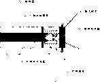
With reference to figure 4A, show an example of fuel valve 70 with integrated evaporation heating unit.For the embodiment of the fuel cassette shown in Figure 4 12 that comprises film device 46, show fuel valve 70 to export 32 form.Outlet 32 is described to have the valve 33 of integrated heating element 73.Valve 33 is supported on the cartridge wall 65, and comprises heating element 73, and described heating element 73 is arranged in various structures any, for example be arranged in the valve intracardiac, as shown in, perhaps arrange around the sidewall (not shown) of valve, perhaps integrated with the sidewall (not shown).Arrange heating element passes film 46 with increase evaporation rate.Valve can have various devices, so that in use be fixed on the device, as bayonet coupling, be threaded or the like.
With reference to figure 5, the device for substituting that improves the steam conveying is decompression to be provided on infiltration (steam) side of evaporating film 44 and to utilize pressure drop (being similar to temperature increases) can make the principle of liquid boiling or evaporation.Different is the vapour concentration of downstream decompression incrementally reduction fuel, thereby the actuating force of increase fuel from the liquid infiltration to the vapor phase.
A kind of device that causes decompression is the volume that is increased in the steam side 90 of fuel cassette 12.The steam side of fuel cassette 12 comprises the piston 92 of vapor permeable, wherein by the one or more spring assemblies 94 between the interior zone that is arranged in piston 92 and the fuel cassette 12 adjacent, head on the piston 92 that liquid 96 in the fuel cassette 12 promote described vapor permeable with the port of export 32 of fuel cassette 12.An embodiment of piston 92 is the same with evaporating film 44.The micropore of gauze or rigidity or macroporous layer are mechanically supported flexible evaporation layer (for example fluorocarbon polymer, polyethylene, polypropylene, Merlon, polyimides, polysulfones, polythiaether, polyurethane, polyester, cellulose or paper).Annular piston 92 provides leakproof seal when cartridge wall is slided.The external diameter of annulus just is enclosed within the fuel cartridge diameter.In addition, this annulus and adjacent cartridge wall are penetrated in the steam side with minimum liquid flow preferably by anti-fuel and impermeable made of fuel or coating.This material or coating are fluoropolymers, for example polytetrafluoroethylene or the like.In addition, especially for annulus, the material of preferred enough rigidity to minimize the radial thickness of annulus, still provides mechanical stability simultaneously, thereby maximum unlapped membrane area is provided.
When liquid volume was depleted, the volume of steam side increased, this be because piston 92 further away from each other the port of export 32 advance, thereby make the volumetric expansion of the steam side of fuel cassette 12.Moreover evaporating film 44 contains the fuel that is in liquid phase, and only allows water vapour penetration to arrive in the steam side 90 in principle.Mechanism can be initiatively (for example, under the effect of the power of spring) or passive (for example, only liquid displacement under).Passive promotion depends on the low friction of annular piston.
With reference to figure 6, show fuel cell 18 with the form (single membrane electrode assembly) of fuel battery 100, described fuel battery 100 has positive pole 102 and the negative pole 103 that separates by dividing plate 105.Fuel battery 100 is adjacent to arrange with the steam side 90 of fuel cassette 12.Steam from fuel cassette 12 directly flow on the anode electrode 102 of fuel cell 18.
Can make the volumetric expansion that causes in the steam side 90 of fuel cassette 18 volume contraction greater than the liquid fuel phase that causes because of the volume additional expansion that allows steam chambers 74.
With reference to figure 7, show device 110, by the conveying that 74 extra volumes improve steam of vapor phase chamber is provided.Along with device 110 increases the effective volume of the steam chambers 74 of fuel cassettes 12, also increase of the steam side 90 of fuel cassette 12 (it comprises piston 92 and inner spring 94, with shown in Figure 5 the same).By arrange at the outer surface of fuel cassette 12 and with the exterior chamber 112 of steam inside chamber 74 steam intercommunications, provide steam chambers 74 extra volume.Exterior chamber 112 has the impermeable piston 114 of steam, it is by being arranged in the one or more external springs devices 116 between impermeable piston 114 of steam and the fuel cell 18 adjacent with the port of export 32 of fuel cassette 12, and the steam that head in the exterior chamber 112 in the fuel cassette 12 promote.When vapour pressure increased, the increase of vapour pressure caused that piston 114 moves in the mode that increases exterior chamber 114 volumes.
An embodiment of the impermeable piston 114 of steam is sealed solid materials or uses encapsulant, for example poly-fluoroolefins, fluoroelastomer and rubber, for example siloxanes, fluoro siloxanes, acrylonitrile-butadiene rubber, neoprene, natural rubber or polyurethane coated metal.Metallic core can be included in the annular piston, so that mechanical stiffness to be provided.Exterior chamber 114 can be fuel vapour, anode reaction product and the inflatable gas volume of inert gas (for example nitrogen) possibly.Preferred discharging and exterior chamber are 114 relative, and (that is, on the opposite side of annular piston) retraction volume is accumulated in internal chamber 114 internal pressures avoiding in external environment condition.
Adopting under the situation of spring independently, expansion can be irrelevant with exhausting of liquid, just as shown here.Perhaps, can connect outside annular piston by machinery (or optionally magnetic), under the situation that liquid exhausts, with moving and line slip of internal piston.In addition, can make the cavity moulding (for example taper) of steam side, the increase of volumetric expansion is provided when running out of gas with box lunch.The expansion of steam side has the shortcoming of the extra total volume of requirement really greater than liquid contraction.
In order to control the conveying of fuel, can (for example by partial compression or stretching) synthesize or processing film, so that have variable permeability at the diverse location place on surface.For example, if the uneven distribution of anodal fuel is provided, then can provide the permeability (with therefore variable fuel flux) of position changeable to reach uniform fuel distribution.
With reference to figure 8, show the electronic device 10 of the portable supply power shown in Figure 1A and the 1B, it has shell 11, holds the energy, the compartment 14 of one of for example above-described fuel cassette 12.Connectors 16 connects the fuel cassette 12 and fuel cell (not shown) with steam rather than liquid form fuel supplying source (hydrogen of certain form).Fuel cassette 12 comprises evaporating film 44, and its liquid phase with fuel separates with the vapor phase that can be transported to the outlet 32 of fuel cassette 12.In some embodiments of fuel cassette 12, the wall of fuel cassette 12 or at least a portion wall, for example 12a is by Heat Conduction Material, typically metal manufacturing.This embodiment of fuel cassette 12 uses the wall conduct of fuel cassette by little portable device, for example the fin of the heat of portable computer generation.Those parts at least of metal or conductive material or the fuel cassette made by conductive material and the radiating subassembly 19 heat intercommunications ground layout of device 10 inside.Fuel cassette and radiating subassembly 19, for example the CPU in the portable computer arranges contiguously, perhaps is arranged in the air-flow pattern relevant with employed mini-fan (not shown) in some portable power devices.
Take away heat the radiating subassembly 19 of fuel cassette 12 in electronic device 10.The heat conduction sidewall that heat passes fuel cassette 12 shifts, and increases when methanol steam pressure is provided in fuel cassette 12.The increase of vapour pressure makes the steam separator membrane 44 of flowing through than more quickly.This technology provides the fuel cassette 12 with passivation system, and increase and therefore more energy delivery that described fuel cassette 12 provides methanol steam to press arrive fuel cell.In addition, use fuel cassette 12 can significantly reduce the needs (and the energy consumption on this device) of cooling fan, improve device efficiency and increase operating time of device as fin.The definite structure of fuel cassette 12 can be dependent on the structure of device 10, whether heat and the fan that this device generated exists.
The structure of fuel cassette 12 can comprise metal or other Heat Conduction Material wall 12a, and it combines with all the other adiabatic wall 12b of fuel cassette 12b.Thermal source 19 in heat conducting wall 12a and the device is directly arranged contiguously or is arranged or be arranged near thermal source 19 at least and take away from thermal source 19 in the employed inlet air flow path (not shown) of heat.Perhaps, heat conduction can be the upper part of the fuel cassette 12 adjacent with fuel outlet end 32 and in general be in line with the steam chambers that provides in fuel cassette.In some embodiments, the shell of fuel cassette 12 can be made up of metal or other Heat Conduction Material fully.Fuel cassette can have different shape, comprising the prismatic type described in Fig. 1, the 2A-2D, cylinder type or the like.
With reference to figure 9, show the chart that variation that methanol steam presses is done variations in temperature.
Fuel cassette 12 especially can use with the electronic building brick that produces big calorimetric in operating process.Fuel cassette 12 has the feature that the heat of utilization in device generates the surface, and wherein said heat generates the surface and directly contacts placement with fuel cassette ideally.In some embodiments, fuel cassette can be configured to fuel reservoir and replenishing or alternative heat dissipation element on radiating element.The fuel cassette that contains methanol liquid plays the effect of the fin of vapor phase fuel delivery system and device 10.Therefore, serve as that the fuel cassette of fin is auxiliary takes away heat from device 10, the heat that is produced simultaneously increases the vapour pressure of methanol steam, and therefore increase can be by the fuel quantity of film surface transport to the evaporation of fuel cell.Fuel cassette can comprise that outside and/or internal fins transfer to the heat of methanol fuel with increase.
In prevapourising, when fuel is flowed through film, fuel vaporization, rather than before film, evaporate.Some embodiments of film can be considered the prevapourising film, and other can be regarded as evaporating film.For example, be direct evaporation technology not having under the situation of film or before film, directly heating (steam-water vapour penetration).
Method described in above Fig. 2 A-2E cause common film device 44 in the zone of fixing geometry effective surface area (with therefore, total water vapour penetration speed) increase.The reinforcing membrane 44 that is arranged in fuel cassette or the fuel reservoir provides fuel to be transported in the fuel cell with vapor form with the speed that is directly proportional with the surface area of the increase of film.The described device of Fig. 3-9 increases evaporation rate particularly well and increases the temperature of liquid fuel source.Increase the film of surface area and/or the fuel reservoir or the fuel cartridge systems of heating or the feasible compactness of pressure drop device and become possibility, described fuel reservoir or fuel cartridge systems can be carried the vapor phase of methanol fuel under higher speed, the feasible DMFC system that can operate higher-wattage.This method also makes can not need pump or other that operation of fuel cells under situation of source control device is arranged, with maintain anodal in low methanol activity.
Many embodiments of the present invention have been described.However, be appreciated that and under the situation that does not break away from spirit of the present invention and scope, make various modifications.For example, this device can be the fuel reservoir that can periodically pass through the permanent connection of filling device postcombustion, rather than removable fuel cassette.In addition, can use this fuel cassette to provide the vapor phase methanol fuel to arrive in the fuel cell module, described fuel cell module has the fuel reservoir of the permanent connection that contains second film system.In this system, the flux of the vapor phase methyl alcohol that arrives fuel cell is regulated on two stages of second film ground, compares with the method for evaporating in single stage, and its mode can provide more controlled steam to carry.Therefore this technology can be applicable to have fuel reservoir or the fuel cassette of removable fuel cell or the fuel cell module of these two of permanent connection.Therefore, other embodiment within the scope of the following claims.
Claims (17)
1. the container of fuel supplying source in the direct methanol fuel cell, this container comprises:
Shell, wherein this shell has the shell wall that at least a portion is made up of Heat Conduction Material;
Fuel outlet end by the shell support; With
Be positioned at the planar vaporization membrane of the surface area increase of this container.
2. the container of claim 1, wherein the planar vaporization membrane that increases of surface area is a polymer film.
3. the container of claim 1, wherein the shell wall be made up of Heat Conduction Material of at least a portion is made up of metal.
4. the container of claim 1, wherein the remainder of chamber wall is adiabatic.
5. the container of claim 1, wherein the shell wall be made up of Heat Conduction Material of at least a portion is a part of shell of the container that is adjacent to arrange of the fuel outlet end with container.
6. the container of claim 1, wherein container is a fuel cassette.
7. the container of claim 1, wherein fuel cassette contains liquid source of hydrogen.
8. the fuel cassette of claim 1, wherein liquid source of hydrogen is a methyl alcohol.
9. the fuel cassette of claim 1, wherein container is a fuel reservoir.
10. the fuel cassette of claim 1, wherein the shell wall be made up of Heat Conduction Material of at least a portion improves the transporting velocity that the methyl alcohol in the vapor phase passes film, so that at outlet of container end delivering vapor.
11. the fuel supplying source is to the interior fuel cassette of direct methanol fuel cell, it comprises:
Shell, this shell contain liquid source of hydrogen and have the shell wall that at least a portion is made up of Heat Conduction Material;
Fuel outlet end by the shell support.
12. the fuel cassette of claim 11, wherein liquid is methyl alcohol.
13. the fuel cassette of claim 11, wherein the remainder of cartridge wall is adiabatic.
14. the fuel cassette of claim 11, wherein the shell wall be made up of Heat Conduction Material of at least a portion is a part of shell of the container that is adjacent to arrange of the fuel outlet end with fuel cassette.
15. the fuel cassette of claim 11, wherein the shell wall be made up of Heat Conduction Material of at least a portion is made up of metal.
16. a method, this method comprises:
Fuel arranged box in the compartment of electronic device, so that the shell wall of the fuel cassette that a part is made up of Heat Conduction Material and the ground of the heat production assembly heat intercommunication in electronic device layout, so that the vapor phase of fuel in the enclosure can be from this fuel cassette discharge.
17. the method for claim 16, wherein fuel cassette contains oxidable fuels sources.
Applications Claiming Priority (2)
| Application Number | Priority Date | Filing Date | Title |
|---|---|---|---|
| US10/664,818 US7935457B2 (en) | 2003-09-16 | 2003-09-16 | Enhanced fuel delivery for direct methanol fuel cells |
| US10/664,818 | 2003-09-16 |
Publications (1)
| Publication Number | Publication Date |
|---|---|
| CN1868086A true CN1868086A (en) | 2006-11-22 |
Family
ID=34274638
Family Applications (1)
| Application Number | Title | Priority Date | Filing Date |
|---|---|---|---|
| CNA2004800299821A Pending CN1868086A (en) | 2003-09-16 | 2004-09-08 | Enhanced fuel delivery for direct methanol fuel cells |
Country Status (6)
| Country | Link |
|---|---|
| US (1) | US7935457B2 (en) |
| EP (1) | EP1668731A2 (en) |
| JP (1) | JP2007506251A (en) |
| CN (1) | CN1868086A (en) |
| BR (1) | BRPI0414414A (en) |
| WO (1) | WO2005034274A2 (en) |
Cited By (1)
| Publication number | Priority date | Publication date | Assignee | Title |
|---|---|---|---|---|
| CN102569947A (en) * | 2010-12-06 | 2012-07-11 | 捷讯研究有限公司 | Mobile electronic device having a fuel cell surrounded by a solid-state battery |
Families Citing this family (33)
| Publication number | Priority date | Publication date | Assignee | Title |
|---|---|---|---|---|
| US20060127711A1 (en) * | 2004-06-25 | 2006-06-15 | Ultracell Corporation, A California Corporation | Systems and methods for fuel cartridge distribution |
| EP1641671B1 (en) * | 2003-06-27 | 2015-06-24 | Portaclave LLP | Portable fuel cartridge for fuel cells |
| US8114554B2 (en) * | 2003-09-16 | 2012-02-14 | The Gillette Company—South Boston | Enhanced fuel delivery for direct methanol fuel cells |
| US8084166B2 (en) | 2003-09-16 | 2011-12-27 | The Gillette Company | Enhanced fuel delivery for direct methanol fuel cells |
| US7059582B2 (en) * | 2003-12-01 | 2006-06-13 | Societe Bic | Fuel cell supply having fuel compatible materials |
| US7117732B2 (en) * | 2003-12-01 | 2006-10-10 | Societe Bic | Fuel gauge for fuel cartridges |
| US7810669B2 (en) * | 2004-03-05 | 2010-10-12 | Airbus Deutschland Gmbh | Replaceable cartridge for liquid hydrogen |
| US20050202291A1 (en) * | 2004-03-09 | 2005-09-15 | Schweizer Patrick M. | Shutter mechanism for fuel cell |
| US7968250B2 (en) * | 2004-06-25 | 2011-06-28 | Ultracell Corporation | Fuel cartridge connectivity |
| US7648792B2 (en) * | 2004-06-25 | 2010-01-19 | Ultracell Corporation | Disposable component on a fuel cartridge and for use with a portable fuel cell system |
| JP2008506240A (en) * | 2004-07-08 | 2008-02-28 | ダイレクト メタノール ヒューエル セル コーポレイション | Fuel cell cartridge and fuel supply system |
| EP1830427B1 (en) * | 2004-11-19 | 2012-01-25 | Toyo Seikan Kaisha, Ltd. | Cartridge for methanol fuel cell |
| JP4696580B2 (en) | 2005-02-10 | 2011-06-08 | ソニー株式会社 | Electrochemical energy generating apparatus and method for driving the apparatus |
| EP1883128A4 (en) * | 2005-03-31 | 2011-06-29 | Toshiba Kk | Fuel cell |
| WO2006134975A1 (en) | 2005-06-17 | 2006-12-21 | Kabushiki Kaisha Toshiba | Fuel for fuel cell, fuel cartridge for fuel cell and fuel cell |
| US7779856B2 (en) * | 2005-10-05 | 2010-08-24 | Societe Bic | Fuel cartridge of a fuel cell with fuel stored outside fuel liner |
| US20080029156A1 (en) * | 2006-01-19 | 2008-02-07 | Rosal Manuel A D | Fuel cartridge |
| US20070231621A1 (en) * | 2006-01-19 | 2007-10-04 | Rosal Manuel A D | Fuel cartridge coupling valve |
| JP5105756B2 (en) * | 2006-03-10 | 2012-12-26 | 三洋電機株式会社 | Fuel cell |
| US7625649B1 (en) | 2006-05-25 | 2009-12-01 | University Of Connecticut | Vapor feed fuel cells with a passive thermal-fluids management system |
| JP5124990B2 (en) * | 2006-05-29 | 2013-01-23 | ソニー株式会社 | Reactant supply apparatus and reaction apparatus |
| JP5063935B2 (en) * | 2006-06-02 | 2012-10-31 | 東洋製罐株式会社 | Polyester container for fuel cell cartridges |
| JP5177343B2 (en) * | 2006-07-14 | 2013-04-03 | 栗田工業株式会社 | Solid methanol fuel cartridge for direct methanol fuel cell and direct methanol fuel cell system |
| US8656793B2 (en) | 2006-12-22 | 2014-02-25 | Societe Bic | State of charge indicator and methods related thereto |
| US8286464B2 (en) * | 2006-12-22 | 2012-10-16 | Societe Bic | Sensing device and methods related thereto |
| US8166833B2 (en) * | 2006-12-22 | 2012-05-01 | Socíété BIC | State of charge indicator and methods related thereto |
| US8142441B2 (en) * | 2008-10-16 | 2012-03-27 | Aesculap Implant Systems, Llc | Surgical instrument and method of use for inserting an implant between two bones |
| US8591587B2 (en) | 2007-10-30 | 2013-11-26 | Aesculap Implant Systems, Llc | Vertebral body replacement device and method for use to maintain a space between two vertebral bodies within a spine |
| US8142435B2 (en) * | 2009-02-19 | 2012-03-27 | Aesculap Implant Systems, Llc | Multi-functional surgical instrument and method of use for inserting an implant between two bones |
| US8685553B2 (en) * | 2010-12-06 | 2014-04-01 | Blackberry Limited | Mobile electronic device having a fuel cell surrounded by a solid-state battery |
| US9725316B2 (en) | 2013-03-07 | 2017-08-08 | Intelligent Energy Inc. | Hydrogen generator with replaceable fuel unit and a method of producing hydrogen gas |
| WO2014137340A1 (en) * | 2013-03-07 | 2014-09-12 | Intelligent Energy, Inc. | Hydrogen generator with replaceable fuel unit and a method of producing hydrogen gas |
| US10259700B2 (en) * | 2017-03-05 | 2019-04-16 | Motion Pro, Inc | Volatile liquids refueling apparatus |
Family Cites Families (21)
| Publication number | Priority date | Publication date | Assignee | Title |
|---|---|---|---|---|
| JPS5883765U (en) * | 1981-12-02 | 1983-06-07 | 日産自動車株式会社 | methanol fuel cell |
| JPH02234358A (en) * | 1989-03-07 | 1990-09-17 | Nippon Soken Inc | Fuel cell |
| DK0457921T3 (en) | 1989-12-12 | 1996-11-18 | Toray Industries | Hitherto platinum (II) complex and agent for the treatment of a malignant tumor |
| US5354474A (en) | 1989-12-22 | 1994-10-11 | The Dow Chemical Company | Dynamic membrane separation process for improved selectivity |
| JPH03229624A (en) * | 1990-02-02 | 1991-10-11 | Mitsubishi Rayon Co Ltd | Permselective membrane |
| US5069793A (en) | 1990-09-12 | 1991-12-03 | Membrane Technology & Research, Inc. | Membrane module |
| US5364711A (en) | 1992-04-01 | 1994-11-15 | Kabushiki Kaisha Toshiba | Fuel cell |
| ES2144873T3 (en) * | 1996-06-26 | 2000-06-16 | Siemens Ag | DIRECT METHANOL FUEL CELL (DMFC). |
| US5681467A (en) | 1996-09-19 | 1997-10-28 | The Dow Chemical Company | Method for forming a membrane into a predetermined shape |
| US5900330A (en) | 1997-09-25 | 1999-05-04 | Kagatani; Takeo | Power device |
| US6447941B1 (en) | 1998-09-30 | 2002-09-10 | Kabushiki Kaisha Toshiba | Fuel cell |
| AU2001250054A1 (en) * | 2000-03-30 | 2001-10-15 | Manhattan Scientifics, Inc. | Diffusion fuel ampoules for fuel cells |
| DE10035538A1 (en) | 2000-07-21 | 2002-02-07 | Bosch Gmbh Robert | sensor |
| GB2366070A (en) * | 2000-08-19 | 2002-02-27 | Adelan Ltd | Fuel cell operation |
| ATE400904T1 (en) * | 2001-06-01 | 2008-07-15 | Polyfuel Inc | INTERCHANGEABLE FUEL CARTRIDGE, FUEL CELL UNIT WITH SAID FUEL CARTRIDGE FOR PORTABLE ELECTRONIC DEVICES AND CORRESPONDING DEVICE |
| US6645651B2 (en) * | 2001-06-01 | 2003-11-11 | Robert G. Hockaday | Fuel generator with diffusion ampoules for fuel cells |
| JP4094265B2 (en) * | 2001-09-25 | 2008-06-04 | 株式会社日立製作所 | Fuel cell power generator and device using the same |
| EP1313160A1 (en) * | 2001-11-13 | 2003-05-21 | SFC Smart Fuel Cell AG | Device for supplying fuel to a fuel cell |
| US7037611B2 (en) * | 2003-04-11 | 2006-05-02 | Hewlett-Packard Development Company, L.P. | Fuel cartridge for use with fuel cell |
| US20040209133A1 (en) * | 2003-04-15 | 2004-10-21 | Hirsch Robert S. | Vapor feed fuel cell system with controllable fuel delivery |
| US20040253500A1 (en) * | 2003-06-13 | 2004-12-16 | Bourilkov Jordan T. | Fuel cartridge interconnect for portable fuel cells |
-
2003
- 2003-09-16 US US10/664,818 patent/US7935457B2/en not_active Expired - Fee Related
-
2004
- 2004-09-08 CN CNA2004800299821A patent/CN1868086A/en active Pending
- 2004-09-08 EP EP04783382A patent/EP1668731A2/en not_active Withdrawn
- 2004-09-08 WO PCT/US2004/029105 patent/WO2005034274A2/en active Application Filing
- 2004-09-08 JP JP2006526929A patent/JP2007506251A/en active Pending
- 2004-09-08 BR BRPI0414414-7A patent/BRPI0414414A/en not_active IP Right Cessation
Cited By (2)
| Publication number | Priority date | Publication date | Assignee | Title |
|---|---|---|---|---|
| CN102569947A (en) * | 2010-12-06 | 2012-07-11 | 捷讯研究有限公司 | Mobile electronic device having a fuel cell surrounded by a solid-state battery |
| CN102569947B (en) * | 2010-12-06 | 2015-10-14 | 黑莓有限公司 | Have by solid state battery around the mobile electronic device of fuel cell |
Also Published As
| Publication number | Publication date |
|---|---|
| BRPI0414414A (en) | 2006-11-14 |
| EP1668731A2 (en) | 2006-06-14 |
| US20050058879A1 (en) | 2005-03-17 |
| US7935457B2 (en) | 2011-05-03 |
| WO2005034274A2 (en) | 2005-04-14 |
| WO2005034274A3 (en) | 2005-11-17 |
| JP2007506251A (en) | 2007-03-15 |
Similar Documents
| Publication | Publication Date | Title |
|---|---|---|
| CN1868086A (en) | Enhanced fuel delivery for direct methanol fuel cells | |
| Li et al. | Review and advances of direct methanol fuel cells (DMFCs) part I: Design, fabrication, and testing with high concentration methanol solutions | |
| CN1868085A (en) | Enhanced fuel delivery for direct methanol fuel cells | |
| US7604673B2 (en) | Annular fuel processor and methods | |
| US7846593B2 (en) | Heat and water management device and method in fuel cells | |
| CN1243607A (en) | Surface replica fuel cell for micro fuel cell electrical power pack | |
| JP7361067B2 (en) | Fuel cell with modular base active area | |
| CN1868083A (en) | Enhanced fuel delivery for direct methanol fuel cells | |
| JP2008060044A (en) | Fuel cell system | |
| JP2007095541A (en) | Fuel cell | |
| JP2008146883A (en) | Fuel cell apparatus | |
| JP2007214097A (en) | Fuel cell stack | |
| JP4733514B2 (en) | Fuel supply device for direct liquid fuel cell | |
| CN1713432A (en) | Reformer and fuel cell system having the same | |
| JP2005347239A (en) | Capacitor integrated fuel cell | |
| JP2010251300A (en) | Fuel cell system | |
| JP3416578B2 (en) | Solid polymer electrolyte fuel cell | |
| US8460840B2 (en) | Separator for fuel cell and fuel cell comprising the same | |
| KR101107081B1 (en) | Stack for fuel cell and fuel cell system with the same | |
| JP5168861B2 (en) | Fuel cell | |
| KR100590010B1 (en) | Fuel cell system and stack of the same | |
| US8679692B2 (en) | Fuel cell having enhanced heat dissipation | |
| TW200818592A (en) | Fuel cell | |
| JP2007066755A (en) | Fuel cell module and fuel cell equipped with the fuel cell module | |
| JP2011222349A (en) | Fuel cell and fuel cell stack using the same |
Legal Events
| Date | Code | Title | Description |
|---|---|---|---|
| C06 | Publication | ||
| PB01 | Publication | ||
| C10 | Entry into substantive examination | ||
| SE01 | Entry into force of request for substantive examination | ||
| C02 | Deemed withdrawal of patent application after publication (patent law 2001) | ||
| WD01 | Invention patent application deemed withdrawn after publication |
Open date: 20061122 |