CN1840887A - Fuel jet device for internal combustion engine - Google Patents
Fuel jet device for internal combustion engine Download PDFInfo
- Publication number
- CN1840887A CN1840887A CNA2006100716587A CN200610071658A CN1840887A CN 1840887 A CN1840887 A CN 1840887A CN A2006100716587 A CNA2006100716587 A CN A2006100716587A CN 200610071658 A CN200610071658 A CN 200610071658A CN 1840887 A CN1840887 A CN 1840887A
- Authority
- CN
- China
- Prior art keywords
- control
- chamber
- fuel injection
- pump
- pressure
- Prior art date
- Legal status (The legal status is an assumption and is not a legal conclusion. Google has not performed a legal analysis and makes no representation as to the accuracy of the status listed.)
- Granted
Links
Images

Classifications
-
- F—MECHANICAL ENGINEERING; LIGHTING; HEATING; WEAPONS; BLASTING
- F02—COMBUSTION ENGINES; HOT-GAS OR COMBUSTION-PRODUCT ENGINE PLANTS
- F02M—SUPPLYING COMBUSTION ENGINES IN GENERAL WITH COMBUSTIBLE MIXTURES OR CONSTITUENTS THEREOF
- F02M57/00—Fuel-injectors combined or associated with other devices
- F02M57/02—Injectors structurally combined with fuel-injection pumps
- F02M57/022—Injectors structurally combined with fuel-injection pumps characterised by the pump drive
- F02M57/023—Injectors structurally combined with fuel-injection pumps characterised by the pump drive mechanical
-
- F—MECHANICAL ENGINEERING; LIGHTING; HEATING; WEAPONS; BLASTING
- F02—COMBUSTION ENGINES; HOT-GAS OR COMBUSTION-PRODUCT ENGINE PLANTS
- F02M—SUPPLYING COMBUSTION ENGINES IN GENERAL WITH COMBUSTIBLE MIXTURES OR CONSTITUENTS THEREOF
- F02M45/00—Fuel-injection apparatus characterised by having a cyclic delivery of specific time/pressure or time/quantity relationship
- F02M45/02—Fuel-injection apparatus characterised by having a cyclic delivery of specific time/pressure or time/quantity relationship with each cyclic delivery being separated into two or more parts
- F02M45/04—Fuel-injection apparatus characterised by having a cyclic delivery of specific time/pressure or time/quantity relationship with each cyclic delivery being separated into two or more parts with a small initial part, e.g. initial part for partial load and initial and main part for full load
- F02M45/06—Pumps peculiar thereto
-
- F—MECHANICAL ENGINEERING; LIGHTING; HEATING; WEAPONS; BLASTING
- F02—COMBUSTION ENGINES; HOT-GAS OR COMBUSTION-PRODUCT ENGINE PLANTS
- F02M—SUPPLYING COMBUSTION ENGINES IN GENERAL WITH COMBUSTIBLE MIXTURES OR CONSTITUENTS THEREOF
- F02M45/00—Fuel-injection apparatus characterised by having a cyclic delivery of specific time/pressure or time/quantity relationship
- F02M45/02—Fuel-injection apparatus characterised by having a cyclic delivery of specific time/pressure or time/quantity relationship with each cyclic delivery being separated into two or more parts
- F02M45/04—Fuel-injection apparatus characterised by having a cyclic delivery of specific time/pressure or time/quantity relationship with each cyclic delivery being separated into two or more parts with a small initial part, e.g. initial part for partial load and initial and main part for full load
- F02M45/08—Injectors peculiar thereto
-
- F—MECHANICAL ENGINEERING; LIGHTING; HEATING; WEAPONS; BLASTING
- F02—COMBUSTION ENGINES; HOT-GAS OR COMBUSTION-PRODUCT ENGINE PLANTS
- F02M—SUPPLYING COMBUSTION ENGINES IN GENERAL WITH COMBUSTIBLE MIXTURES OR CONSTITUENTS THEREOF
- F02M2200/00—Details of fuel-injection apparatus, not otherwise provided for
- F02M2200/09—Fuel-injection apparatus having means for reducing noise
-
- F—MECHANICAL ENGINEERING; LIGHTING; HEATING; WEAPONS; BLASTING
- F02—COMBUSTION ENGINES; HOT-GAS OR COMBUSTION-PRODUCT ENGINE PLANTS
- F02M—SUPPLYING COMBUSTION ENGINES IN GENERAL WITH COMBUSTIBLE MIXTURES OR CONSTITUENTS THEREOF
- F02M2200/00—Details of fuel-injection apparatus, not otherwise provided for
- F02M2200/31—Fuel-injection apparatus having hydraulic pressure fluctuations damping elements
- F02M2200/315—Fuel-injection apparatus having hydraulic pressure fluctuations damping elements for damping fuel pressure fluctuations
-
- F—MECHANICAL ENGINEERING; LIGHTING; HEATING; WEAPONS; BLASTING
- F02—COMBUSTION ENGINES; HOT-GAS OR COMBUSTION-PRODUCT ENGINE PLANTS
- F02M—SUPPLYING COMBUSTION ENGINES IN GENERAL WITH COMBUSTIBLE MIXTURES OR CONSTITUENTS THEREOF
- F02M59/00—Pumps specially adapted for fuel-injection and not provided for in groups F02M39/00 -F02M57/00, e.g. rotary cylinder-block type of pumps
- F02M59/20—Varying fuel delivery in quantity or timing
- F02M59/36—Varying fuel delivery in quantity or timing by variably-timed valves controlling fuel passages to pumping elements or overflow passages
- F02M59/366—Valves being actuated electrically
-
- F—MECHANICAL ENGINEERING; LIGHTING; HEATING; WEAPONS; BLASTING
- F02—COMBUSTION ENGINES; HOT-GAS OR COMBUSTION-PRODUCT ENGINE PLANTS
- F02M—SUPPLYING COMBUSTION ENGINES IN GENERAL WITH COMBUSTIBLE MIXTURES OR CONSTITUENTS THEREOF
- F02M61/00—Fuel-injectors not provided for in groups F02M39/00 - F02M57/00 or F02M67/00
- F02M61/16—Details not provided for in, or of interest apart from, the apparatus of groups F02M61/02 - F02M61/14
- F02M61/20—Closing valves mechanically, e.g. arrangements of springs or weights or permanent magnets; Damping of valve lift
- F02M61/205—Means specially adapted for varying the spring tension or assisting the spring force to close the injection-valve, e.g. with damping of valve lift
-
- F—MECHANICAL ENGINEERING; LIGHTING; HEATING; WEAPONS; BLASTING
- F02—COMBUSTION ENGINES; HOT-GAS OR COMBUSTION-PRODUCT ENGINE PLANTS
- F02M—SUPPLYING COMBUSTION ENGINES IN GENERAL WITH COMBUSTIBLE MIXTURES OR CONSTITUENTS THEREOF
- F02M63/00—Other fuel-injection apparatus having pertinent characteristics not provided for in groups F02M39/00 - F02M57/00 or F02M67/00; Details, component parts, or accessories of fuel-injection apparatus, not provided for in, or of interest apart from, the apparatus of groups F02M39/00 - F02M61/00 or F02M67/00; Combination of fuel pump with other devices, e.g. lubricating oil pump
- F02M63/0012—Valves
- F02M63/0014—Valves characterised by the valve actuating means
- F02M63/0015—Valves characterised by the valve actuating means electrical, e.g. using solenoid
-
- F—MECHANICAL ENGINEERING; LIGHTING; HEATING; WEAPONS; BLASTING
- F02—COMBUSTION ENGINES; HOT-GAS OR COMBUSTION-PRODUCT ENGINE PLANTS
- F02M—SUPPLYING COMBUSTION ENGINES IN GENERAL WITH COMBUSTIBLE MIXTURES OR CONSTITUENTS THEREOF
- F02M63/00—Other fuel-injection apparatus having pertinent characteristics not provided for in groups F02M39/00 - F02M57/00 or F02M67/00; Details, component parts, or accessories of fuel-injection apparatus, not provided for in, or of interest apart from, the apparatus of groups F02M39/00 - F02M61/00 or F02M67/00; Combination of fuel pump with other devices, e.g. lubricating oil pump
- F02M63/0012—Valves
- F02M63/0031—Valves characterized by the type of valves, e.g. special valve member details, valve seat details, valve housing details
- F02M63/0049—Combined valve units, e.g. for controlling pumping chamber and injection valve
Landscapes
- Engineering & Computer Science (AREA)
- Chemical & Material Sciences (AREA)
- Combustion & Propulsion (AREA)
- Mechanical Engineering (AREA)
- General Engineering & Computer Science (AREA)
- Fuel-Injection Apparatus (AREA)
Abstract
燃料喷射装置对于内燃机的每个缸具有一个燃料高压泵(10)及一个与该燃料高压泵连接的燃料喷射阀(12)。通过泵活塞(18)限定泵工作室的边界,该燃料喷射阀具有喷射阀元件,通过后者控制至少一个喷射孔。泵工作室与卸载区域的连接部分(62)至少间接通过电操作的控制阀控制,其中,设置可运动的控制活塞(50),它至少间接在闭合方向上作用在所述至少一个喷射阀元件上,其中控制活塞在其背对所述至少一个喷射阀元件的一侧至少间接由在泵工作室中的压力加载。控制活塞以其朝该喷射阀元件的一侧限定控制室(60)的边界。通到卸载区域的通过控制阀控制的连接部分(62)通到控制室中,控制室通过被节流的连接部分(64)至少间接与泵工作室连接。

The fuel injection device has a high-pressure fuel pump (10) for each cylinder of the internal combustion engine and a fuel injection valve (12) connected to the high-pressure fuel pump. A pump working chamber is delimited by a pump piston (18), and the fuel injection valve has an injection valve element via which at least one injection opening is actuated. The connection (62) of the pump working chamber to the unloading area is controlled at least indirectly via an electrically operated control valve, wherein a movable control piston (50) is provided which acts at least indirectly on the at least one injection valve element in the closing direction , wherein the control piston is acted on at least indirectly by the pressure in the pump working chamber on its side facing away from the at least one injection valve element. The control piston delimits the control chamber ( 60 ) with its side facing the injection valve element. A connection ( 62 ) to the unloading region, which is controlled by a control valve, leads into a control chamber, which is at least indirectly connected to the pump working chamber via a throttled connection ( 64 ).
Description
技术领域technical field
本发明涉及一种用于内燃机的燃料喷射装置。The invention relates to a fuel injection device for an internal combustion engine.
背景技术Background technique
已由DE 101 19 984 A公开了这样一个燃料喷射装置。这个燃料喷射装置对于内燃机的每个缸具有一个燃料高压泵及一个与该燃料高压泵连接的燃料喷射阀。该燃料高压泵具有一个至少间接地被内燃机驱动成往复运动的泵活塞,后者限定一个泵工作室的边界。该燃料喷射阀具有一个喷射阀元件,通过该喷射阀元件控制至少一个喷射孔。该喷射阀元件在一个打开方向上由在一个与该泵工作室相连接的压力室中具有的压力加载并且可抵抗一个闭合力在打开方向上运动以释放所述至少一个喷射孔。设置有一个电操作的控制阀,通过该控制阀至少间接地控制泵工作室与一个卸载区域的连接部分。此外设置有一个可运动的控制活塞,该控制活塞至少间接地在闭合方向上作用在该喷射阀元件上并且该控制活塞在它的背对该喷射阀元件的侧上由泵工作室中具有的压力加载。作用在该喷射阀元件上的闭合力通过一个闭合弹簧产生,其中该控制活塞作用在闭合弹簧的一个支承件上。在泵活塞的排流行程中,在一个确定的时刻该控制阀被关闭,使得该泵工作室与卸载区域被断开并且在该泵工作室中建立高压。在压力室中具有与泵工作室中相同的高压并且如果通过这个高压比通过该闭合弹簧施加一个更大的力到喷射阀元件上,则该喷射阀元件在打开方向上运动并且释放所述至少一个喷射孔,由此燃料被喷射。在进一步提高泵工作室中的压力的情况下,该控制活塞抵抗该闭合弹簧的力移动,直到该控制活塞靠置在一个止挡上,由此由该闭合弹簧施加到该喷射阀元件上的力被提高并且该喷射阀元件运动到它的闭合位置中,由此燃料喷射结束。在此情况下,在该燃料喷射期间只喷射一个小的燃料量作为预喷射。接着,泵工作室中的压力进一步上升并且如果通过该压力比通过闭合弹簧施加一个更大的力到该喷射阀元件上,则该喷射阀元件又在打开方向上运动并且释放所述至少一个喷射孔,由此燃料又被喷射。在此情况下,在该燃料喷射期间根据内燃机的需求喷射一个较大的燃料量作为主喷射。为了结束该主喷射,该控制阀被打开,使得该泵工作室与所述卸载区域相连接并且在该泵工作室中不再具有高压,其中该喷射阀元件通过该闭合弹簧运动到其闭合位置中并且该控制活塞又返回到其初始位置中。该预喷射,尤其是该预喷射的时刻及预喷射量,在这个料喷射装置中通过在结构上对该控制活塞、该控制活塞的可能的行程以及该闭合弹簧的设计来确定,由此该预喷射和相对于接着的主喷射的时间间隔以及开始主喷射时的压力不能灵活地根据内燃机的不同的运行工况被匹配。所公知的燃料喷射装置的缺点还在于,非常小的燃料喷射量的精确控制困难。此外,燃料喷射阀的关闭、即燃料喷射的结束在泵工作室中的压力低时才进行,由此使内燃机的有害物质排放提高。此外,在打开及关闭控制阀时所出现的大的压力梯度造成燃料喷射装置的高的噪声并且造成卸载区域中的显著的压力波动。Such a fuel injection device has been disclosed by DE 101 19 984 A. This fuel injection system has a high-pressure fuel pump for each cylinder of the internal combustion engine and a fuel injection valve connected to the high-pressure fuel pump. The high-pressure fuel pump has a pump piston driven to and fro at least indirectly by the internal combustion engine, which delimits a pump working chamber. The fuel injection valve has an injection valve element via which at least one injection opening is actuated. The injection valve element is acted upon in an opening direction by the pressure prevailing in a pressure chamber connected to the pump working chamber and is movable in the opening direction against a closing force in order to release the at least one injection opening. An electrically operated control valve is provided, via which the connection of the pump working chamber to a relief region is at least indirectly controlled. Furthermore, a movable control piston is provided, which acts at least indirectly on the injection valve element in the closing direction and which is controlled on its side facing away from the injection valve element by the pump working chamber. Pressure loaded. The closing force acting on the injection valve element is generated by a closing spring, wherein the control piston acts on a bearing of the closing spring. During the displacement stroke of the pump piston, the control valve is closed at a certain point in time, so that the pump working chamber is disconnected from the relief region and a high pressure builds up in the pump working chamber. There is the same high pressure in the pressure chamber as in the pump working chamber and if a greater force is exerted on the injection valve element by this high pressure than by the closing spring, the injection valve element moves in the opening direction and releases the at least An injection hole through which fuel is injected. When the pressure in the pump working chamber is further increased, the control piston moves against the force of the closing spring until the control piston rests against a stop, whereby the pressure exerted by the closing spring on the injection valve element The force is increased and the injection valve element is moved into its closed position, whereby fuel injection ends. In this case, only a small fuel quantity is injected as a pilot injection during this fuel injection. Subsequently, the pressure in the pump working chamber rises further and if a greater force is exerted on the injection valve element by the pressure than by the closing spring, the injection valve element moves in the opening direction again and releases the at least one injection valve. hole through which fuel is injected again. In this case, a larger fuel quantity is injected as the main injection during the fuel injection according to the requirements of the internal combustion engine. To end the main injection, the control valve is opened so that the pump working chamber is connected to the unloading region and there is no longer a high pressure in the pump working chamber, wherein the injection valve element is moved into its closed position by the closing spring and the control piston returns to its initial position. The pilot injection, in particular the timing and quantity of the pilot injection, is structurally determined in this material injection device by the design of the control piston, the possible stroke of the control piston and the closing spring, whereby the The time interval between the pilot injection and the subsequent main injection and the pressure at the start of the main injection cannot be flexibly adapted to the different operating conditions of the internal combustion engine. A further disadvantage of the known fuel injection devices is that precise control of very small fuel injection quantities is difficult. Furthermore, the closing of the fuel injection valve, ie the end of the fuel injection, takes place only when the pressure in the pump working chamber is low, thereby increasing the pollutant emissions of the internal combustion engine. Furthermore, the large pressure gradients that occur when opening and closing the control valve lead to high noise levels of the fuel injection system and to considerable pressure fluctuations in the unloading region.
发明内容Contents of the invention
根据本发明,提出了一种用于内燃机的燃料喷射装置,该燃料喷射装置对于该内燃机的每个缸具有一个燃料高压泵及一个与该燃料高压泵相连接的燃料喷射阀,其中该燃料高压泵具有一个至少间接地通过该内燃机驱动成往复运动的泵活塞,该泵活塞限定一个泵工作室的边界,其中该燃料喷射阀具有至少一个喷射阀元件,至少一个喷射孔被该喷射阀元件控制,该喷射阀元件由在该燃料喷射阀的一个与该泵工作室相连接的压力室中具有的压力在打开方向上加载并且可抵抗一个闭合力在打开方向上运动以释放所述至少一个喷射孔,该燃料喷射装装置还具有一个电操作的控制阀,通过该控制阀至少间接地控制该泵工作室与一个卸载区域的连接部分,其中,设置有一个可运动的控制活塞,该控制活塞至少间接地在闭合方向上作用在所述至少一个喷射阀元件上,其中该控制活塞在它的背对所述至少一个喷射阀元件的一侧至少间接地由在该泵工作室中具有的压力加载,其中:该控制活塞以它的朝着所述至少一个喷射阀元件的一侧限定一个控制室的边界,所述通过该控制阀控制的连接部分通到卸载区域;该控制室通过一个被节流的连接部分至少间接地与该泵工作室相连接。According to the invention, a fuel injection device for an internal combustion engine is proposed, which has a high-pressure fuel pump for each cylinder of the internal combustion engine and a fuel injection valve connected to the high-pressure fuel pump, wherein the high-pressure fuel The pump has a pump piston driven to and fro at least indirectly by the internal combustion engine, the pump piston delimiting a pump working chamber, wherein the fuel injection valve has at least one injection valve element by which at least one injection opening is controlled , the injection valve element is loaded in the opening direction by the pressure present in a pressure chamber of the fuel injection valve connected to the pump working chamber and is movable in the opening direction against a closing force to release the at least one injection orifice, the fuel injection device also has an electrically operated control valve via which the connection of the pump working chamber to an unloading area is at least indirectly controlled, wherein a movable control piston is provided, the control piston Acting at least indirectly on the at least one injection valve element in the closing direction, wherein the control piston is at least indirectly influenced by the pressure prevailing in the pump working chamber on its side facing away from the at least one injection valve element Loading, wherein: the control piston delimits a control chamber with its side facing the at least one injection valve element, the connection part controlled by the control valve leads to an unloading area; the control chamber is connected via a The throttle connection is at least indirectly connected to the pump working chamber.
相比之下,根据本发明的燃料喷射装置具有其的优点,即可以灵活地借助控制阀通过控制活塞控制预喷射的时刻及燃料喷射量。为了开始燃料喷射,该控制阀以公知的方式被关闭,使得在泵工作室中及在压力室中建立高压并且喷射阀元件通过该压力室中具有的压力抵抗该闭合力而打开。该控制活塞在此基本上是力平衡的,由此通过该控制活塞没有力作用在该喷射阀元件上。为了结束预喷射,该控制阀又被打开,其中泵工作室及压力室中的压力由于与控制室连接的连接部分中的节流部位而只是被滞后地降低,而控制室中的压力由于通到卸载区域的连接部分被打开而迅速下降,由此该喷射阀元件由于通过该控制活塞在闭合方向上作用在该喷射阀元件上的力而迅速地关闭。因此,在泵工作室中及在压力室中保持一个被提高的压力并且接着该控制阀为了主喷射又被关闭,使得在泵工作室中及在压力室中可以进行一个新的、迅速的压力上升并且该喷射阀元件又被打开。在这样的情况下,该主喷射开始的时刻及泵工作室中和压力室中的开始该主喷射时的压力可以灵活地通过该控制阀的控制来确定。为了结束该主喷射,该控制阀又被打开,其中泵工作室中及压力室中的压力再次只是被滞后地下降,由此该燃料喷射阀在泵工作室中及压力室中的压力高的情况下关闭,由此内燃机的有害物质排放减少。此外,由于所述泵工作室中及压力室中的被滞后的压力降低,仅仅得到很小的压力梯度,由此减小了燃料喷射装置的噪声并且仅仅引起卸载区域中的小的压力波动。最后,也可以控制燃料喷射的非常短暂的中断以及由此非常小的燃料喷射量。In contrast, the fuel injection system according to the invention has the advantage that the timing of the pre-injection and the fuel injection quantity can be flexibly controlled by means of the control valve via the control piston. To start fuel injection, the control valve is closed in a known manner, so that a high pressure builds up in the pump working chamber and in the pressure chamber and the injection valve element is opened against the closing force by the pressure present in the pressure chamber. The control piston is essentially force-balanced, so that no force acts on the injection valve element via the control piston. To end the pre-injection, the control valve is opened again, wherein the pressure in the pump working chamber and the pressure chamber is reduced only with a delay due to the throttle in the connection to the control chamber, while the pressure in the control chamber is reduced due to the flow through the control chamber. The connection to the unloading area is opened down rapidly, whereby the injection valve element is closed rapidly due to the force acting on the injection valve element in the closing direction by the control piston. Therefore, a raised pressure is maintained in the pump working chamber and in the pressure chamber and then the control valve is closed again for the main injection, so that a new, rapid pressure can take place in the pump working chamber and in the pressure chamber. rises and the injection valve element opens again. In such a case, the timing at which the main injection starts and the pressures in the pump working chamber and in the pressure chamber at the start of the main injection can be flexibly determined by the control of the control valve. To end the main injection, the control valve is opened again, wherein the pressure in the pump working chamber and in the pressure chamber is again reduced only with a delay, so that the fuel injector is at a higher pressure in the pump working chamber and in the pressure chamber In case of shutdown, the emission of harmful substances from the internal combustion engine is reduced. Furthermore, due to the retarded pressure drop in the pump working chamber and in the pressure chamber, only small pressure gradients result, thereby reducing the noise of the fuel injection system and causing only small pressure fluctuations in the relief region. Finally, very brief interruptions of the fuel injection and thus very small fuel injection quantities can also be controlled.
下述技术方案中说明了根据本发明的燃料喷射装置的有利的构型及进一步构型。Advantageous configurations and further developments of the fuel injection device according to the invention are described in the technical solutions below.
该控制室与该泵工作室的被节流的连接部分通过控制活塞中的至少一个通道构成,在所述通道中设置有一个节流部位。The throttled connection of the control chamber to the pump working chamber is formed by at least one channel in the control piston, in which channel a throttle point is arranged.
该控制室与该泵工作室的被节流的连接部分通过该控制活塞的圆周上的至少一个凹槽构成,在所述凹槽中设置有一个节流部位。The throttled connection of the control chamber to the pump working chamber is formed by at least one recess on the circumference of the control piston, in which recess a throttle point is arranged.
该控制室通过该被节流的连接部分同该泵工作室与该压力室之间的连接部分相连接。The control chamber is connected via the throttled connection to the connection between the pump working chamber and the pressure chamber.
由此分别可实现该控制室至少间接地与该泵工作室可简单建立地连接。In this way, a simple connectable connection of the control chamber at least indirectly to the pump working chamber can be achieved in each case.
该控制活塞的在离开所述至少一个喷射阀元件指向的方向上的行程通过一个止挡来限制。The travel of the control piston in the direction pointing away from the at least one injection valve element is limited by a stop.
该控制活塞被一个弹簧朝所述至少一个喷射阀元件加载。The control piston is biased against the at least one injection valve element by a spring.
由此分别保证,控制活塞在泵活塞的抽吸行程中不随该泵活塞一起运动。This ensures in each case that the control piston does not move with the pump piston during its suction stroke.
在所述通到卸载区域的连接部分中在该控制室与该控制阀之间设置有一个节流部位。A throttle is arranged between the control chamber and the control valve in the connection to the relief region.
由此可实现控制活塞的两侧的压力比及由此通过该控制活塞作用在该喷射阀元件上的力的协调。A coordination of the pressure ratio on both sides of the control piston and thus the force acting by the control piston on the injection valve element can thus be achieved.
该控制活塞通过一个压杆至少间接地支承在所述至少一个喷射阀元件上。The control piston is supported at least indirectly on the at least one injector element via a pressure rod.
作用在所述至少一个喷射阀元件上的闭合力由一个闭合弹簧产生;该控制活塞至少间接地作用在该闭合弹簧的一个支承体上。The closing force acting on the at least one injection valve element is generated by a closing spring; the control piston acts at least indirectly on a support body of the closing spring.
该控制活塞设置在所述至少一个喷射阀元件与该泵工作室之间。The control piston is arranged between the at least one injection valve element and the pump working chamber.
附图说明Description of drawings
附图中示出了本发明的多个实施例,在下面的说明中对它们进行详细地描述。附图表示:Several exemplary embodiments of the invention are shown in the drawings and are described in detail in the following description. The accompanying drawings indicate:
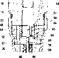
图1根据一个第一实施例的用于内燃机的燃料喷射装置的简化示意图,Figure 1 is a simplified schematic diagram of a fuel injection device for an internal combustion engine according to a first embodiment,
图2根据该第一实施例的燃料喷射装置的在图1中以II标示的局部的放大视图,以及FIG. 2 is an enlarged view of a part marked II in FIG. 1 of the fuel injection device according to the first embodiment, and
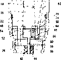
图3至6根据其它一些实施例的燃料喷射装置的局部II。3 to 6 are details II of a fuel injection device according to some other embodiments.
具体实施方式Detailed ways
图1中示出了根据一个第一实施例的用于内燃机的燃料喷射装置。该燃料喷射装置对于内燃机的每个缸各具有一个燃料高压泵10和一个与该燃料高压泵相连接的燃料喷射阀12。燃料高压泵10与燃料喷射阀12可以组合成一个结构单元,后者也被称作泵-喷嘴单元。但燃料高压泵10与燃料喷射阀12也可以构造成分开的结构单元,它们通过一个燃料导管互相连接。A fuel injection device for an internal combustion engine according to a first embodiment is shown in FIG. 1 . The fuel injection system has a high-pressure fuel pump 10 for each cylinder of the internal combustion engine and a fuel injection valve 12 connected to the high-pressure fuel pump. The high-pressure fuel pump 10 and the fuel injection valve 12 can be combined to form a structural unit, which is also referred to as a pump-nozzle unit. However, high-pressure fuel pump 10 and fuel injector 12 can also be constructed as separate structural units, which are connected to one another via a fuel line.
燃料高压泵10具有一个泵体14,在该泵体中一个泵活塞18在一个缸孔16中被密封地导向,该泵活塞由内燃机的凸轮轴的凸轮20抵抗一个复位弹簧19的力驱动成往复运动。泵活塞18在缸孔16中限定一个泵工作室22的边界,在该泵工作室中燃料在泵活塞18的排流行程中在高压下被压缩。通过凸轮20的轮廓来确定在泵活塞18的排流行程中泵工作室22中的压力变化。泵工作室22具有一个与一个卸载区域相连接的连接部分,该连接部分被一个电操作的控制阀23控制。因此,通过该控制阀23控制燃料喷射并且该控制阀可以具有一个电磁的或压电的执行机构。控制阀23被一个电子的控制装置25控制。该卸载区域例如是一个低压区域,在该低压区域中通过一个输送泵21来产生一个提高的压力,以便可在泵活塞18的抽吸行程中填充泵工作室22。该输送泵21从一个燃料储备容器24抽吸燃料。The high-pressure fuel pump 10 has a pump body 14, in which a
燃料喷射阀12具有一个阀体26,该阀体可构造成多件式的,并且该阀体与泵体14相连。在阀体26中,一个喷射阀元件28可以纵向移动地在一个孔30中被导向。该孔30相对于泵体14的缸16至少近似平行地延伸,但是也可以相对于该缸倾斜地延伸。阀体26在它的朝着内燃机的缸的燃烧室的端部区域上具有至少一个、优选多个喷射孔32。喷射阀元件28在它的朝着该燃烧室的端部区域上具有一个例如大致锥状的密封面34,后者与一个在阀体26中构造在该阀体的朝着该燃烧室的端部区域的、例如同样大致锥状的阀座36共同作用,所述喷射孔32从该阀座或在该阀座后通出。Fuel injector 12 has a
在阀体26中在喷射阀元件28与该孔30之间朝着阀座36具有一个环形室38,后者在它的背对该阀座36的端部区域中通过孔30的径向扩宽而过渡到一个围绕着喷射阀元件28的压力室40。喷射阀元件28在压力室40的高度上由于横截面减小而具有一个朝向阀座36的压力肩42。一个被预加载的闭合弹簧44作用在喷射阀元件28的背对该燃烧室的端部上,该喷射阀元件28被该闭合弹簧压向阀座36。该闭合弹簧44设置在一个弹簧保持体的通过一个孔构成的弹簧室46中,弹簧保持体构成阀体26的一部分并且该弹簧保持体连接在该孔30上。该压力室40具有一个延伸穿过阀体26及泵体14的、与泵工作室22相连接的连接部分48。该连接部分48在此例如通过一些设置在阀体26及泵体14中的孔来构成。Between the injection valve element 28 and the bore 30 in the
在图1及2中示出了根据一个第一实施例的燃料喷射装置,其中在泵工作室22与该弹簧室46之间设置有一个控制活塞50,后者在一个设置在阀体26与泵体14之间的中间体54的一个孔52中可移动地被导向。该孔52在此相对于孔30并且相对于缸孔16至少近似同轴地延伸。控制活塞50通过一个压杆56在喷射阀元件28的闭合方向上作用在该喷射阀元件上。该压杆56可与控制活塞50或与喷射阀元件28构造成单件式的,替换地也可以作为一个单独的部件与控制活塞50或喷射阀元件28连接或者作为单独的部件被夹紧在控制活塞50与喷射阀元件28之间。压杆56延伸穿过弹簧室46并且在中间体54中的一个孔58中被密封地导向。该压杆56的直径比该控制活塞50的直径小得多。控制活塞50朝泵工作室22的行程通过一个止挡51来限制。该止挡51例如可以通过泵体14上的一个环形肩构成,该环形肩被这样地构造,即缸孔16比孔52具有一个更小的直径,控制活塞50设置在该孔52中。1 and 2 show a fuel injection device according to a first embodiment, wherein a
控制活塞50在它的朝着泵工作室22的端面上由泵工作室22中具有的压力加载。可以这样设置,通过控制活塞50的端面来限定该泵工作室22的边界。控制活塞50在孔52中以该控制活塞的朝着喷射阀元件28的端面限定一个控制室60的边界。由控制阀23控制的通到卸载区域的连接部分62通到该控制室60中。该连接部分62例如通过一些延伸在中间体54及泵体14中的孔来构成。控制活塞50中具有至少一个通道、例如通孔64形式的通道,控制室60通过所述通道与泵工作室22相连接。在通道64中设置有一个节流部位65。在控制室60与所述卸载区域的由控制阀23控制的连接部分62中可优选也设置一个节流部位66。可替换地,控制活塞50上的所述通道也可以通过至少一个设置在该控制活塞的圆周上的凹槽67来构成,在该凹槽中设置有节流部位65。也可以设置多个在控制活塞50的圆周上分布地设置的凹槽67。也可将所述至少一个凹槽67设置在孔52的圆周中来代替设置在控制活塞50中。The
下面说明根据第一实施例的燃料喷射装置的功能。在泵活塞18的抽吸行程中——在该抽吸行程中该泵活塞通过复位弹簧19作用从缸孔16中运动出来,控制阀23被打开,使得由输送泵21输送的燃料经过连接部分62到达该控制室60中并且从该控制室通过通道64到达泵工作室22中。通过止挡51保证控制活塞50在泵活塞18的抽吸行程上不一起运动。在泵活塞18的排流行程中,该泵活塞通过凸轮20作用抵抗复位弹簧19的力运动到缸孔16中,其中控制阀23在排流行程开始时可以仍是打开的。在此情况下,燃料被该泵活塞18从泵工作室22又挤出到卸载区域中,其中由于设置在通道64中的节流部位65在泵工作室22及在压力室40中出现一个提高的压力并且在控制室60中由于连接部分62中的节流部位66也出现一个提高的压力。由于节流部位65上的节流及控制室60中的由此引起的压力下降,控制活塞50被保持靠置在喷射阀元件28上并且通过该控制活塞产生一个在闭合方向上作用在该喷射阀元件28上的小的力。连接部分62中的节流部位66也可被取消,其中因此该控制阀23优选只释放一个小的通到卸载区域的通流截面,该通流截面构成一个节流部位。控制阀23具有一个控制阀元件,后者在控制阀23转换时优选只进行一个小的行程,使得该转换可以非常迅速地进行。The function of the fuel injection device according to the first embodiment will be described below. During the suction stroke of the
根据内燃机的工作参数如尤其是该内燃机的转速及负载,控制阀23在一个确定的时刻由控制装置25关闭,以使得不再有燃料流出到该卸载区域中。于是通过该泵活塞18在泵工作室22中、在压力室40中以及在控制室60中产生高压。在控制室60中在此具有与泵工作室22中至少基本上相同的高压,由此通过控制活塞50至少基本上不产生在闭合方向上作用在该喷射阀元件28上的力。如果由压力室40中具有的高压通过压力肩42产生的力比闭合弹簧44的力更大,则喷射阀元件28以及该控制活塞50与该喷射阀元件一起在打开方向29上运动并且释放所述至少一个喷射孔32。即使在喷射阀元件28被打开时,压力室40与泵工作室22的连接部分48也通过控制活塞50不被关闭而是保持打开。在预喷射时喷射阀元件28在此仅仅对于一个短暂的时间并且为了喷射一个小的燃料量被打开。为了结束该预喷射,控制阀23被控制装置25打开,使得通到卸载区域的连接部分62被打开。在预喷射时所喷射的燃料量通过该预喷射的持续时间来确定。控制室60中的压力在此情况下比泵工作室22中及压力室40中的压力更迅速地下降,使得通过控制活塞50产生在闭合方向上作用在该喷射阀元件28上的力,喷射阀元件28通过该力在其闭合方向上运动。泵工作室22中及压力室40中的在控制阀23被打开时相对于控制室60被滞后的压力下降通过通道64中的节流部位65引起。泵工作室22及压力室40中的压力由于节流部位65而比卸载区域中的压力保持明显更高。即使在喷射阀元件28关闭并且控制活塞50靠置在该喷射阀元件上时,连接部分62通到控制室60的通入部位也通过控制活塞50不被关闭而是保持打开。Depending on the operating parameters of the internal combustion engine, such as in particular the rotational speed and the load of the internal combustion engine, the control valve 23 is closed by the control device 25 at a certain point in time, so that no fuel can flow out into the relief region. A high pressure is then generated by the
如果要开始一个接着的主喷射,则该控制阀23通过控制装置25又被关闭,使得控制室60中的压力又上升并且至少基本上不再产生在闭合方向上通过该控制阀50作用在喷射阀元件28上的力。该喷射阀元件28于是通过压力室40中具有的高压又打开并且释放所述至少一个喷射孔32。由于泵工作室22中及压力室40中获得的提高的压力,在关闭控制活塞23后为主喷射更迅速地建立高压。开始该主喷射的时刻和压力室40中的开始该主喷射时的压力可以通过该控制装置25根据内燃机的工作参数来灵活地确定。为了结束该主喷射,该控制阀23通过控制装置25又被打开,其中在主喷射时所喷射的燃料量通过控制阀23的闭合持续时间来确定。在结束该主喷射时在泵工作室22中也获得一个提高的高压,由该压力通过该控制活塞50来支持喷射阀元件28的关闭。通过所述由于控制活塞50而在泵工作室22中即使在控制阀23被打开时也获得的提高的压力,在卸载区域中造成相对小的压力波动。此外,压力梯度,即泵工作室22中的压力变化,在控制阀23打开及关闭后由于该控制活塞50而减小,由此内燃机用于泵活塞18的驱动负载减小。在主喷射后还可以进行燃料的后喷射,为此控制阀23被该控制装置25再次关闭。If a subsequent main injection is to be started, the control valve 23 is closed again by the control device 25, so that the pressure in the
图3中示出了根据一个第二实施例的燃料喷射装置的局部II,在该第二实施例中基本的结构与第一实施例中的相同。控制活塞50在该第二实施例中通过一个弹簧70压向喷射阀元件28。在第一实施例中所设置的止挡51在此可被取消,因为通过弹簧70避免了该控制活塞50在泵活塞18的抽吸行程中与该泵活塞一起运动。弹簧70例如可以是一个螺旋压力弹簧,它的直径大约与控制活塞50的直径大小相同。弹簧70一方面支承在一个环形肩71上,该环形肩可以通过缸孔16的直径减小来构成,另一方面支承在控制活塞50的朝着泵工作室22的端面上。FIG. 3 shows a detail II of a fuel injection system according to a second exemplary embodiment in which the basic construction is the same as in the first exemplary embodiment. In this second exemplary embodiment, the
图4中示出了根据一个第三实施例的燃料喷射装置的局部II,在该第三实施例中基本的结构又与第一实施例中的相同。在该第三实施例中,在泵体14与中间体54之间还设置有一个中间盘74,后者在控制活塞50的区域中具有一个孔75,该孔比控制活塞50的直径小,由此该中间盘74构成一个用于限制控制活塞50朝泵工作室22的行程的止挡并且可以取消在第一实施例中设置的止挡51。FIG. 4 shows a detail II of a fuel injection system according to a third exemplary embodiment, in which the basic construction is again the same as in the first exemplary embodiment. In this third embodiment, an
图5中示出了根据一个第四实施例的燃料喷射装置的局部II,在该第四实施例中基本的结构与上面所说明的实施例之一的相同。但是在该第四实施例中,控制活塞50不是直接地支承在喷射阀元件28上,而是支承在一个弹簧支承件上、例如弹簧座78的形式的弹簧支承件上,作用在该喷射阀元件28上的闭合弹簧44又支承在该弹簧座上。如果在控制活塞50上通过泵工作室22中具有的压力比通过控制室60中具有的压力施加一个更大的力,则控制活塞50与弹簧座78一起朝喷射阀元件28运动,由此使闭合弹簧44的预压力及由此在闭合方向上作用在喷射阀元件28上的力提高。弹簧室46被填充燃料,其中可以通过弹簧室46与一个卸载区域的一个具有一个节流部位的连接部分这样地影响压力比,使得弹簧座78的及控制活塞50的运动以及由此闭合弹簧44的预压力的提高可以被影响。由此可协调燃料喷射阀12的打开及闭合压力特性曲线。FIG. 5 shows a detail II of a fuel injection system according to a fourth exemplary embodiment, in which the basic construction is the same as in one of the exemplary embodiments described above. In this fourth embodiment, however, the
图6中示出了根据一个第五实施例的燃料喷射装置的局部II,在该第五实施例中基本的结构与上面所说明的实施例之一的相同。但是与上面所说明的实施例不同的是,该第五实施例中控制室60不是直接地同泵工作室22相连接而是通过一个通道80同泵工作室22与压力室40之间的连接部分48相连接并且由此间接地与泵工作室22相连接。通道80可以通过中间体54中的一个孔来构成。可替换地,该通道80也可以通过中间体54中的或阀体26中的一个槽来构成,其中该槽被开设在中间体54或阀体26的一个端面中,该槽朝着另一个件、即阀体26或中间体54的端面。FIG. 6 shows a detail II of a fuel injection system according to a fifth exemplary embodiment, in which the basic construction is the same as in one of the exemplary embodiments described above. But different from the embodiment described above, the
Claims (10)
Applications Claiming Priority (2)
| Application Number | Priority Date | Filing Date | Title |
|---|---|---|---|
| DE102005014180.3 | 2005-03-29 | ||
| DE102005014180A DE102005014180A1 (en) | 2005-03-29 | 2005-03-29 | Fuel injector for internal combustion (IC) engine, has pilot space formed on injection valve member facing side of pilot piston and opened into pilot connection arranged with solenoid-operated pilot control valve |
Publications (2)
| Publication Number | Publication Date |
|---|---|
| CN1840887A true CN1840887A (en) | 2006-10-04 |
| CN1840887B CN1840887B (en) | 2011-01-26 |
Family
ID=36998766
Family Applications (1)
| Application Number | Title | Priority Date | Filing Date |
|---|---|---|---|
| CN2006100716587A Expired - Fee Related CN1840887B (en) | 2005-03-29 | 2006-03-29 | Fuel jet device for internal combustion engine |
Country Status (3)
| Country | Link |
|---|---|
| US (1) | US7654469B2 (en) |
| CN (1) | CN1840887B (en) |
| DE (1) | DE102005014180A1 (en) |
Cited By (2)
| Publication number | Priority date | Publication date | Assignee | Title |
|---|---|---|---|---|
| CN102369349A (en) * | 2009-04-02 | 2012-03-07 | 瓦锡兰芬兰有限公司 | Fuel injection arrangement for piston engine |
| CN105378262A (en) * | 2013-07-02 | 2016-03-02 | 罗伯特·博世有限公司 | Fuel injection valve for internal combustion engine |
Families Citing this family (1)
| Publication number | Priority date | Publication date | Assignee | Title |
|---|---|---|---|---|
| US10975815B2 (en) * | 2018-05-21 | 2021-04-13 | Caterpillar Inc. | Fuel injector and fuel system with valve train noise suppressor |
Family Cites Families (16)
| Publication number | Priority date | Publication date | Assignee | Title |
|---|---|---|---|---|
| DE3767260D1 (en) * | 1986-09-25 | 1991-02-14 | Ganser Hydromag | FUEL INJECTION VALVE. |
| DE3838147C1 (en) * | 1988-11-10 | 1990-04-12 | Daimler-Benz Aktiengesellschaft, 7000 Stuttgart, De | |
| US5094215A (en) * | 1990-10-03 | 1992-03-10 | Cummins Engine Company, Inc. | Solenoid controlled variable pressure injector |
| US6257499B1 (en) * | 1994-06-06 | 2001-07-10 | Oded E. Sturman | High speed fuel injector |
| US6161770A (en) * | 1994-06-06 | 2000-12-19 | Sturman; Oded E. | Hydraulically driven springless fuel injector |
| US5860597A (en) * | 1997-03-24 | 1999-01-19 | Cummins Engine Company, Inc. | Injection rate shaping nozzle assembly for a fuel injector |
| DE10053903A1 (en) * | 2000-10-31 | 2002-05-29 | Bosch Gmbh Robert | Stroke and pressure controlled injector with double slide |
| DE10158659A1 (en) * | 2001-11-30 | 2003-06-12 | Bosch Gmbh Robert | Fuel injection device for an internal combustion engine |
| DE10160264A1 (en) * | 2001-12-07 | 2003-06-18 | Bosch Gmbh Robert | Fuel injection device for internal combustion engine has smaller cross-section of connection to relief chamber exposed with increased injection valve element opening displacement |
| DE10162651A1 (en) * | 2001-12-20 | 2003-09-04 | Bosch Gmbh Robert | Fuel injection device for an internal combustion engine |
| DE10205185A1 (en) * | 2002-02-08 | 2003-08-21 | Bosch Gmbh Robert | Fuel injection device for an internal combustion engine |
| DE10205970A1 (en) * | 2002-02-14 | 2003-09-04 | Bosch Gmbh Robert | Fuel injection valve for internal combustion engines |
| DE10211439A1 (en) * | 2002-03-15 | 2003-10-02 | Bosch Gmbh Robert | Fuel injection device for an internal combustion engine |
| US20050087624A1 (en) * | 2002-05-10 | 2005-04-28 | Siemens Aktiengesellschaft | Injector for fuel injection |
| US6908040B2 (en) * | 2003-04-11 | 2005-06-21 | Caterpillar Inc. | Unit injector with stabilized pilot injection |
| DE102004010760A1 (en) * | 2004-03-05 | 2005-09-22 | Robert Bosch Gmbh | Fuel injection device for internal combustion engines with Nadelhubdämpfung |
-
2005
- 2005-03-29 DE DE102005014180A patent/DE102005014180A1/en not_active Withdrawn
-
2006
- 2006-03-24 US US11/387,777 patent/US7654469B2/en not_active Expired - Fee Related
- 2006-03-29 CN CN2006100716587A patent/CN1840887B/en not_active Expired - Fee Related
Cited By (3)
| Publication number | Priority date | Publication date | Assignee | Title |
|---|---|---|---|---|
| CN102369349A (en) * | 2009-04-02 | 2012-03-07 | 瓦锡兰芬兰有限公司 | Fuel injection arrangement for piston engine |
| CN102369349B (en) * | 2009-04-02 | 2013-12-25 | 瓦锡兰芬兰有限公司 | A fuel injection device for a piston engine |
| CN105378262A (en) * | 2013-07-02 | 2016-03-02 | 罗伯特·博世有限公司 | Fuel injection valve for internal combustion engine |
Also Published As
| Publication number | Publication date |
|---|---|
| DE102005014180A1 (en) | 2006-10-05 |
| US7654469B2 (en) | 2010-02-02 |
| US20060219802A1 (en) | 2006-10-05 |
| CN1840887B (en) | 2011-01-26 |
Similar Documents
| Publication | Publication Date | Title |
|---|---|---|
| US7950593B2 (en) | Z orifice feature for mechanically actuated fuel injector | |
| CN1080825C (en) | Fuel injection device for internal combustion engines | |
| US8733671B2 (en) | Fuel injectors with intensified fuel storage and methods of operating an engine therewith | |
| US20100096473A1 (en) | Variable flow rate valve for mechnically actuated fuel injector | |
| US20110048379A1 (en) | Fluid injector with rate shaping capability | |
| US8881709B2 (en) | Fluid injector with back end rate shaping capability | |
| CN100379975C (en) | Fuel injection devices for internal combustion engines | |
| US9181890B2 (en) | Methods of operation of fuel injectors with intensified fuel storage | |
| US6725840B1 (en) | Fuel injection device | |
| US8316826B2 (en) | Reducing variations in close coupled post injections in a fuel injector and fuel system using same | |
| US6935580B2 (en) | Valve assembly having multiple rate shaping capabilities and fuel injector using same | |
| CN1466654A (en) | Fuel injection devices for internal combustion engines | |
| CN1840887B (en) | Fuel jet device for internal combustion engine | |
| US7267107B2 (en) | Fuel injection device | |
| CN1380940A (en) | Fuel injection system for intenal combustion engine | |
| CN1483109A (en) | Fuel injection devices for internal combustion engines | |
| CN1856642A (en) | Valve for controlling a connection in a high-pressure liquid system, particularly a fuel injection device for an internal combustion engine | |
| CN1625650A (en) | Fuel injection system | |
| US6520150B1 (en) | Fuel injector assembly and internal combustion engine including same | |
| CN1535357A (en) | Fuel injection device with variable injection pressure curve | |
| CN1629471A (en) | Fuel jetting device used in internal combustion engine | |
| CN101067406A (en) | Injector for internal combustion engine | |
| US7628139B2 (en) | Fuel injector with dual piezo-electric actuator | |
| GB2320289A (en) | Directly controlled unit fuel injector for i.c. engine | |
| CN1527904A (en) | Method and device for forming an injection pressure curve on an injector |
Legal Events
| Date | Code | Title | Description |
|---|---|---|---|
| C06 | Publication | ||
| PB01 | Publication | ||
| C10 | Entry into substantive examination | ||
| SE01 | Entry into force of request for substantive examination | ||
| C14 | Grant of patent or utility model | ||
| GR01 | Patent grant | ||
| C17 | Cessation of patent right | ||
| CF01 | Termination of patent right due to non-payment of annual fee |
Granted publication date: 20110126 Termination date: 20130329 |