CN1776696B - Method of simulating deformation of rubber material - Google Patents
Method of simulating deformation of rubber material Download PDFInfo
- Publication number
- CN1776696B CN1776696B CN2005101246902A CN200510124690A CN1776696B CN 1776696 B CN1776696 B CN 1776696B CN 2005101246902 A CN2005101246902 A CN 2005101246902A CN 200510124690 A CN200510124690 A CN 200510124690A CN 1776696 B CN1776696 B CN 1776696B
- Authority
- CN
- China
- Prior art keywords
- deformation
- model
- rubber
- filler
- elastomeric material
- Prior art date
- Legal status (The legal status is an assumption and is not a legal conclusion. Google has not performed a legal analysis and makes no representation as to the accuracy of the status listed.)
- Expired - Fee Related
Links
Images


Classifications
-
- G—PHYSICS
- G01—MEASURING; TESTING
- G01N—INVESTIGATING OR ANALYSING MATERIALS BY DETERMINING THEIR CHEMICAL OR PHYSICAL PROPERTIES
- G01N33/00—Investigating or analysing materials by specific methods not covered by groups G01N1/00 - G01N31/00
- G01N33/44—Resins; rubber; leather
-
- G—PHYSICS
- G06—COMPUTING; CALCULATING OR COUNTING
- G06F—ELECTRIC DIGITAL DATA PROCESSING
- G06F30/00—Computer-aided design [CAD]
- G06F30/20—Design optimisation, verification or simulation
- G06F30/23—Design optimisation, verification or simulation using finite element methods [FEM] or finite difference methods [FDM]
-
- G—PHYSICS
- G01—MEASURING; TESTING
- G01B—MEASURING LENGTH, THICKNESS OR SIMILAR LINEAR DIMENSIONS; MEASURING ANGLES; MEASURING AREAS; MEASURING IRREGULARITIES OF SURFACES OR CONTOURS
- G01B21/00—Measuring arrangements or details thereof, where the measuring technique is not covered by the other groups of this subclass, unspecified or not relevant
- G01B21/32—Measuring arrangements or details thereof, where the measuring technique is not covered by the other groups of this subclass, unspecified or not relevant for measuring the deformation in a solid
Landscapes
- Engineering & Computer Science (AREA)
- Physics & Mathematics (AREA)
- General Physics & Mathematics (AREA)
- Theoretical Computer Science (AREA)
- Chemical & Material Sciences (AREA)
- General Engineering & Computer Science (AREA)
- Geometry (AREA)
- Evolutionary Computation (AREA)
- Health & Medical Sciences (AREA)
- Life Sciences & Earth Sciences (AREA)
- Computer Hardware Design (AREA)
- Analytical Chemistry (AREA)
- Medicinal Chemistry (AREA)
- Food Science & Technology (AREA)
- Biochemistry (AREA)
- General Health & Medical Sciences (AREA)
- Immunology (AREA)
- Pathology (AREA)
- Investigating Strength Of Materials By Application Of Mechanical Stress (AREA)
- Tires In General (AREA)
- Management, Administration, Business Operations System, And Electronic Commerce (AREA)
Abstract
The present invention provides a method of simulating deformation of a rubber material having a filler part made of at least one filler particle and a rubber part surrounding the filler part, comprises the steps of: dividing the rubber material into a finite number of elements to form a rubber material model; performing deformation calculation of the rubber material model based on a predeterminedcondition; and acquiring necessary data from the deformation calculation; wherein said step of dividing includes the steps of: dividing the filler part into a finite number of elements to form a filler model; and dividing the rubber part into a finite number of elements to form a rubber model disposed around the filler model, said rubber model having strain-rate dependence that the viscoelastic property varies with strain rate thereof.
Description
Technical field
The present invention relates to a kind of method of very accurate simulation deformation of rubber material, this elastomeric material contains: the filler part of being made by at least a filler grain; And make and round the rubber part of this filler part by rubber.
Background technology
Elastomeric material is widely used in industrial products such as tire and sports goods.For reduce that experiment produces fault and cost, the utilization computing machine is simulated the deformation process of for example elastomeric material.The traditional analog method of elastomeric material is as described in the following article.
(1) the three-dimensional component model of the big tensile property of rubber elastic material, Ellen M.Arruda and Marry C.Boyce, solid mechanics and physical magazine, the 41st volume, the 2nd phase, 389-412 page or leaf (in February, 1993).
(2) component model of resilient material big strain property in time, J.S.BERGSTROM and M.C.BOYCE, solid mechanics and physical magazine, the 46th volume, the 5th phase, 931-954 page or leaf (1998).
Document (1) has been described the method for using strand network model theoretical analysis elastomeric material.Yet according to the method for describing in the document, the strain rate dependency of general elastomeric material can not repeat.
Strain rate dependency is to show the feature of elastomeric material according to the different viscoelasticity characteristics of its rate of strain.That is to say, when on same rubbery sample, impose different frequency (for example, 10Hz and 1, during 000Hz) amplitude strain, the energy loss under each frequency is different value.Document (1) is not considered this strain rate dependency.Therefore, the material behavior of different frequency can not draw accurate judgement by a kind of elastomeric material model.
Here,, consider two performance simultaneously, i.e. fuel efficiency and cling property (finger wheel tire when quickening and/or slow down to the applying index of road surface) with the example of pneumatic tyre as rubber.At first, in order to improve the fuel efficiency of tire, when vehicle travelled with general stabilized speed, it was effective that its tread-rubber adopts the rubber of little energy loss.That is to say, when estimating fuel efficiency, be necessary to check rubber in the energy loss under the low rate of strain of 10 to 100Hz frequencies approximately.
On the other hand, in order to improve cling property, but tread-rubber must adopt deformation rubber, so that rubber matched with the road surface with its good projection and depression in the moment that touches the road surface.Because this purpose, in order to improve cling property, rubber preferably has high energy losses in high-velocity deformation.When estimating cling property, be necessary to check rubber approximately from 10,000 to 1,000, the energy loss under the high rate of strain of 000Hz frequency.
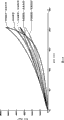
Figure 21 shows is rate of strain frequency that tyre rubber material application frequency-temperature conversion law is calculated and the relation between the energy loss, and this relation is represented with solid line.As shown in the figure, if frequency change, energy loss also takes place significantly to change.But,, can only obtain the energy loss that equates shown in two dash lines even the rate of strain of rubber cast changes according to the method for document (1).Be difficult to obtain to research and develop the useful data of rubber like this.Rate of strain is the product of deformation frequency and strain.
Document is talked about in (2), and rubber cast is set up according to mixing Packed elastomeric material, and has considered strain rate dependency.When calculating the deformation of elastomeric material, the interface of how to handle between filler and the rubber is an important problem.Various results of study show that in the interface, slip between rubber and the filler or friction can cause higher energy loss.Therefore, for elastomeric material is simulated accurately, it is very important respectively filler and rubber being set up model.
Yet, according to the described method of document (2), filler and rubber by whole rather than separate set up model.According to the method, for example interfacial state between rubber and the filler and the information of the stress distribution under the deformation of possible acquisition.
Summary of the invention
Fundamental purpose of the present invention provides a kind of method that can accurately simulate deformed state of elastomeric material etc. by the state that comprises interface between filler and the rubber.
According to the present invention, the method that simulation comprises the deformation of filler part of being made by at least a filler grain and the elastomeric material that centers on this filler rubber part partly comprises following step:
Elastomeric material is separated into the primitive of the formation elastomeric material model of some;
Based on pre-conditioned the elastomeric material model is carried out deformation calculating;
From calculating, deformation obtains the relevant data of physical values distribution with described rubber cast; And show described data; Wherein said separating step comprises the steps:
Filler partly is separated into the primitive of the formation filler model of some; And
The formation that rubber part is separated into some is positioned at the primitive of the rubber cast around the filler model, described rubber pattern
Type has the strain rate dependency that viscoelasticity changes with rate of strain, wherein said rubber cast comprises: contact circumjacent described filler model and have the INTERFACE MODEL and the matrix model that is positioned at described INTERFACE MODEL periphery of the thickness of 1~20nm, the viscoelasticity of described INTERFACE MODEL is softer than described matrix model.
According to analogy method of the present invention, be used for that elastomeric material model that deformation calculates comprises the filler model and around the rubber cast of this filler model.Therefore, might know filler physics value distribution (as stress and energy loss) on every side.Therefore, can carry out more detailed and analysis more specifically.Such physics value data are counted as a distribution table, and this becomes the useful information data that is used to research and develop rubber and/or filler material.
In addition, according to analogy method of the present invention, strain rate dependency is limited in the rubber cast.With a physical property tester rubber is applied periodic strain and tests its viscoelasticity.Yet, current measuring method, the strain frequency is low to moderate 1,000Hz.This is not enough for the cling property of estimating rubber product such as tread-rubber.If strain rate dependency is applied to rubber cast, the viscoelasticity of the high yardstick that can not record by tester can be estimated.
Rubber cast preferably includes INTERFACE MODEL and matrix model.Mix Packed rubber and between filler and rubber, have physical interface.When filler was carbon black, the interface was a physical coupling.When filler was silicon dioxide, the interface was the chemical coupling that relies on coupling agent.Such coupling will be by adjusting INTERFACE MODEL the viscoelasticity of rubber more accurately repeat in non-true mode.Therefore, might fully study and estimate coupling agent.
Description of drawings
Objects and advantages of the present invention can from by with reference to following to current preferred forms description and obtain best understanding in conjunction with wherein accompanying drawing:
Fig. 1 is the stereographic map of an example of the computer equipment that uses of the present invention;
Fig. 2 is the program flow diagram according to best mode for carrying out the invention;
What Fig. 3 showed is the diagram of a preferred forms of elastomeric material model (micromechanism);
That Fig. 4 shows is the shape figure of carbon black;
Fig. 5 is the figure that is used for explaining rubber cast deformation;
Fig. 6 is the enlarged drawing of elastomeric material, comprises a molecular chain structure, the strand of an amplification, and the segment of an amplification;
What Fig. 7 showed is a cancellated example of elastomeric material and the enlarged drawing of its one eight chain elastomeric material model;
Fig. 8 is the figure that is used for explaining the linking point fracture of strand;
Fig. 9 is a parameter lambda
cGraph of a relation with the average chain hop count of individual molecule chain N;
Figure 10 shows is actual stress-strain stress relation as the analog result of matrix model and INTERFACE MODEL;
Figure 11 is the program flow diagram of deformation simulation;
Figure 12 is the graph of a relation that is used for explaining the one-piece construction and the micromechanism of homogenizing method;
Figure 13 shows is true stress-strain stress relation figure as the analog result of elastomeric material model (one-piece construction);
Figure 14 is the true stress-strain stress relation figure that shows the analog result of each model;
Figure 15 is the true stress-strain stress relation figure that shows the analog result of elastomeric material model;
Figure 16 shows the energy loss of elastomeric material model and the graph of a relation between the hardness;
The stress envelope of Figure 17 elastomeric material model;
The energy loss distribution plan of Figure 18 elastomeric material model;
Figure 19 is a stress envelope, and wherein (A) is low speed deformation, (B) is high-velocity deformation;
Figure 20 is the development sequence process flow diagram of tread-rubber; And
The energy loss of the elastomeric material that is to use frequency-temperature conversion law acquisition that Figure 21 shows and the graph of a relation between the rate of strain.
Embodiment
Below in conjunction with accompanying drawing preferred forms of the present invention is described.What Fig. 1 showed is the computer equipment of carrying out analogy method of the present invention.Computer equipment 1 comprises main frame 1a, keyboard 1b and as the mouse 1c of input medium, and as the display 1d of output means.Though show that main frame 1a suitably is equipped with central processing unit (being abbreviated as CPU), read only memory ROM, scratchpad memory, mass storage device such as disk, and drive 1a1 and as the 1a2 of CD-ROM or floppy disk.Its stored of mass storage device is used for the treatment step (that is, program) of manner of execution, and this will be described later.
That Fig. 2 shows is an embodiment of the treatment step of the analogy method according to the present invention.In the present embodiment, at first set up elastomeric material model (step S1).In Fig. 3, can see a example as the elastomeric material model 2 of micromechanism (can be known as " unit ").
In order to form elastomeric material model 2, comprise the filler part made by at least a filler grain and be separated into the little primitive 2a of some, 2b, 2c... around the microcosmos area of the elastomeric material of the rubber part of this filler part with to be analyzed.To each primitive 2a, 2b, 2c... provide and use numerical analysis method to carry out deformation to calculate necessary parameter.Numerical analysis method for example comprises, finite element method, finite volume method, finite difference computing, or boundary element method.
Parameter for example comprises, site coordinate figure, primitive shape, and/or each primitive 2a, 2b, the material property of 2c....In addition, be used for each primitive 2a, 2b, 2c... as the triangle of for example two dimensional surface or quadrilateral primitive with as four sides or six side's primitives of three-dimensional primitive.Therefore, elastomeric material model 2 is the available numeric datas of computer equipment 1.In this embodiment, shown two-dimentional elastomeric material model 2.
The elastomeric material model 2 of present embodiment is with the analysis of accepting to be in during described deformation is simulated hereinafter under the plane deformation state.Therefore, elastomeric material model 2 does not have strain on Z direction (perpendicular to the direction of picture).Vertical and the lateral dimension of the elastomeric material model 2 of present embodiment is set at 300 * 300 nanometers.
In the present embodiment, filler model 3 is based on carbon black and sets up model.It should be noted that filler is not limited to carbon black, and can be silicon dioxide etc. for example.In this example, the physical form of filler model 3 is to determine according to the shape with the carbon black particle in the actual rubber of being filled in of electron microscope imaging.That Fig. 4 shows is the second particle CB of carbon black.More particularly, in the structure of second particle CB, the spherical primary particle 7 irregular three-dimensional bondings that the carbon atom of many about 10 nanometers of each free diameter is formed.Standard in the flat shape of the second particle CB that the filler model 3 of present embodiment is set as at above-mentioned carbon black.
Carbon black has than the hardness of the hard hundred times of base rubber (modulus of longitudinal elasticity).Therefore, filler model 3 is defined as with the elastic body of the modulus of longitudinal elasticity as material character, and stress and strain is directly proportional in deformation is calculated, to such an extent as to not produce power loss in the present embodiment.The number of filler model 3 is done suitable setting based on the filler combined amount of the elastomeric material of analytic target in unit.
In the present invention, define strain rate dependency in rubber cast 4, wherein the stress that produces according to rate of strain changes.Fig. 5 is the concept map that is used for explaining the deformation rule of the rubber cast 4 with strain rate dependency.Each primitive of rubber cast 4 can be with a model representation, the wherein first deformation network A and parallel to each other being connected of the second deformation network B.The stress S that produces in total system is stress that produces in the first deformation network A and the stress sum that produces in the second deformation network B.The coupling because network A and B are connected in parallel to each other, the strain (elongation) that produces in network A and B is identical.
The first deformation network A can be expressed as and be equal to a disc spring.It is a value that is directly proportional with the elongation (strain) of spring that the stress that produces in the first deformation network A is made as.In addition, the elongation of spring only produces owing to bearing a heavy burden.Therefore, do not rely on the stress of rate of strain to result from the first deformation network A.
The second deformation network B can be expressed as a model, and wherein disc spring e and vibroshock p are connected with each other with series system.Vibroshock p is a vibration damping equipment, wherein contains cylinder seal liquid, and a piston that has opening moves in cylinder.This fluid is observed Newton's viscosity law, for example is oil.Produce the resistance that is directly proportional with piston traveling speed among the vibroshock e.The elongation of the whole second deformation network B (strain) equals the elongation sum of spring e and vibroshock p.The stress that produces in the second deformation network B equal to be equivalent to spring e elongation (strain) value.Yet the elongation of spring e is not to determine that according to bearing a heavy burden elongation also is subjected to the influence of the resistance of the vibroshock p relevant with its rate of strain simply.That is to say that the second deformation network B produces the stress that depends on rate of strain.
Below, explain calculation method for stress based on deformation network A and B.
The first deformation network A:
For calculating the stress of the first deformation network A, the eight chain caoutchouc elasticity models that are based on strand network model theory of use.Apply with the stress shown in the following formula (1) with the speed type.
Wherein
C
R=n·k
B·T
N: the strand number of unit volume;
k
B: Boltzmann constant;
T: absolute temperature;
N: the average chain hop count of each strand;
A
Ij: left Cauchy-Green (Cauchy-Green) deformation tensor;
λ
1 2, λ
2 2, λ
3 2Length growth rate on each direction;
L (x): Langevin (Langevin) function;
And
As shown in Figure 6, according to above-mentioned strand network model theory, elastomeric material " a " has the reticulate texture as micromechanism " da ".The reticulate texture of elastomeric material comprises many strand c that are connected in tie point b and arrange unordered.Tie point b comprises intermolecular chemical tie point, for example the chemical crosslinking point.
A strand c comprises a plurality of segment d.Segment d is the minimum constitutional repeating unit in the above-mentioned theory.In addition, a segment d forms by connecting a plurality of primitive f, and carbon atom connects with covalent bond among the primitive f.Each carbon atom rotates freely each other around the key axle between the carbon atom.Therefore, segment d can become different shapes by integrally bending.
In above-mentioned theory, for the cycle of fluctuation of atom, the remaining unchanged for a long period of time of mean place of tie point b.Therefore, can ignore the interference of tie point b.In addition, have two tie point b at two ends, the end-to-end vector of the strand c of b is considered to that non-individual body along with the elastomeric material that strand is embedded into " a " together is out of shape.
As shown in Figure 7, this theory thinks that also the macrostructure of elastomeric material comprises a cube reticulate texture body h, and assembling therein has microcosmic eight chain caoutchouc elasticity model g.In one eight chain caoutchouc elasticity model g, strand c extends to eight tie point b2 that are positioned on each drift angle of cube from a tie point b1 who is positioned at cube center, shown in the enlarged drawing on the right among Fig. 7.By using this model to calculate the stress that produces in the elastomeric material " a ".
For carrying out very accurate simulation, in the first deformation network " A ", the common eight chain caoutchouc elasticity models that propose in the document (1) have been done to improve and use by the following method.
By stretching, elastomeric material can be allowed the tremendous strains that reaches percent good hundreds of.Supposition such as inventor, the tremendous strains of elastomeric material be when as produce during the partial relaxations such as tie point b of the strand c that twines mutually in a jumble.That is to say, as shown in Figure 8, when the drawing stress shown in the arrow Y is added to the strand c1 that links to each other with same tie point b, c2, when c3 and c4 went up, each strand c1 to c4 extended, and tie point b is subjected to huge strain and trend towards breaking (disappearance).Shown in Fig. 8 the right, two strand c1 and c2 form a long strand c5.Strand c3 and c4 move in the same way.In the method for present embodiment, for obtaining an accurate result, also to consider the minimizing of the tie point b of this strand c in the formula (1), as mentioned below.
Here, in reticulate texture body h as shown in Figure 7, k eight chain caoutchouc elasticity models are connected along the direction of axle, height and the degree of depth separately.It should be noted that k is an abundant big number.The sum of the tie point b that comprises in relevant reticulate texture h is called " in conjunction with number ".Suppose in conjunction with number to be " m ", the number of strand c among the reticulate texture h (being the strand number of unit volume matrix model 3) is " n ", and m and n use following formula (2) and formula (3) expression respectively.
m=(k+1)
3+k
3 ...(2)
n=8k
3 ...(3)
Because " k " is enough big number, after several beyond the cube of slightly removing k, above-mentioned equation can be represented with following formula (4) and (5) respectively:
m=2k
3 ...(4)
n=4m ...(5)
In addition, even, be included in the total N of the segment of the strand in the rubber cast 4 because deformation takes place rubber cast 4
AConstant, so formula (6), set up (7) and (8).
N
A=n·N ...(6)
N=N
A/n ...(7)
N=N
A/4m ...(8)
By formula (8) as seen, when the reducing because of load deformation in conjunction with number m of the strand of rubber, the average chain hop count N of individual molecule chain must increase.In other words, by using average chain hop count N as the variable element that has different value according to deformation, the minimizing in conjunction with number m of the strand that causes because of elongation can embody in simulation.This can simulate the deformation mechanism of rubber more accurately, and helps to improve the calculating accuracy.Here, load deformation is the deformation that the deformation of rubber cast 4 increased in writing time.
Average chain hop count N can determine with various distinct methods.For example, average chain hop count N can increase based on the parameter with strain-dependent in load deformation.Parameter with strain-dependent is not particularly limited, and can be for example strain, rate of strain, or a constant I of strain
1In the present embodiment, average chain hop count N is defined by following formula (9).This formula shows that average chain hop count N is a constant I of the strain in relevant rubber cast 4 each primitive
1Function (more particularly, its parameter lambda
cSquare root).
N(λ
c)=A+B·λ
c+C·λ
c 2+D·λ
c 3+E·λ
c 4 ...(9)
Formula (9) is an example of setting up by various experiments, and constant A can be provided with based on the result of the uniaxial tension test of for example elastomeric material easily to E.For example, at first obtain the stress-strain curve of elastomeric material or analytic target.Curve when subsequently, setup parameter n and N make it along unloading.Thereby can determine the segment sum N of strand
A(=nN).Here, because total chain hop count N of strand c
ADuring load deformation and unloading deformation is same value, therefore derives the average chain hop count N in each strain, to meet this curve during unloading.Determine in the formula (9) parameter A to E to meet determined average chain hop count N when the load.In the present embodiment, N=16, as for N in the value of unloading during the deformation, employing be the value of load when finishing.Above-mentioned constant is provided with as follows:
A=+2.9493
B=-5.8029
C=+5.5220
D=-1.3582
E=+0.1325.
Load deformation period average chain hop count N and parameter lambda in Fig. 9, have been shown at each primitive of rubber cast 4
cBetween relation.Correlation parameter λ when strain
cDuring increase, average chain hop count N also increases gradually.In this example, parameter lambda
cOn be limited to 2.5.In the deformation simulation of the elastomeric material model 2 that is described below, during load deformation, the parameter lambda of each primitive of rubber cast 4
cOn constant basis, calculate.The λ that calculates
cIn the substitution formula (9), and the average chain hop count N of calculating during the relevant strain regime of relevant primitive.Here, the numerical value of average chain hop count N remains unchanged during the unloading deformation of rubber cast 4, loads on therebetween to continue in 1 minute to reduce.
The second deformation network B:
Eight chain caoutchouc elasticity models based on strand network model theory also are applied among the spring e of the second deformation network B.Therefore, the stress that produces in the second deformation network B also uses following formula (1) to calculate.Yet, in the second deformation network B, having produced resistance according to rate of strain, this is to ratio of elongation λ
cExert an influence.
Ratio of elongation λ
cBe to calculate from the principal elongation of strand on each direction under the condition of formula (1) description.In the second deformation network B, each principal elongation λ
i (Be)Calculate according to the following steps.Here, subscript " i " represent each direction (i=1,2 ...), if the two dimension, subscript i represents x and y.Upper right mark " Be " is to be used for the symbol distinguished with the principal elongation of the first deformation network A.
At first, according to the relevant shear stress τ in formula (10) the calculating second deformation network B
(B)In formula (10), σ
(B)Be the corresponding stress of the second deformation network B that formerly calculates in the step.In addition, the rate of strain of vibroshock p is by using relevant shear stress τ
(B)With
Value calculate according to formula (11).In the formula (11)
It is the ratio of elongation of vibroshock p.This value is the method that limits according to formula (1), by last calculated value
(being calculated by formula (14) hereinafter described) calculates.
Wherein, parameter c 1 and c2 are respectively the constants of determining according to elastomeric material.
The rate of strain D of vibroshock p
(Bp)Calculate by following formula (12) by rate of strain.The elongation of vibroshock p is by rate of strain D
(Bp)Calculate by following formula (13) and (14).Here, the calculating of subscript t express time step, Δ t represents its increment.
Each elongation of the spring e of the second deformation network B
Calculate according to following formula (15).In formula (15), λ
iThe ratio of elongation of representing the whole second deformation network B.
The stress of the second deformation network B passes through will
Substitution formula (1) is calculated.With the stress of the first deformation network A and the stress addition of the second deformation network B, calculate the integrated stress of rubber cast 4.This stress depends on rate of strain.This correlativity adjusts based on each material constant c1 and the c2 in the formula (11).
Strain rate dependency preferably by in INTERFACE MODEL 5 and the matrix model 6 at least one, best two determine simultaneously.In the present embodiment, both determine strain rate dependency by INTERFACE MODEL 5 and matrix model 6.
In this preferred implementation, should be noted that INTERFACE MODEL 5 has the viscoelasticity that is different from matrix model 6.Here, viscoelasticity comprises the feature of representing with the stress-strain curve under the arbitrary shape variability, as shown in figure 10.For example, the INTERFACE MODEL 5 of present embodiment has the viscoelasticity softer than matrix model 6, like this for little with respect to the slope ratio matrix model 6 of transverse axis of the stress-strain curve of INTERFACE MODEL 5, as shown in figure 10.The hysteresis loop zone of each stress-strain curve still is variable.Under the identical situation of stress, in the present embodiment, viscoelasticity characteristic is set to stress ratio matrix model 6 big of INTERFACE MODEL 5.Yet, be not limited to such embodiment.
Secondly, use set elastomeric material model 2 to carry out deformation and calculate (simulation) (step S3).In Figure 11, shown an example of the specific procedure that deformation is calculated.In simulation, the prime minister imports (step S31) in the computer equipment 1 with data necessary.Import data and comprise, for example, in order to the numeric data of formation elastomeric material model 2, and the various boundary condition that presets.
In computer equipment 1, formed the hard matrix (step S32) of each primitive then, thereafter with integrally-built hard matrix assembling (step S33).Integrally-built hard matrix adopts known nodal displacement and nodal force (step S34), and carries out the analysis of rigidity formula.Determine unknown nodal displacement (step S35), calculate and export physical quantity such as strain, stress, and the principle stress of each primitive (step S36 and S37).In step S38, whether decision finishes to calculate, and does not finish the step that repeating step S32 is later if calculate.
Deformation calculate can use engineering system analytical applications software (as, LS-DYNA etc., Livermore software engineering company (US) exploitation) and improve the employing finite element method and carry out.
In the present embodiment, in order to simulate the deformation of elastomeric material, rubber block mold M is set to as shown in figure 12 to be used for the homogenizing method.Block mold M comprises a large amount of micromechanism unit U that are provided with periodically, and its size is suitable for computer simulation.When the zone in order to simulation is made of the repetition of micromechanism, be difficult to only directly separate with finite element method.Therefore, homogenization process is used.This method comprises the phase one of using the block mold M be equivalent to analyzed area that integral body is simulated, and the result is transformed into the subordinate phase on the micromechanism (unit) of arbitrfary point on the analyzed area.
In addition, in homogenizing method, adopted two groups of independent variables, the x1 and the x2 of the macro-scale of expression block mold M, and the y1 and the y2 of the micro-scale of the unit U of expression elastomeric material model 2, as shown in figure 12.In homogenizing method, each independent quantities of different scale---micro-scale y1, y2 and macro-scale x1, x2 is by asymptotic expansion.Therefore, can obtain to comprise periodically the average dynamic response of the certain size block mold M of unit U.Asymptotic expansion homogenize method is the method for having set up in numerical computation method.This method is for example having a detailed description in the following document.
Higa, Y. and Tomita, Y. work, mechanical property with the sedimentary nickel base superalloy of γ principal phase is calculated prediction, ICM8 journal (Victoria, B.C., Canada), advanced material and mechanical features model, (Ellyin, F., and Prove, J.W. writes), III (1999), 1061-1066, Fleming publishes company limited.
In the present embodiment, constant of formula (1) and (10) etc. is provided with as follows:
C
R=0.268
N=6.6
T=296
k
B=1.38066×10
-29
N
A=4.328×10
26
Filler model volume content: 30%
The longitudinal modulus of elasticity E:100MPa of filler model
The Poisson ratio v of filler model: 0.3.
In the deformation simulation, in the analyzed area of block mold M, produce the uniaxial tensile deformation that equates.Use two tension force conditions, that is, the high-velocity deformation condition, wherein rate of strain on x2 direction as shown in figure 12, equal 1 (/s), and low speed deformation condition, wherein rate of strain equal 0.01 (/s).Under any circumstance, strain is made as 0.15, then, eliminates load, and material is out of shape under each speed.
In deformation is calculated, as mentioned above, calculate the average chain hop count N under each strain regime, again order in these value substitution formulas (1) is calculated.Elastomeric material model 2 (block mold M) adopts is the three-dimensional eight chain caoutchouc elasticity models of Aruuda etc., and does not change the direction (Z-direction among Fig. 3) of thickness.In addition, the average chain hop count N of matrix model 3 and INTERFACE MODEL 5 be provided with as below:
INTERFACE MODEL:
Average chain hop count N during the load deformation
N=-5.9286+20.6175 λ
c-21.8168 λ
c 2+ 10.8227 λ
c 3-1.9003 λ
c 4The segment sum N of strand
A(constant)
N
A=3.203×10
25
The matrix model:
Average chain hop count N during the load deformation
N=-3.2368+20.6175 λ
c-21.8168 λ
c 2+ 10.8227 λ
c 3-1.9003 λ
c 4The segment sum N of strand
A(constant)
N
A=4.3281×10
26
Calculate if carry out deformation, might get data necessary (step S4), for example physical quantity of each timing of each calculation procedure from deformation result of calculation.Figure 13 is to use the true stress-strain stress relation figure of the elastomeric material model of result of calculation formation; As seen from the figure, elastomeric material model 2 demonstrates different viscoelasticity characteristics according to rate of strain.As this Simulation result, to follow with the low speed deformation (dotted line) under actual elastomeric material situation and compare, material hardening phenomenon occurred under high-velocity deformation.With regard to high-velocity deformation, be greater when having proved energy loss than low speed deformation.
Figure 14 is another result of present embodiment.In the present embodiment, only in INTERFACE MODEL, defined strain rate dependency, and in the matrix model, do not defined.The exemplary of filler is carbon black and silicon dioxide.Maximum difference between them does not lie in filler itself, and is the interface between filling surface and rubber.It is generally acknowledged that the rubber that is positioned near interface is comparatively responsive to the influence of material behavior, and very high with the correlativity of rate of strain.Therefore, by changing the strain rate dependency of INTERFACE MODEL and matrix model, how can effectively to obtain filler and the polymkeric substance significant data of coupling each other.
In each INTERFACE MODEL, defined strain rate dependency as shown in figure 14.In this example, the INTERFACE MODEL 1 that contains carbon black has the large strain rate correlativity, and energy loss also is provided with greatlyyer.The INTERFACE MODEL 2 that contains silicon dioxide has the small strain rate dependence, and energy loss also is provided with lessly.Among the figure, the rate of strain of high-velocity deformation be 1,000 (/s) and the rate of strain of low speed deformation be 0.1 (/s).
Used two kinds of elastomeric material models, i.e. INTERFACE MODEL 1 and 2, and simulation is carried out with high-velocity deformation.What Figure 15 showed is analog result.Ordinate is strain, and horizontal ordinate is a true stress.Found that thus though be that variation has taken place for the strain rate dependency of little thickness INTERFACE MODEL, the viscoelasticity characteristic of elastomeric material has produced big difference.
Among Figure 16, horizontal ordinate is represented elastic modulus (with respect to the slope of the horizontal ordinate of Figure 15), and ordinate is represented energy loss (hysteresis loop).As for the cling property of above-mentioned tire, more desirable to the viscoelasticity characteristic that extends along upper left side among the figure.
The simulation of present embodiment comprises and forms and show step (step S5) from the distribution plan of the data that obtain.What Figure 17 showed is when high-velocity deformation, under the maximum strain state, and an example of the stress envelope that produces in each primitive of unit U (being the unit U shown in Figure 12 rather than Fig. 3).In addition, also shown the variation of the appearance profile of unit U.But the step that forms distribution plan is to be undertaken by the stress value that information such as chromatic information (color saturation, tone, brightness etc.) with visual identity substitute each primitive that obtains.In Figure 17, the local strain that color saturation is big more is big more.Found that thus the spacing between the concentrated more local filler model 3 and 3 of stress is little.Find also that simultaneously the higher place of stress is to become linear linking to each other along draw direction in filler model 3.
Figure 18 is the energy loss distribution plan that produces in each primitive of high-velocity deformation lower unit U.For obtaining energy loss, unload load with the speed identical, thereby obtained a round-robin stress-strain curve with each rate of strain.Use the appearance profile of unit U as shown in figure 17.Still in this distribution plan, substitute the energy loss of resulting each primitive with color information (color saturation, tone, brightness etc.).Strain is big more, and color saturation is big more.The result finds equally thus, and the spacing that produces between the big more local filler model 3 and 3 of stress is more little.Filler model 3 is colored, but does not have the produce power loss.In addition, data such as the physical values that uses in the distribution plan are not limited to stress value or energy loss, but can adopt different values according to analysis purpose.
Figure 19 (A) and 19 (B) are respectively when high-velocity deformation and low speed deformation, and at the stress distribution partial enlarged view of maximum strain state lower unit U, it has shown stress distribution conformal frequency conversion rate difference under strain the same terms and the state that changes.That is to say, when high-velocity deformation, heavily stressed being created in the relative broad range, and this phenomenon is particularly evident between filler model 3 and 3.
When filler and rubber when being modeled together shown in the document (2), the stress distribution of unit is uniformly, and model only is deformed into rectangle physically.Therefore, this distribution plan only could obtain at rubber with after being used to be received in the separated and modeling of the filler of rubber.
This distribution plan provides extremely useful information to developing actual elastomeric material.For example, at the filler that is used for being received in rubber, preferably those have the filler that the homogeneous state of stress distributes when deformation.In order to develop this filler that is used to insert elastomeric material, importantly at first know current stress distribution.By its result, might improve the distribution property and the physical aspect of filler, to reduce the variation of spacing between the filler as far as possible.Use this improved filler model, formed the unit once more, the deformation simulation of carrying out repeatedly on computers distributes up to obtaining more excellent uniform stress.
When obtaining more uniform stress distribution by calculating, the physical arrangement of unit, promptly the particle shape of filler, distributed degrees etc. preferably can be reacted actual manufacturing.The distribution of filler especially can enough three parameters control, i.e. the filler combined amount in rubber, incorporation time and mixing temperature.Therefore, if can obtain the distribution property of ideal filler model 3, then might develop a kind of the have rubber composition for tire of outstanding antiskid or the elastomeric material that has outstanding fuel efficiency within a short period of time.
Analogy method of the present invention can be used to for example airtyred tread-rubber of exploitation effectively.As mentioned above, preferably, if complex elastic modulus is bigger and energy loss is littler when the deformation of rubber low speed, the fuel efficiency of tread-rubber is just more outstanding.Here, the fuel efficiency index X1 of tread-rubber can use following formula (16) expression, and the rubber that index X1 is big more is more desirable:
X1=K1·tanδ
L+K2·E
L*
-1 ...(16),
Wherein, K1 and K2 are constant, tan δ
LExpression is used to insert the loss tangent of filler under the characteristic frequency of 10 to 100Hz scopes of rubber, E
L* expression is used to insert the complex elastic modulus of filler under 10 to 100Hz specific deformation frequency scope of rubber.
On the other hand, the energy loss of rubber when high-velocity deformation is big more, and the cling property of tread-rubber is outstanding more.Here, the cling property index X2 of tread-rubber can use following formula (17) expression, and the rubber that index X2 is big more is more desirable:
X2=K3·tan?δ
H ...(17),
Wherein, K3 is a constant, tan δ
HExpression is used to insert the filler of rubber 10
4To 10
6Loss tangent in the specific deformation frequency scope of Hz.
Figure 20 is to use the process flow diagram of an example of the method for analogy method of the present invention exploitation tread-rubber.In the present embodiment, at first set up elastomeric material model 2 (step Sal), and under low speed deformation, carry out the deformation simulation based on this.Then, calculate the index X1 (step Sa2) relevant with fuel efficiency.Based on same elastomeric material model 2, carrying out the deformation simulation under the distortion at a high speed.Then, calculate the index X2 (step Sa3) relevant with cling property.Step Sa2 and Sa3 can parallel connection carry out or inverted order is carried out.
In order to satisfy fuel efficiency and cling property simultaneously, preferred index X1 and X2 sum are the bigger the better.Therefore, in the present embodiment, determine whether index X1 and X2 sum reach maximal value (step Sa4).If be judged as among the step Sa4 very, then according to the elastomeric material model of being set up 2 (unit U) prototype and design practical filling material and rubber composition.If be judged as vacation among the step Sa4, change the parameter of unit U, set up elastomeric material model 2 (step Sa1) once more.Then, repeat the deformation simulation with the same manner, (X1+X2) obtains maximal value up to exponential sum.
The example of the parameter that need change has slope (the parameter such as the C in the formula (1) of stress-strain diagram
RAnd N), the amplitude of hysteresis loop (λ among Fig. 9
cAnd strain rate dependency (material constant of formula (11)) slope with N).As mentioned above, analogy method of the present invention is very useful to developing concrete various rubber product.
Claims (7)
1. method of simulating deformation of rubber material, it is characterized in that, described elastomeric material comprises filler part of being made by at least a filler grain and the rubber part that centers on this filler part, and rubber cast is included in the elastomeric material model, and described method comprises following step:
Described elastomeric material is separated into the primitive of the formation elastomeric material model of some;
Based on pre-conditioned described elastomeric material model is carried out deformation calculating;
From calculating, described deformation obtains the relevant data of physical values distribution with rubber cast; And
Show described data; Wherein
Described separating step comprises the steps:
Described filler partly is separated into the primitive of the formation filler model of some; And
Described rubber part is separated into the primitive of the rubber cast around the described filler model of being positioned at of some, and described rubber cast has the strain rate dependency that viscoelasticity changes with rate of strain, and wherein said rubber cast comprises:
Contact circumjacent described filler model and have 1~20nm thickness INTERFACE MODEL and
Be positioned at the matrix model of described INTERFACE MODEL periphery, the viscoelasticity of described INTERFACE MODEL is softer than described matrix model.
2. the method for simulation deformation of rubber material as claimed in claim 1 is characterized in that,
Described method comprises that further the mode with figure shows the step of described at least a data.
3. the method for simulation deformation of rubber material as claimed in claim 1 is characterized in that,
Described data comprise the stress and/or the energy loss of each primitive of rubber cast.
4. the method for simulation deformation of rubber material as claimed in claim 1 is characterized in that,
Described strain rate dependency only is limited in the described INTERFACE MODEL.
5. the method for simulation deformation of rubber material as claimed in claim 1 is characterized in that,
The thickness of described INTERFACE MODEL is arranged in the scope of 5~10nm.
6. the method for simulation deformation of rubber material as claimed in claim 1 is characterized in that,
Described step of carrying out deformation calculating comprises the steps:
Under the low deformation frequency of 10~100Hz, carry out the deformation simulation first time of described elastomeric material model;
By using the Simulation result of deformation for the first time, calculate the index X1 of the low speed deformation of the described elastomeric material model of expression;
10
4~10
6Under the high deformation frequency of Hz, carry out the deformation simulation second time of described elastomeric material model;
By using the Simulation result of deformation for the second time, calculate the index X2 of the high-velocity deformation of the described elastomeric material model of expression;
Gauge index X1 and X2 and; And
Repeat at least one parameter that described first time of deformation simulation and the simulation of deformation for the second time change described elastomeric material model simultaneously, until index X1 and X2's and be maximal value.
7. the method for simulation deformation of rubber material as claimed in claim 6 is characterized in that,
Described index X1 and X2 calculate according to following formula:
X1=K1tan δ
L+ K2E
L*
-1With
X2=K3tan δ
H, wherein
" K1 ", " K2 " and " K3 " are constant, " tan δ
L" loss tangent of the described filler part of expression under the frequency of 10 to 100Hz scopes, " E
L* " complex elastic modulus and " the tan δ of the described filler part of expression under 10 to 100Hz deformation frequency
H" represent that described filler part is 10
4To 10
6Loss tangent under the deformation frequency of Hz.
Applications Claiming Priority (3)
| Application Number | Priority Date | Filing Date | Title |
|---|---|---|---|
| JP2004-330846 | 2004-11-15 | ||
| JP2004330846A JP4594043B2 (en) | 2004-11-15 | 2004-11-15 | Rubber material simulation method |
| JP2004330846 | 2004-11-15 |
Publications (2)
| Publication Number | Publication Date |
|---|---|
| CN1776696A CN1776696A (en) | 2006-05-24 |
| CN1776696B true CN1776696B (en) | 2010-09-22 |
Family
ID=35811561
Family Applications (1)
| Application Number | Title | Priority Date | Filing Date |
|---|---|---|---|
| CN2005101246902A Expired - Fee Related CN1776696B (en) | 2004-11-15 | 2005-11-07 | Method of simulating deformation of rubber material |
Country Status (6)
| Country | Link |
|---|---|
| US (1) | US7292966B2 (en) |
| EP (1) | EP1657657B1 (en) |
| JP (1) | JP4594043B2 (en) |
| KR (1) | KR101085174B1 (en) |
| CN (1) | CN1776696B (en) |
| TW (1) | TWI344611B (en) |
Families Citing this family (35)
| Publication number | Priority date | Publication date | Assignee | Title |
|---|---|---|---|---|
| DE602004023360D1 (en) * | 2003-10-17 | 2009-11-12 | Sumitomo Rubber Ind | Method for simulating viscoelastic material |
| JP4697870B2 (en) * | 2005-10-07 | 2011-06-08 | 住友ゴム工業株式会社 | Simulation method for viscoelastic materials |
| JP4685747B2 (en) * | 2006-11-09 | 2011-05-18 | 住友ゴム工業株式会社 | How to create a rubber material analysis model |
| JP4833870B2 (en) | 2007-01-16 | 2011-12-07 | 富士通株式会社 | Analytical model creation device, analytical model creation program, analytical model creation method, and electronic device design method for elastic material member with strong nonlinearity |
| JP5012094B2 (en) * | 2007-03-06 | 2012-08-29 | 横浜ゴム株式会社 | Viscoelastic property determination method, simulation program and simulation apparatus, and simulation method using simulation model with viscoelastic property |
| JP5001883B2 (en) * | 2008-03-12 | 2012-08-15 | 住友ゴム工業株式会社 | Rubber material simulation method |
| JP5215053B2 (en) * | 2008-06-16 | 2013-06-19 | 株式会社ブリヂストン | Crosslinking rubber simulation method |
| JP4603082B2 (en) * | 2009-02-03 | 2010-12-22 | 株式会社ブリヂストン | Rubber material deformation behavior prediction apparatus and rubber material deformation behavior prediction method |
| JP4852626B2 (en) * | 2009-04-28 | 2012-01-11 | 日東電工株式会社 | Program and apparatus for outputting stress-strain curve formula and method for evaluating physical properties of elastic material |
| JP5559594B2 (en) * | 2010-05-20 | 2014-07-23 | 住友ゴム工業株式会社 | Rubber material simulation method |
| JP5039178B2 (en) * | 2010-06-21 | 2012-10-03 | 住友ゴム工業株式会社 | Method for simulating products made of viscoelastic materials |
| JP5623859B2 (en) * | 2010-10-05 | 2014-11-12 | 株式会社ブリヂストン | Elastic response performance prediction method, design method, and elastic response performance prediction apparatus for rubber products |
| JP5227436B2 (en) | 2011-03-18 | 2013-07-03 | 住友ゴム工業株式会社 | How to create a finite element model of filler compounded rubber |
| US10292775B2 (en) | 2011-08-26 | 2019-05-21 | Brainlab Ag | Systems and method for determining the shape of a surgical instrument and surgical instruments having a deformable body |
| JP2013057638A (en) * | 2011-09-09 | 2013-03-28 | Sumitomo Rubber Ind Ltd | Simulation method for rubber materials |
| JP5395864B2 (en) * | 2011-09-14 | 2014-01-22 | 住友ゴム工業株式会社 | Rubber material simulation method |
| JP5503618B2 (en) * | 2011-10-03 | 2014-05-28 | 住友ゴム工業株式会社 | Rubber material simulation method |
| JP5555216B2 (en) * | 2011-10-20 | 2014-07-23 | 住友ゴム工業株式会社 | Simulation model generation method for filler compounding materials. |
| JP2013108800A (en) * | 2011-11-18 | 2013-06-06 | Sumitomo Rubber Ind Ltd | Method for simulating rubber material |
| KR101293982B1 (en) * | 2011-12-08 | 2013-08-07 | 현대자동차주식회사 | Method for simulating elastomer |
| JP5466727B2 (en) * | 2012-05-16 | 2014-04-09 | 住友ゴム工業株式会社 | Method for simulating polymer materials |
| JP2014010047A (en) * | 2012-06-29 | 2014-01-20 | Nitto Denko Corp | Program for outputting stress/strain curve equation and its device and method for evaluating physical property of elastic material |
| EP3051444A4 (en) * | 2013-10-07 | 2017-06-21 | Sumitomo Rubber Industries, Ltd. | Method for creating finite element model for filler-containing rubber |
| JP6048358B2 (en) * | 2013-10-08 | 2016-12-21 | トヨタ自動車株式会社 | Analysis device |
| JP5913260B2 (en) * | 2013-11-14 | 2016-04-27 | 住友ゴム工業株式会社 | Method for simulating polymer materials |
| KR20160024552A (en) * | 2014-08-26 | 2016-03-07 | 삼성전자주식회사 | Method and apparatus for modeling deformable body comprising particles |
| CN104807432A (en) * | 2015-05-19 | 2015-07-29 | 重庆大学 | Soft measuring method of axial deformation quantity of rectangular rubber sealing ring based on flexible screwing assembly |
| WO2017033414A1 (en) * | 2015-08-24 | 2017-03-02 | 高周波粘弾性株式会社 | Tire and tire characteristic evaluating method |
| JP6552938B2 (en) * | 2015-10-15 | 2019-07-31 | Toyo Tire株式会社 | Method, apparatus and program for calculating hysteresis loss of filler filled rubber |
| CN105806302B (en) * | 2016-03-25 | 2018-03-30 | 首钢总公司 | The experimental method of inside steel billet metal strain in a kind of test operation of rolling |
| KR102013808B1 (en) | 2017-11-22 | 2019-08-23 | 한국과학기술원 | Simulation Method of Deformable Objects using Surface Approximation Function |
| CN109325253B (en) * | 2018-08-01 | 2023-05-26 | 苏州智道势能信息科技有限公司 | Sealing element tightness simulation test method |
| CN109766669B (en) * | 2019-03-06 | 2022-09-27 | 四川大学 | Visual mathematical model method for predicting resistance and response of conductive composite material |
| CN110688794B (en) * | 2019-09-24 | 2023-05-02 | 青岛科技大学 | Inflation-free tire finite element simulation analysis and performance optimization method |
| CN115034052A (en) * | 2022-05-30 | 2022-09-09 | 广东时谛智能科技有限公司 | Sole model elastic display method, device, equipment and storage medium |
Citations (1)
| Publication number | Priority date | Publication date | Assignee | Title |
|---|---|---|---|---|
| CN1532034A (en) * | 2003-03-26 | 2004-09-29 | 超 吴 | Process for producing concrete analogue forming rubber mold |
Family Cites Families (3)
| Publication number | Priority date | Publication date | Assignee | Title |
|---|---|---|---|---|
| JP4103949B2 (en) | 2000-10-16 | 2008-06-18 | 横浜ゴム株式会社 | Rubber composite design method |
| JP3466584B2 (en) | 2001-06-06 | 2003-11-10 | 住友ゴム工業株式会社 | Simulation method for predicting the performance of products made of viscoelastic materials |
| JP3668238B2 (en) * | 2003-10-17 | 2005-07-06 | 住友ゴム工業株式会社 | Rubber material simulation method |
-
2004
- 2004-11-15 JP JP2004330846A patent/JP4594043B2/en not_active Expired - Fee Related
-
2005
- 2005-09-16 US US11/227,518 patent/US7292966B2/en not_active Expired - Fee Related
- 2005-09-21 TW TW094132603A patent/TWI344611B/en not_active IP Right Cessation
- 2005-10-10 EP EP05022052A patent/EP1657657B1/en not_active Expired - Fee Related
- 2005-11-07 CN CN2005101246902A patent/CN1776696B/en not_active Expired - Fee Related
- 2005-11-10 KR KR1020050107546A patent/KR101085174B1/en not_active IP Right Cessation
Patent Citations (1)
| Publication number | Priority date | Publication date | Assignee | Title |
|---|---|---|---|---|
| CN1532034A (en) * | 2003-03-26 | 2004-09-29 | 超 吴 | Process for producing concrete analogue forming rubber mold |
Non-Patent Citations (1)
| Title |
|---|
| JP特开2002-365205A 2002.12.18 |
Also Published As
| Publication number | Publication date |
|---|---|
| EP1657657A3 (en) | 2006-06-07 |
| JP4594043B2 (en) | 2010-12-08 |
| KR20060054142A (en) | 2006-05-22 |
| TW200615820A (en) | 2006-05-16 |
| TWI344611B (en) | 2011-07-01 |
| US7292966B2 (en) | 2007-11-06 |
| JP2006138810A (en) | 2006-06-01 |
| CN1776696A (en) | 2006-05-24 |
| EP1657657A2 (en) | 2006-05-17 |
| KR101085174B1 (en) | 2011-11-18 |
| US20060106586A1 (en) | 2006-05-18 |
| EP1657657B1 (en) | 2011-06-29 |
Similar Documents
| Publication | Publication Date | Title |
|---|---|---|
| CN1776696B (en) | Method of simulating deformation of rubber material | |
| KR101083654B1 (en) | Method of simulating viscoelastic material | |
| Gipser | FTire: a physically based application-oriented tyre model for use with detailed MBS and finite-element suspension models | |
| JP3668238B2 (en) | Rubber material simulation method | |
| Rahman et al. | Stress-strain characteristics of flexible pavement using finite element analysis | |
| CN104182585B (en) | Silicone elastomer body feel is analyzed and the Finite Element Method of fatigue life prediction | |
| Yan | A boundary element modeling of fatigue crack growth in a plane elastic plate | |
| Sladek et al. | Meshless local Petrov-Galerkin method for continuously nonhomogeneous linear viscoelastic solids | |
| WO2013042600A1 (en) | Stress-strain relation simulation method, stress-strain relation simulation system, and stress-strain relation simulation program which use chaboche model | |
| CN109470553B (en) | Method for realizing rapid conversion of material parameters of asphalt mixture by applying Laplace transformation | |
| JP2005186900A (en) | Simulation method for tire | |
| CN107480395A (en) | A kind of construction method and system of vehicle steering knuckle loading spectrum forecast model | |
| JP6613724B2 (en) | Method for creating composite material analysis model, computer program for creating composite material analysis model, composite material simulation method, and composite material simulation computer program | |
| JP5432549B2 (en) | Rubber material simulation method | |
| JP3668239B2 (en) | Simulation method for viscoelastic materials | |
| Tabourot et al. | Compartmentalized model for the mechanical behavior of titanium | |
| CN106407546A (en) | Method for analyzing local deformation of transmission housing by using original point dynamic stiffness characteristic | |
| CN104765928B (en) | A kind of Plastic Forming frictional behavior measuring method | |
| CN115081284A (en) | Key response equivalence-based pavement structure layer equivalent modulus determination method and device and storage medium | |
| CN111400955B (en) | Evaluation method for fatigue cracking damage of asphalt pavement caused by temperature change | |
| CN115270304A (en) | Method for determining fatigue load of chassis part rack | |
| EP4016367A1 (en) | Computationally efficient method for obtaining performing gears | |
| YOSHIDA et al. | Multiscale Simulation Technology and Software for Soft Matter | |
| Wang et al. | Two-step method for bridge modal mass identification using synchronously measured bridge and vehicle dynamic responses | |
| JP2017224202A (en) | Simulation method for polymeric material |
Legal Events
| Date | Code | Title | Description |
|---|---|---|---|
| C06 | Publication | ||
| PB01 | Publication | ||
| C10 | Entry into substantive examination | ||
| SE01 | Entry into force of request for substantive examination | ||
| C14 | Grant of patent or utility model | ||
| GR01 | Patent grant | ||
| CF01 | Termination of patent right due to non-payment of annual fee |
Granted publication date: 20100922 Termination date: 20201107 |
|
| CF01 | Termination of patent right due to non-payment of annual fee |