Positioner, localization method, housing and mobile communication terminal
Technical field
The present invention relates to be applied to the positioner and the localization method of mobile communication terminal and analog, more specifically, relate to housing and the mobile communication terminal of having used above-mentioned positioner.
Background technology
When member is combined in the housing, normally by the housing align member with in conjunction with this member (for example, with reference to Japanese Patent Laid Open Publication No.11-331333 and Japanese Patent Laid Open Publication No.2000-223858).
Yet in Japanese Patent Laid Open Publication No.11-331333 and Japanese Patent Laid Open Publication No.2000-223858, buffer component or filler are inserted between housing and the combined member, and have therefore increased the quantity of parts, produce the possibility that cost increases.
Therefore, the existing technology that proposes relates to by being formed on positioning convex on the shell inner surface and is assembled to and locatees combined member (for example, with reference to the open No.04-344112 of Japan Patent) in the location indentations that is formed in the member for the treatment of combination.If use this positioner, can locate combined member so and do not increase the quantity of parts.
Below, will the traditional positioner that be applied to portable phone (mobile communication terminal) be described with reference to figure 7.
Fig. 7 is the phantom for the portable phone that the positioner in the conventional example is shown, and particularly, is the phantom of the display part in the Collapsible mobile phone.
The outward appearance of the display part of Collapsible mobile phone shown in Figure 7 comprises: form housing 100 closedtop lid 101 and underseal lid 102, be assembled to the transparent panel 103 among the display window 101a of closedtop lid 101 and cover the decoration panel 104 of underseal lid 102.Be combined with the display floater 105 of character display and analog in the inside of housing 100, from the back of the body surface of display floater 105 with the lighting unit 106 of its illumination and the built-in framework 107 of these members of clamping.
Be assembled together with positioning convex 101b on the inner surface that is formed on closedtop lid 101 by the location indentations 107a that will be formed in the built-in framework 107, carry out the location of built-in framework 107.And in the example depicted in fig. 7, by closedtop lid 101 and underseal lid 102 screws that are fixed together 108 are fixed built-in framework 107 in the mode of uniting clamping.
It is subsidiary that what mention is that in Collapsible mobile phone shown in Figure 7, if housing 100 and built-in framework 107 are by being out of shape such as falling the impact that causes, stress concentrates on the positioning convex 101b so.Therefore, concentrate preferably for the sufficiently high intensity of the protruding 101b in location with renitency.
Yet, if increase the size of positioning convex 101b, be the defective appearance that is easy to take place such as shrinkage housing 100 molded so, and therefore be difficult to enough intensity, consequently exist by the possibility that positioning convex 101b is broken such as falling the impact that causes to the protruding 101b in location.
It is subsidiary that what mention is that as shown in Figure 8, also possible is the location of carrying out built-in framework 107 by the periphery of use fixing lug boss 102a.Yet, in this case, need to consider by the expansion of the fastening fixing lug boss 102a that causes of screw 108 with thus to the restriction of setting accuracy.
Summary of the invention
Of the present invention have a purpose that a kind of positioner, localization method, housing and mobile communication terminal are provided, although its by improving positioning convex intensity and also during housing is molded, on shell inner surface, form the open defect that positioning convex does not still cause simultaneously, can solve the positioning convex that is formed on the shell inner surface owing to such as falling the problem that the impact that causes is broken.
For achieving the above object, the invention provides and a kind ofly can will be combined in combined member positioning means for positioning in the described housing with respect to housing.This positioner is formed by being formed on the location indentations in the combined member and being formed on the inner surface of housing and by the positioning convex that is assembled to the described combined member in location in the described location indentations, and described positioning convex is formed by rib.
Because this structure,, still can improve the intensity of positioning convex and do not cause open defect in the housing even positioning convex is formed on the inner surface of housing.As this result, concentrate with opposing stress by giving the protruding sufficiently high intensity in location, can prevent positioning convex owing to fall and the breaking of analogue.
Positioner of the present invention is constructed by this way, and promptly described positioning convex is formed by the rib that continues on both direction at least.
Because this structure, positioning convex form for example rib of quadrilateral shape, three-pointed hollow star, hollow circular, cross, X-shaped structure, ∏ shape structure and C shape structure, thereby can improve the intensity of positioning convex.
Positioner of the present invention is constructed by this way, and promptly described positioning convex is formed by the rib that the mode with ring-type continues.
Because this structure, positioning convex can form for example rib of quadrilateral shape, three-pointed hollow star and hollow circular, thereby can further improve the intensity of positioning convex.
Positioner of the present invention is constructed by this way, promptly described positioning convex be arranged in to the described combined member of major general be fixed to described housing screw part near.
Because this structure can be subjected to being concentrated by the stress that reduces positioning convex when falling the impact that causes at positioning convex.And, because can be, also can solve the fastening force that during fastening screw becomes inclination and screw and act on the positioning convex, as a result the positioning convex problem of breaking with the screw localization part of the screw of hi-Fix housing part and combined member.
Positioner of the present invention is constructed by this way, promptly forms in the head portion of described rib and guides curved surface or the inclined surface that is assembled in the described location indentations.
Because this structure, location indentations and positioning convex be assembled together to become easily, and therefore can improve the assembling performance.
The invention provides a kind of method that is used for to be combined in the combined member location of described housing with respect to housing.This localization method relates to following steps: will be formed on by the positioning convex that rib forms on the inner surface of described housing; With described positioning convex is assembled in the location indentations that is formed in the described combined member, thereby locate described combined member.
Because the method,, still can improve the intensity of positioning convex and do not cause open defect in the housing even positioning convex is formed on the inner surface of housing.As this result, concentrate with opposing stress by giving the protruding sufficiently high intensity in location, can prevent positioning convex owing to fall and the breaking of analogue.
In localization method of the present invention, described positioning convex is formed by the rib that continues on both direction at least.
Because the method, positioning convex form for example rib of quadrilateral shape, three-pointed hollow star, hollow circular, cross, X-shaped structure, ∏ shape structure and C shape structure, thereby can improve the intensity of positioning convex.
In localization method of the present invention, described positioning convex is formed by the rib that the mode with ring-type continues.
Because the method, positioning convex can form for example rib of quadrilateral shape, three-pointed hollow star and hollow circular, thereby can further improve the intensity of positioning convex.
In localization method of the present invention, described positioning convex be arranged in to the described combined member of major general be fixed to described housing screw part near.
Because the method, can be subjected to concentrating at positioning convex by the stress that reduces positioning convex when falling the impact that causes.And, because can be, also can solve the fastening force that during fastening screw becomes inclination and screw and act on the positioning convex, as a result the positioning convex problem of breaking with the screw localization part of the screw of hi-Fix housing part and combined member.
In localization method of the present invention, in the head portion of described rib, form and guide curved surface or the inclined surface that is assembled in the described location indentations.
Because the method, location indentations and positioning convex be assembled together to become easily, and therefore can improve the assembling performance.
The invention provides a kind of housing that wherein is combined with combined member, and this housing comprises positioning convex integratedly, described positioning convex is located described combined member by being assembled to the location indentations that is formed in the described combined member, and described positioning convex is formed by rib.
Because this structure forms on the surface in the housing of positioning convex within it, can improve the intensity of positioning convex and do not cause open defect in the housing.As this result, concentrate with opposing stress by giving the protruding sufficiently high intensity in location, can prevent positioning convex owing to fall and the breaking of analogue.
Housing of the present invention is constructed by this way, and promptly described positioning convex is formed by the rib that continues on both direction at least.
Because this structure, positioning convex form for example rib of quadrilateral shape, three-pointed hollow star, hollow circular, cross, X-shaped structure, ∏ shape structure and C shape structure, thereby can improve the intensity of positioning convex.
Housing of the present invention is constructed by this way, and promptly described positioning convex is formed by the rib that the mode with ring-type continues.
Because this structure, positioning convex can form for example rib of quadrilateral shape, three-pointed hollow star and hollow circular, thereby can further improve the intensity of positioning convex.
Housing of the present invention is constructed by this way, promptly described positioning convex be arranged in to the described combined member of major general be fixed to described housing screw part near.
Because this structure can be subjected to being concentrated by the stress that reduces positioning convex when falling the impact that causes at positioning convex.And, because can be, also can solve the fastening force that during fastening screw becomes inclination and screw and act on the positioning convex, as a result the positioning convex problem of breaking with the screw localization part of the screw of hi-Fix housing part and combined member.
Housing of the present invention is constructed by this way, promptly forms in the head portion of described rib and guides curved surface or the inclined surface that is assembled in the described location indentations.
Because this structure, location indentations and positioning convex be assembled together to become easily, and therefore can improve the assembling performance.
The invention provides a kind of mobile communication terminal with the housing that wherein is combined with built-in framework, this mobile communication terminal comprises on location indentations that is formed in the described built-in framework and the inner surface that is formed on described housing and by being assembled to the positioning convex of the described built-in framework in location in the described location indentations, positioning convex is formed by rib.
Because this structure,, still can improve the intensity of positioning convex and do not cause open defect in the housing even positioning convex is formed on the inner surface of housing.As this result, concentrate with opposing stress by giving the protruding sufficiently high intensity in location, can prevent positioning convex owing to fall and the breaking of analogue.
Mobile communication terminal of the present invention is constructed by this way, and promptly described positioning convex is formed by the rib that continues on both direction at least.
Because this structure, positioning convex form for example rib of quadrilateral shape, three-pointed hollow star, hollow circular, cross, X-shaped structure, ∏ shape structure and C shape structure, thereby can improve the intensity of positioning convex.
Mobile communication terminal of the present invention is constructed by this way, and promptly described positioning convex is formed by the rib that the mode with ring-type continues.
Because this structure, positioning convex can form for example rib of quadrilateral shape, three-pointed hollow star and hollow circular, thereby can further improve the intensity of positioning convex.
Mobile communication terminal of the present invention is constructed by this way, promptly described positioning convex be arranged in to the described built-in frame fixation of major general to the screw of described housing part near.
Because this structure can be subjected to being concentrated by the stress that reduces positioning convex when falling the impact that causes at positioning convex.And, because can be, also can solve the fastening force that during fastening screw becomes inclination and screw and act on the positioning convex, as a result the positioning convex problem of breaking with the screw localization part of the screw of hi-Fix housing part and combined member.
Mobile communication terminal of the present invention is constructed by this way, promptly forms in the head portion of described rib and guides curved surface or the inclined surface that is assembled in the described location indentations.
Because this structure, location indentations and positioning convex be assembled together to become easily, and therefore can improve the assembling performance.
As mentioned above, according to the present invention,, still can improve the intensity that is formed on the positioning convex on the shell inner surface and do not cause open defect although positioning convex is formed on the inner surface of housing.As a result, concentrate with opposing stress, can prevent that positioning convex is owing to breaking such as falling the impact that causes by giving the protruding sufficiently high intensity in location.
Description of drawings
Fig. 1 is the stereogram of portable phone;
Fig. 2 is the exploded perspective view of display part;
Fig. 3 is the part exploded perspective view of closedtop lid and built-in framework;
Fig. 4 is the part exploded perspective view of display part;
Fig. 5 is the cutaway view of the display part of being got of the line A-A along Fig. 1;
Fig. 6 A to Fig. 6 H is each key diagram that shows the embodiment of various positioning convex;
Fig. 7 is for being illustrated in the phantom of the portable phone of positioner in the conventional example; And
Fig. 8 is for being illustrated in the phantom of the portable phone of positioner in another conventional example.
Embodiment
Below, will provide and will be applied to the description of the portable phone on it according to the positioner (localization method) of the embodiment of the invention referring to figs. 1 to Fig. 6 A to Fig. 6 H.
Fig. 1 is the stereogram of portable phone, Fig. 2 is the exploded perspective view of display part, Fig. 3 is the part exploded perspective view of closedtop lid and built-in framework, Fig. 4 is the part exploded perspective view of display part, Fig. 5 is the cutaway view of the display part of being got of the line A-A along Fig. 1, and Fig. 6 A to Fig. 6 H each show the key diagram of the embodiment of various positioning convex.
As shown in Figure 1, by operation part (main body) 20 and display part 30 are linked together collapsibly via hinge part 10, structure is according to the portable phone of this embodiment.
As shown in Figure 2, the outward appearance of display part 30 is made of the closedtop lid 32 of forming housing 31 and underseal lid 33, the decoration panel 35 that is assemblied in the transparent panel 34 among the display window 32a and covers underseal lid 33.Be combined with the display floater 36 of character display and analog in the inside of housing 31, from the back of the body surface of display floater 36 with the lighting unit 37 of its illumination and the built-in framework 38 of these members of clamping.
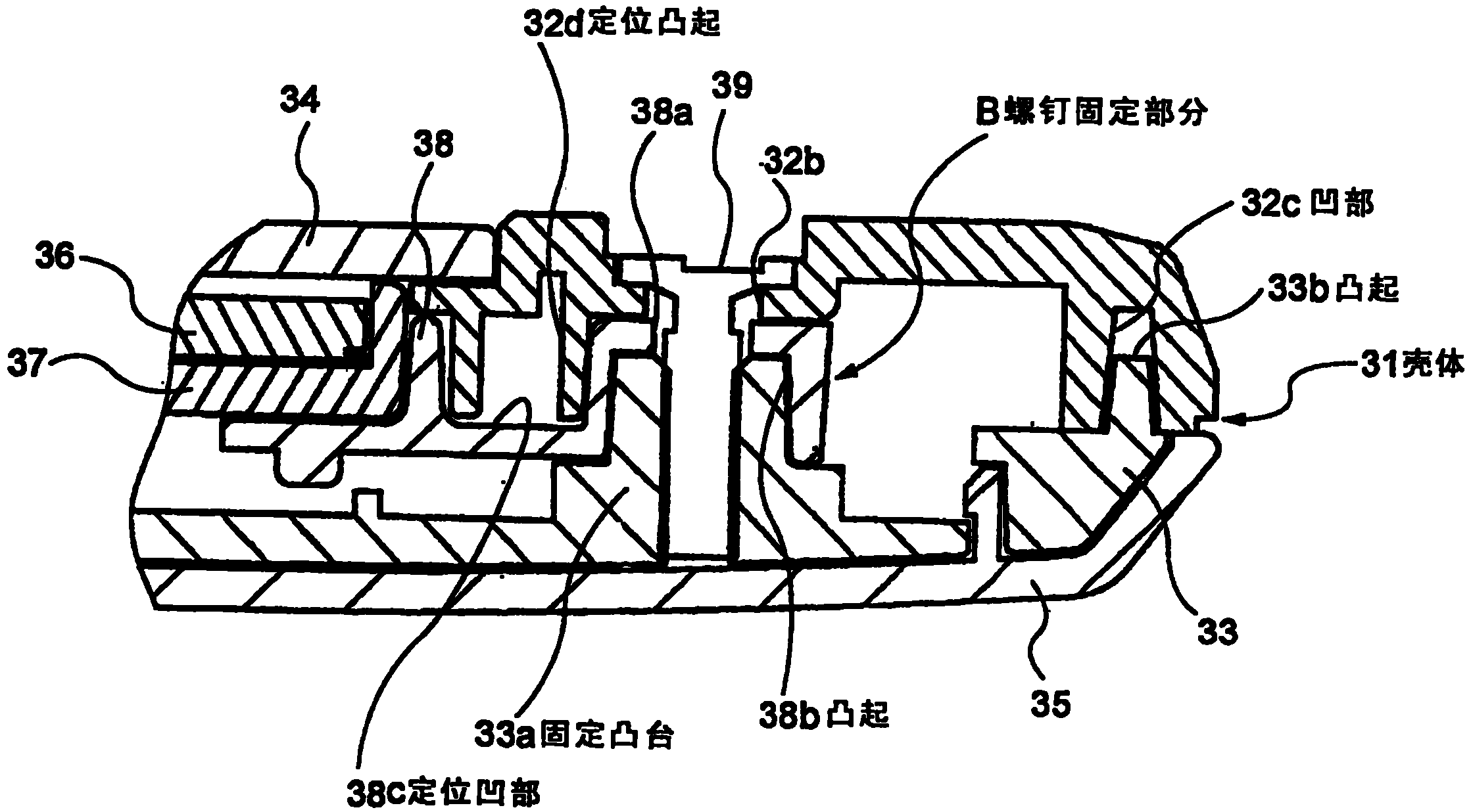
To shown in Figure 5, a plurality of screw part B are formed in the display part 30 as Fig. 2.Each screw part B by be formed on screw insertion hole 32b in the closedtop lid 32, be formed on the screw insertion hole 38a in the built-in framework 38, fixing lug boss 33a and the screw 39 that is formed in the underseal lid 33 formed.Also be, the screw 39 that is inserted among the screw insertion hole 38a of the screw insertion hole 32b of closedtop lid 32 and built-in framework 38 is screwed among the fixing lug boss 33a of underseal lid 33, thereby closedtop lid 32 and underseal lid 33 are fixed together, and simultaneously built-in framework 38 are fixed between closedtop lid 32 and the underseal lid 33 in the mode of uniting clamping.
It is subsidiary that what mention is that in the assembling of display part 30, built-in framework 38 at first is bonded in the closedtop lid 32, then assembles the underseal lid, and last trip bolt 39.
Be assembled together by the protruding 33b that will be formed on the recess 32c on the inner surface that closedtop covers 32 outer ends and be formed on the inner surface that underseal covers 33 outer ends, carry out the location of closedtop lid 32 and underseal lid 33.By underseal is covered 33 fixing lug boss 33a and is integrally formed in being assembled together to lower convexity 38b in the built-in framework 38, carry out the location of underseal lid 33 and built-in framework 38.In addition, by the positioning convex 32d on the inner surface that will be formed on closedtop lid 32 be formed on being assembled together in the built-in framework 38, carry out the location of closedtop lid 32 and built-in framework 38 to upper recess 38c.
The invention is characterized in shape and the layout of positioning convex 32d, below will describe positioning convex 32d in detail.
Shown in Fig. 5 and Fig. 6 A to Fig. 6 H, positioning convex 32d forms the shape of the rib that continues rather than the form of solid pin on assigned direction.For example, positioning convex 32d forms the shape of the hollow box shown in Fig. 6 A (quadrilateral shape).When positioning convex 32d forms this shape, can the open defect such as shrinkage takes place in suppressing closedtop lid 32 molded in, improve the intensity of positioning convex 32d.As a result, concentrate with opposing stress, can prevent because of such as falling breaking of positioning convex 32d that the impact that causes brings by giving the sufficiently high intensity of the protruding 32d in location.
Preferably form positioning convex 32d by the rib that on both direction, continues at least.The shape that can exemplify has, the L shaped structure shown in cross (X-shaped structure), Fig. 6 E, the ∏ shape shown in Fig. 6 F shown in the hollow circular shown in the example quadrilateral shape, the three-pointed hollow star shown in Fig. 6 B, Fig. 6 C as shown in Figure 6A, Fig. 6 D construct and Fig. 6 G shown in the combination of L shaped structure.When the part of positioning convex 32d has such shape, can obtain the intensity that bigger geometrical moment of inertia also can improve positioning convex 32d.
In addition, the rib that is preferably continued by the mode with ring-type forms positioning convex 32d.The shape that can exemplify has, the hollow circular shown in example quadrilateral shape, the three-pointed hollow star shown in Fig. 6 B and Fig. 6 C as shown in Figure 6A.When the part of positioning convex 32d has such shape, further increased geometrical moment of inertia and can improve the intensity of positioning convex 32d.
Preferably the head portion at rib is formed with curved surface or inclined surface (inclined-plane), and it can guide and be assembled among the location indentations 38c.This is convenient to be assembled together location indentations 38c and positioning convex 32d and can to improve the assembling performance of display part 30.
It is subsidiary that what mention is that the shape of location indentations 38c is not concrete to be limited, as long as this shape allows to be assembled on the positioning convex 32d.The shape of location indentations 38c can be following such shape: the shape that cooperates along the whole profile of the positioning convex 32d shown in Fig. 6 A to Fig. 6 C, or the shape that partly cooperates along the profile of the positioning convex 32d shown in Fig. 6 D to Fig. 6 H.
Preferably positioning convex 32d be arranged in screw part B near.By such layout positioning convex 32d, because when falling the impact that causes and be out of shape, reduce stress on positioning convex 32d and concentrate also and can prevent breaking of positioning convex 32d when closedtop lid 32 and built-in framework 38.
When positioning convex 32d is arranged near screw part B, can be with the screw insertion hole 32b of the location of accuracy preferably closedtop lid 32 and the screw insertion hole 38a of built-in framework 38, thus and therefore can solve screw 39 and become during fastening and tilt to cause the not exclusively fastening problem and the fastening force of screw 39 to be applied to the problem that on the positioning convex 32d positioning convex 32d is broken.
Portable phone according to this embodiment that as above constructs, be assembled together in the location of the closedtop lid 32 that carries out and built-in framework 38 by being formed on the location indentations 38c in the built-in framework 38 and being formed on positioning convex 32d on the inner surface of closedtop lid 32, owing to form positioning convex 32d by rib, do not cause the defective appearance in the closedtop lid 32 so can improve the intensity of positioning convex 32d.As this result, concentrate with opposing stress by giving the sufficiently high intensity of the protruding 32d in location, can prevent positioning convex 32d because breaking of falling etc.
When forming positioning convex 32d, can improve the intensity of positioning convex 32d as the cross sectional shape of positioning convex 32d by adopting quadrilateral shape, three-pointed hollow star, hollow circular, cross, X-shaped structure, L shaped structure, ∏ shape structure and C shape structure or the like by the rib that on both direction, continues at least.
When the rib that is continued by the mode with ring-type forms positioning convex 32d, can by adopt quadrilateral shape, three-pointed hollow star, hollow circular, or the like further improve the intensity of positioning convex 32d as the cross sectional shape of positioning convex 32d.
When positioning convex 32d is arranged in when the built-in framework 38 of major general is fixed near screw part B of closedtop lid 32, can be subjected to concentrating at positioning convex 32d by the stress that reduces on positioning convex 32d when falling the impact that causes.In addition, because can locate the screw insertion hole 32b of closedtop lid 32 and the screw insertion hole 38a of built-in framework 38 with pinpoint accuracy, so can also solve during fastening screw 39 becomes to tilt and the fastening force of screw 39 acts on the positioning convex 32d problem that causes positioning convex 32d to break.
When forming guiding in the head portion of the rib that is constituting positioning convex 32d and be assembled to the curved surface of location indentations 38c or inclined surface, this conveniently is assembled together location indentations 38c and positioning convex 32d, and therefore can improve the assembling performance of portable phone.
It is subsidiary that what mention is that the present invention can't help the foregoing description and limits.
For example, though in the above-described embodiments, positioning convex is formed in the capping that closedtop covers and fixing lug boss is formed on, and positioning convex can be formed in the identical capping with fixing lug boss.
Though in the above-described embodiments, positioning convex is arranged near the inboard of screw part, and positioning convex can be arranged near near or its outside of left side and right side screw part.
Though in the above-described embodiments, with the mode of uniting clamping with built-in frame fixation between the capping of closedtop lid and bottom, built-in framework can screw thread be fixed to one of closedtop lid and bottom capping and positioning convex can be arranged in the screw part near.
Though in the above-described embodiments, portable phone is used as example, and positioner of the present invention (localization method) also can use in the mobile communication terminal neutralization that is different from portable phone and be different from the equipment of mobile communication terminal.
Be assembled in the location indentations that is formed in the combined member by the positioning convex that will be formed on the shell inner surface, the present invention can be applied to the equipment of the location of carrying out housing and combined member.Particularly, the present invention can also use in may being subjected to such as the mobile communication terminal that falls the impact that causes.