CN1703154A - Sliders for reclosable containers - Google Patents
Sliders for reclosable containers Download PDFInfo
- Publication number
- CN1703154A CN1703154A CNA028245024A CN02824502A CN1703154A CN 1703154 A CN1703154 A CN 1703154A CN A028245024 A CNA028245024 A CN A028245024A CN 02824502 A CN02824502 A CN 02824502A CN 1703154 A CN1703154 A CN 1703154A
- Authority
- CN
- China
- Prior art keywords
- sliding part
- pair
- footing
- type bar
- fastening type
- Prior art date
- Legal status (The legal status is an assumption and is not a legal conclusion. Google has not performed a legal analysis and makes no representation as to the accuracy of the status listed.)
- Pending
Links
Images


Classifications
-
- B—PERFORMING OPERATIONS; TRANSPORTING
- B65—CONVEYING; PACKING; STORING; HANDLING THIN OR FILAMENTARY MATERIAL
- B65D—CONTAINERS FOR STORAGE OR TRANSPORT OF ARTICLES OR MATERIALS, e.g. BAGS, BARRELS, BOTTLES, BOXES, CANS, CARTONS, CRATES, DRUMS, JARS, TANKS, HOPPERS, FORWARDING CONTAINERS; ACCESSORIES, CLOSURES, OR FITTINGS THEREFOR; PACKAGING ELEMENTS; PACKAGES
- B65D33/00—Details of, or accessories for, sacks or bags
- B65D33/16—End- or aperture-closing arrangements or devices
- B65D33/25—Riveting; Dovetailing; Screwing; using press buttons or slide fasteners
- B65D33/2508—Riveting; Dovetailing; Screwing; using press buttons or slide fasteners using slide fasteners with interlocking members having a substantially uniform section throughout the length of the fastener; Sliders therefor
- B65D33/2541—Riveting; Dovetailing; Screwing; using press buttons or slide fasteners using slide fasteners with interlocking members having a substantially uniform section throughout the length of the fastener; Sliders therefor characterised by the slide fastener, e.g. adapted to interlock with a sheet between the interlocking members having sections of particular shape
-
- A—HUMAN NECESSITIES
- A44—HABERDASHERY; JEWELLERY
- A44B—BUTTONS, PINS, BUCKLES, SLIDE FASTENERS, OR THE LIKE
- A44B19/00—Slide fasteners
- A44B19/24—Details
- A44B19/26—Sliders
- A44B19/267—Sliders for slide fasteners with edges of stringers having uniform section throughout the length thereof
-
- Y—GENERAL TAGGING OF NEW TECHNOLOGICAL DEVELOPMENTS; GENERAL TAGGING OF CROSS-SECTIONAL TECHNOLOGIES SPANNING OVER SEVERAL SECTIONS OF THE IPC; TECHNICAL SUBJECTS COVERED BY FORMER USPC CROSS-REFERENCE ART COLLECTIONS [XRACs] AND DIGESTS
- Y10—TECHNICAL SUBJECTS COVERED BY FORMER USPC
- Y10T—TECHNICAL SUBJECTS COVERED BY FORMER US CLASSIFICATION
- Y10T24/00—Buckles, buttons, clasps, etc.
- Y10T24/15—Bag fasteners
-
- Y—GENERAL TAGGING OF NEW TECHNOLOGICAL DEVELOPMENTS; GENERAL TAGGING OF CROSS-SECTIONAL TECHNOLOGIES SPANNING OVER SEVERAL SECTIONS OF THE IPC; TECHNICAL SUBJECTS COVERED BY FORMER USPC CROSS-REFERENCE ART COLLECTIONS [XRACs] AND DIGESTS
- Y10—TECHNICAL SUBJECTS COVERED BY FORMER USPC
- Y10T—TECHNICAL SUBJECTS COVERED BY FORMER US CLASSIFICATION
- Y10T24/00—Buckles, buttons, clasps, etc.
- Y10T24/25—Zipper or required component thereof
- Y10T24/2532—Zipper or required component thereof having interlocking surface with continuous cross section
- Y10T24/2534—Opposed interlocking surface having dissimilar cross section
Landscapes
- Engineering & Computer Science (AREA)
- Mechanical Engineering (AREA)
- Bag Frames (AREA)
- Slide Fasteners (AREA)
Abstract
A flexible reclosable container including profiles which are locked and unlocked by a slider . One embodiment of the slider has a pair of feet which extend from one end of the slider to the other end and which resist pulling of the slider off of the profiles. Another embodiment of the slider has three spaced pairs of feet which resist removal of the slider from the profiles. The slider in one embodiment has an enlarged central portion which facilitates grasping the slider and is easy to manufacture by die casting.
Description
Technical field
The present invention relates to the container of Reclosable, especially relate to the fastener strips and the sliding part of the container that is used for flexible Reclosable, and require the priority of the U.S. Provisional Patent Application No.60/330140 of application on October 17 calendar year 2001.
Background technology
A kind of container of flexible Reclosable comprises the type bar, uses and can lock and open the type bar along the transportable sliding part of this type bar.The occasion that the container of this Reclosable is used in formation, fills and seal, wherein product is packaged in this container in advance or is contained in this container and sold; Also can be used in the occasion of container being sold client, client uses the article that this container is packed needs parcel.No matter how this container uses or uses, and all needs sliding part and type bar to be configured to like this, can prevent that sliding part from taking off from the type bar easily that is:.Sliding part is relatively cheap and be easy to make also and need.
Summary of the invention
An embodiment of the sliding part of the fastening type bar that is used to lock and open flexible reclosable container of the present invention can comprise body, and it comprises top and pair of sidewalls, and this body has the inside that is limited by top and sidewall.Body also comprises first pair of footing, second pair of footing and the 3rd pair of footing, and all these are used for sliding part is remained on the fastening type bar to footing, and along this type bar guided slidable part.The second pair of footing is positioned between first and the 3rd pair of footing and is spaced apart with first and the 3rd pair of footing.
Another embodiment of the present invention comprises pair of fastener strips, and each fastener strips has the sidewall that has top.But this fastener strips comprises a pair of relative interlocking type bar element, and they protrude and be configured for repeatedly locking and opening fastener strips from the sidewall of fastener strips.Each fastener strips has the flange that begins to extend from the contiguous position on the top of fastener strips separately.Also comprise sliding part, the separator that it has top and paired opposing sidewalls and is used for type bar element is opened.This top has relative both sides and the middle body between them.This sidewall dangles downwards from the relative both sides at top.Separator dangles downwards and has first from the middle body at top, and this first has first width that is configured for opening type bar element.This separator also has first is connected to second portion on the top, and described second portion has second width less than first width.When type bar element was interlocked, flange was adjacent to each other; But flange also can slide between top and first, and when separator was opened type bar element, it can be through the coupling part.
An embodiment more of the present invention is the sliding part of fastening type bar that is used for locking and open the container of flexible Reclosable, and it comprises the body with top and pair of sidewalls.This body has the inside that is limited by top and sidewall, and have along with the first size of type bar equidirectional.This body also comprises a pair of footing, and they remain on sliding part on the fastening type bar and along fastening type bar and guide this sliding part.This body also comprises and is used for separator that type bar element is opened, and this separator is contained on the top, extend into inside and prolong the whole first size of described body.
An embodiment more of the present invention is the sliding part of fastening type bar that is used for locking and open the container of flexible Reclosable.This sliding part comprises the body with top and pair of sidewalls, and this body has the inside that is limited by top and sidewall, and have open the end and closing end.This body also comprises a pair of footing, and they remain on sliding part on the fastening type bar and along fastening type bar and guide this sliding part.This is held from opening of body footing and extends to closing end.This body also comprises the separator that dangles from the top downwards and begins to projecting inward a pair of closing bars from sidewall, and closing bars is spaced apart along downward direction and separator.
An embodiment more of the present invention is the sliding part of fastening type bar that is used for locking and open the container of flexible Reclosable.This sliding part has opens end and closing end.This body comprises top cross part and the pair of sidewalls that is coupled together by this lateral part at closing end.This lateral part has internal vertical walls.Each sidewall has from the vertical wall of described lateral part and extends to the described passage of opening end.Also be provided with closing bars, it is contained on the sidewall of closing end and to the inside of sliding part and extends.This sliding part also comprises the top that is slidingly received in this passage, and described top has dress and extends to open the separator of fastening type bar thereon and between sidewall.
An embodiment more of the present invention relates to the sliding part of the fastening type bar of the container that is used for locking and open flexible Reclosable.This sliding part comprises the body with top and pair of sidewalls.This body has the inside that is limited by top and sidewall, and also have open the end and closing end.This body also comprises a pair of footing, and they remain on sliding part on the fastening type bar and along fastening type bar and guide this sliding part.This body also comprise the separator that dangles from the top downwards and from sidewall to projecting inward a pair of closing bars.This closing bars is spaced apart along downward direction and separator, and spaced apart along direction that makes progress and footing.
An embodiment more of the present invention is the sliding part of fastening type bar that is used for locking and open the container of flexible Reclosable.This sliding part comprises the body with top and pair of sidewalls, and this body has the inside that is limited by top and sidewall, and also have open the end and closing end.This body also comprises a pair of footing, is used for sliding part remained on the fastening type bar and along fastening type bar guiding this sliding part.This is held from opening of body footing and extends to closing end.This body also comprise the separator that dangles from the top downwards and from sidewall to projecting inward a pair of closing bars, this closing bars is spaced apart along downward direction and separator, and spaced apart along direction that makes progress and footing.
Description of drawings
By reading the detailed description of carrying out below with reference to accompanying drawing, other purposes of the present invention and advantage will become clear.Wherein:
Figure 1A is the side view of flexible according to an embodiment of the invention Reclosable container.
Figure 1B is the profile along the device of direction of arrow Figure 1A of seeing over of Figure 1A center line 1B-1B.
Fig. 2 is the vertical view of sliding part according to an embodiment of the invention.
Fig. 3 is the end-view along the device of direction of arrow Fig. 2 of seeing over of Fig. 2 center line 3-3.
Fig. 4 is the upward view along the device of direction of arrow Fig. 2 of seeing over of Fig. 3 center line 4-4.
Fig. 5 is the side view along the device of Fig. 2 center line 5-5 Fig. 2 of seeing over.
Fig. 6 is the vertical view of sliding part according to another embodiment of the present invention.
Fig. 7 is the end-view along the device of direction of arrow Fig. 6 of seeing over of Fig. 6 center line 7-7.
Fig. 8 is the upward view along the device of direction of arrow Fig. 6 of seeing over of Fig. 7 center line 8-8.
Fig. 9 is the side view along the device of direction of arrow Fig. 6 of seeing over of Fig. 6 center line 9-9.
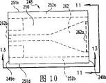
Figure 10 is the vertical view of sliding part according to another embodiment of the present invention.
Figure 11 is the end-view along the device of direction of arrow Figure 10 of seeing over of Figure 10 center line 11-11.
Figure 12 is the upward view along the device of direction of arrow Figure 10 of seeing over of Figure 11 center line 12-12.
Figure 13 is the side view along the device of direction of arrow Figure 10 of seeing over of Figure 10 center line 13-13.
Figure 14 is the vertical view of sliding part body according to another embodiment of the present invention.
Figure 15 is the end-view along the device of direction of arrow Figure 14 of seeing over of Figure 14 center line 15-15.
Figure 16 is the upward view along the device of direction of arrow Figure 14 of seeing over of Figure 15 center line 16-16.
Figure 17 is the side view along the device of direction of arrow Figure 14 of seeing over of Figure 14 center line 17-17.
Figure 18 is the vertical view at removable sliding part top, and this sliding part top can be used with the sliding part body of Figure 14 according to an embodiment of the invention.
Figure 19 is the end-view along the device of direction of arrow Figure 18 of seeing over of Figure 18 center line 19-19.
Figure 20 is the upward view along the device of direction of arrow Figure 18 of seeing over of Figure 19 center line 20-20.
Figure 21 is the side view along the device of direction of arrow Figure 18 of seeing over of Figure 18 center line 21-21.
Figure 22 A is the vertical view according to two sliding parts of one embodiment of the invention assembling.
Figure 22 B sees over the end-view of sliding part of Figure 22 A along the direction of arrow of Figure 22 A center line 22B-22B.
Figure 23 is the vertical view at removable according to another embodiment of the present invention sliding part top.
Figure 24 is the end-view of the device of Figure 23.
Figure 25 is the side view of the device of Figure 23.
Figure 26 is the vertical view of sliding part body according to another embodiment of the present invention.
Figure 27 is the vertical view at removable according to another embodiment of the present invention sliding part top.
Figure 28 is the end-view of sliding part according to another embodiment of the present invention.
Figure 29 is the end and the bottom perspective view of sliding part according to another embodiment of the present invention.
Figure 30 is the bottom and the end perspective view of the sliding part of Figure 29.
Figure 31 is the end and the top perspective of the sliding part of Figure 29.
Figure 32 is the end and the bottom perspective view of the sliding part of Figure 29.
Figure 33 is the end-view of sliding part that comprises Figure 29 of some exemplary dimensions.
Figure 34 is seen over and comprises the upward view of sliding part of Figure 33 of some exemplary dimensions along the direction of arrow of Figure 33 center line 34-34.
Figure 35 is the profile of another embodiment that is used for the fastening type bar of the Reclosable container that the type bar opens.
Figure 36 is the profile similar to Figure 1B of fastening type bar, and Figure 36 shows the type bar that combines with the sliding part of Figure 37-42.
Figure 37 is the perspective view that forms the sliding part of another embodiment of the present invention.
Figure 38 is another perspective view of the sliding part of Figure 37.
Figure 39 be Figure 37 of cutting open along the direction of arrow of the line 39-39 of Figure 40 and 38 sliding part cut open picture.
Figure 40 is the front view of the closing end of this sliding part.
Figure 41 is the profile of cutting open along the direction of arrow of the line 41-41 of Figure 40.
Figure 42 is the vertical view of the sliding part of Figure 37-41.
The specific embodiment
In order to promote understanding, with reference now to embodiment illustrated in the accompanying drawings and use specific language to be described to the principle of the invention.It should be understood that, be not to want to limit the scope of the invention at this, and change and further improve and the further application of principle of the present invention at these of the device shown in this, as the technical staff who the present invention relates to the field usually expectation.
Figure 1A shows the container 20 of the flexible Reclosable that is used for holding product, and this container 20 is used for forming, filling and seal with commodity, also can be used as empty container and sells.Container 20 comprises first and second sidewalls 22 and 24, and they can be made by any suitable thermoplastic film respectively, for example low density polyethylene (LDPE), LLDPE or materials similar.Sidewall 22,24 comprises first left cross side the sealing 28 and second right cross side sealing 30.Container 20 also comprises usually and a pair of interlocking fastener strips 32 and 34 relative bottom margins 26.Bottom margin 26 can be included in the broken line between sidewall 22 and 24, for example be used to use the container of vertical forming, filling and sealing device formation, perhaps the edge 26 of another form can be included in the seal between sidewall 22 and 24, for example is used for the container 20 that usage level moulding, filling and sealing device form.
The interlocking tape 32 of fastening type bar and 34 extends along the top of container 20. Tape 32 and 34 is sealed in end stop 36 and 38 places.The docking station 39 that forms is positioned near the end stop 36.As the replacement form of implementation of the docking station that forms, tape 32 and 34 also can comprise one or more vertical incision 37a and/or 37b, as described in the back.Tape 32 and 34 seals mutually and seals at angle sealing 40 and 42 place's oppose side walls 22 and 24.Angle sealing 40 and 42 is along each location, edge of container 20.The sealing 40 and 42 lay respectively at usually fastener strips 32 and 34 shoulder 45 and 47 below.
In one embodiment of this invention, container 20 is included in showing between sidewall 22 and 24 and surreptitiously opens sealing (tamper-evident seal) 43.Sealing 43 can be the extension of the interlocking tape of the opening of crossing container 20 that extends internally.Sealing 43 can be one-body molded with this tape, above perhaps appending to separately.The sealing 43 break or the non-state that breaks clearly illustrates for the user: whether container 20 before was opened.Show surreptitiously to open to seal especially and use with food being inserted container 20 interior formation, filling and sealing machines.
With reference to Figure 1A and 1B, sliding part 148 can slide on fastener strips 32 and 34. Fastener strips 32 and 34 comprises a pair of vertical wall portion 80b and 80a respectively.Convex bar element 82b outwards protrudes from the 80b of wall portion.Matrix bar element 82a outwards protrudes from the 80a of wall portion.The sliding part 148 that illustrates is sealed the not interlocking part of fastener strips 34 and 32.Sliding part 148 makes type bar 82a and 82b interlocking along moving of fastener strips, and perhaps type bar 82a and 82b open.Matrix bar 82a comprises upper element 81a, and lower element 81b outwards protrudes bigger amount from tape wall 82a then.Because the length of upper element 81a surpasses 81b, thus in the interlocking process of tape 32 and 34, convex bar element 82b at first with upper element 81a by touching, secondly contact with lower element 81b.In one embodiment of this invention, sliding part 148 comprises the separator 162 apart from middle body 151b one vertical depth, when sliding part 148 along fastener strips when opening direction and move, this degree of depth is enough to element 82a and 82b divided to be opened.The footing 160b of sliding part 148 and 160a remain on the tape of interlocking sliding part by shoulder 45 and 47 respectively.
In another embodiment of the present invention, container 22 comprises one or more vertical incision 37a and 37b, and they pass fastener strips 32 and 34 by the top of fastener strips and extend the still preferred interlocking type bar element of fastener strips that do not pass downwards.Owing to have the sliding part separator, these otch 37a and 37b can reduce to be applied to the stress on the fastener strips when one of sliding part adjacent end stop part.For example, the otch 37b of sack 22 can increase the flexibility at fastener strips top, thereby when sliding part and separator adjacent end stop part 38 berth, can reduce the separating force near the interlocking type bar element the end stop 38.Yet should be understood that not to be that all embodiment of the present invention comprise vertical incision 37a and 37b.For example, in one embodiment of the invention,, can form docking station 39 by sliding part being pressed against on the end stop 36 still plastic after the heating.In this embodiment, do not need otch 37a and 37b and do not have otch.
Fig. 2,3,4 and 5 represents vertical view, end elevation view, upward view and the side view of sliding part 48 according to an embodiment of the invention.Sliding part 48 comprises body 49, and body is preferably by the time of its injection moulding.In one embodiment, sliding part 48 is slidably engaged to a pair of interlocking fastener strips at Figure 1A flexible Reclosable container similar with the container shown in the 1B.As seeing among Fig. 2, body 49 comprises closing end 49a, when sliding part 48 when the closing direction of fastener strips moves, through the fastener strips of this closing end by a pair of interlocking.Body 49 also comprises opens end 49b, when sliding part 48 when the closing direction of this tape moves, open end by a pair of fastener strips of opening through this.
Refer again to Fig. 2 to 5, body 49 also comprises the top 50 with a pair of middle body 51a and 51b, and this middle body laterally crosses relative top 51d from a top 51c.50 edge 51c and 51d dangle downwards from the top respectively for a pair of relative sidewall 52a and 52b.Sidewall 52a and 52b comprise bottom margin 54a and 54b respectively, and they are vertically opposite with top 51c and 51d respectively usually.
This of sliding part be to the shoulder acting in conjunction of footing and fastener strips, thereby keep engaging of sliding part and fastener strips, and then help the guided slidable part to slide along fastener strips.As seeing among Figure 1B, shoulder 45 and 47 lays respectively at by in footing 160b and sidewall 152b and footing 160a and the formed turning of sidewall 152a Colaesce.By shoulder 45 and 47 and the interference of footing 160b and 160a, can stop respectively by any way from the vertical rise of tape 32 sliding part 148 with 34.
Yet shoulder 45 and 47 integrality are subjected to the infringement of other features of container 20 sometimes.With reference to figure 1a, the end stop 36 and 38 that fusion is set at the opposed end place of fastener strips 32 and 34 can make the marginal portion of the marginal portion distortion of shoulder 45 and 47 or excision shoulder 45 and 47.This distortion can weaken makes the sliding part that sliding part engages with sack and the acting in conjunction of footing.For example, move the footing disengaging shoulder that sliding part can cause distal-most end towards end stop 38 as much as possible.On the sliding part that only has two pairs of relative footing, a pair of footing breaks away from shoulder makes sliding part rotate engaging footing around another unintentionally to allow the user, and mentions sliding part from this fastener strips subsequently.Yet sliding part comprises a pair of central footing, for example footing 58a and 58b according to an embodiment of the invention.Even footing 60a and 60b break away from the shoulder of fastener strips, footing 58a of these central authorities and 58b and open bottom pin 56a and 56b still keeps and the engaging of shoulder stop or prevent the rotation of sliding part and pull from this fastener strips subsequently.
With comprise along comparing from those sliding parts of opening the continuous footing on the sidewall length of holding closing end, the gap is set between phase adjacency pair footing allows some embodiments of the present invention to reduce material cost and alleviate sliding part weight.In addition, as seeing in Fig. 2 and 5, the layout in this gap also can help the design and the manufacturing of injecting molding die, and also helps injection moulding processing.For example, gap 59b be positioned at middle body 51a and closing bars 64a and 64b below.Gap 57b be positioned at middle body 51b and separator 62 below.In certain embodiments, sliding part 48 is injection molding in one or two part mould, and these two mould parts are bonded together along vertical direction (with reference to the vertical direction of figure 5).In addition, the spaced apart gap 61b of the middle body 51a at top 50 and 51b.The spaced apart gap 61a of the edge 49a of middle body 51a and body 49.The edge 49b of middle body 51b and body 49 is gap 61c at interval.As seeing among Fig. 5, gap 61a, 61b and 61c and gap 59b and 57b are with being disposed in order of replacing.Therefore, being used for half mould that injection moulding extends the sliding part 48 of (seeing as Fig. 5) downwards comprises solid section corresponding to gap 61a, 61b and 61c.Being used for half mould that injection moulding extends the sliding part 48 of (engaging with half mould on top) vertically upward comprises the solid section in gap 57b and 59b usually.
With reference to figure 2,3,4 and 5, sliding part 48 comprises triangle or wedge-shaped separator 62 again, and it extends downwardly into inner 55 from middle body 51b.Separator 62 comprises narrow 62b, when sliding part along fastener strips when separator moves, this narrow begin with the interlocking the type bar open.A pair of closing bars 64a and 64b protrude downwards from middle body 51a.Closing bars 64a and 64b are fit to and are constructed to be permeable to and interlock fastener strips sliding between closing bars.
Fig. 6,7,8 and 9 shows vertical view, end elevation view, upward view and the side view of sliding part according to another embodiment of the present invention.Be meant such element in hundred prefixes of the preceding use of element number (XX) " N " (NXX), that is: except the difference that below will describe and illustrate, this element is components identical with the element that does not have prefix (XX) of before having described or having illustrated.
Sliding part 148 is identical with sliding part 48 basically, and difference is that separator is connected to mode on the middle body at top.With reference to figure 9, triangle or wedge-shaped separator 162 divide 163 to be connected on the middle body 151b at top 150 by middle interconnecting piece.This coupling part has the width perpendicular to sliding part 148 longitudinal axis less than the separation width 162a of separator 162.The coupling part 163 that illustrates has square cross section, but it can have the cross section of Any shape.Coupling part 163 preferred and separator 162 and the integrally moulded moulding of middle body 151b.
The coupling part that width is reduced is combined in and helps to keep engaging of sliding part 148 and pair of fastener strips on the separator.With reference to Figure 1B, the sliding part 148 that illustrates engages with pair of fastener strips 32 and 34.Each bar fastener strips comprises top flange 84a and 84b respectively, and they inwardly stretch out from the sidewall 80a and the 80b of fastener strips 34 and 32 respectively.When interlock fastener strips, flange 84a and 84b provide the top closure of fastener strips.In addition, top flange 84a and 84b are trapped in the inner space 155 between the lower surface of the top surface of separator 162 and middle body 151b.Flange 84a and 84b extend internally towards the inner space from their sidewalls separately, thereby flange and sidewall are around separator 162.So that flange passes sliding part to slide, the part 163 that can use width to reduce is held this flange by enough horizontal spaces are provided.In addition, any attempt that sliding part 148 is pulled away from sack 122 will cause the top corner of separator 163 and the inner surface of flange to interfere, and increase thus sliding part 148 is connected to power on tape 32 and 34.
Figure 10,11,12 and 13 represents vertical view, end-view, bottom view and the side view of sliding part 248 according to an embodiment of the invention.Sliding part 248 comprises body 249, and it is preferably by the time of its injection moulding.In one embodiment, sliding part 248 is slidably engaged with a pair of fastener strips of interlocking of the container of flexible Reclosable, similar with shown in Figure 1A and the 1B like that.Body 249 comprises closing end 249a, when sliding part 248 when the closing direction of fastener strips moves, the fastener strips of a pair of interlocking is by this closing end.Body 249 also comprises opens end 249b, when sliding part 248 along this tape when opening direction and move, a pair of fastener strips of opening is opened end by this.
With reference to figure 10-13, body 249 also comprises the top 250 with middle body again, and this middle body laterally crosses relative top 251d from a top 251c.250 edge 251c and 251d dangle downwards from the top respectively for a pair of relative sidewall 252a and 252b.Each sidewall 252a and 252b comprise bottom margin 254a and 254b respectively, and they are vertically opposite with top 251c and 251d respectively usually.
Top 250 and sidewall 252a and 252b limit the inside 255 of sliding part 248.From each sidewall 255 protrusions towards inside are a pair of relative footing.As seeing in Figure 11 and 12, from sidewall 252a to projecting inward be footing 256a, from sidewall 252b to projecting inward be footing 256b.Preferably, footing 256a and 256b are along the length of sliding part 248 aligning that faces with each other.
This of sliding part be to the shoulder acting in conjunction of footing and fastener strips, thereby keep engaging of sliding part and fastener strips, and then help the guided slidable part to slide along fastener strips.With reference to Figure 1B, shoulder 45 and 47 lays respectively at unites in the turning that forms and footing 256a and sidewall 252a unite in the turning that forms by footing 256b and sidewall 252b.Respectively by shoulder 45 and 47 with the mutual interference of footing 256a and 256b, can stop any from tape 232 with 234 there with sliding part 248 vertical attempts of mentioning.
Sliding part 248 comprises multiple improvement, and these improvement can reduce the possibility that the user is pulled away from sliding part 248 pair of fastener strips unintentionally.See like that as best among Figure 11 each footing 256a and 256b 250 are inclined upwardly towards the top, between the inner surface of the end face of footing and respective side walls, form angle 256c that spend less than 90.In a more preferred embodiment, angle 256c is less than about 75 degree and greater than about 20 degree.In addition, have the roughly angled foot of linear surfaces although Figure 11 shows, the present invention also plans to use hook-shaped cross, comprises and is cut into part fillet or rounding.
The separator 262 of sliding part 248 comprises head 262b, and it is from surface that the triangle or the wedge-like portion of separator 262 extend to closing end 249a.Extend to range with the head 262b limit slippage part 248 of the flush of closing end 249a.For example, shown in Figure 1A, sliding part 248 contacts with the penetralia melt region of end stop 36 towards the mobile head 262b that causes of end stop 36.This contact has limited the sliding stroke of sliding part 248, make the user spur sliding part 248 difficulty that becomes more of sliding like this, to such an extent as to the part of footing no longer contacts with the shoulder of fastener strips, spur sliding part 248 disengagings thus and become difficult more with engaging of fastener strips 32 and 34.
As seeing in Figure 11 and 13, closing bars 264a and 264b from sidewall 252a and 252b towards inner 255 to projecting inward.Closing bars 264a and 264b preferred vertical are between the end face of the bottom surface of separator 262 and footing 256a and 256b.With reference to Figure 13 (promptly being parallel to the mould pair (dieset) that the fastener strips length direction is linked together), this mode that is arranged vertically helps using the injecting molding die pair that is linked together along the longitudinal axis of sliding part.
As seeing in Figure 11 and 13, sliding part 248 comprises the parts with different vertical direction, thereby a pair of mould that (be that mould combines like this: a mould is close towards begin another close mould from closed side 249a from opening side 249b) along the longitudinal easy to use is linked together carries out injection moulding.In this manner, molded some parts are possible, the interior corners of the inclination of representing with angle 256c for example, and its use approaching mould that is perpendicular to one another is difficult to make.Because directly on the inclined inner surface of footing 256a and 256b, distinguish the blend stop 264a and the 264b of perpendicular alignmnet closure, so can add to the difficulties.On the contrary, in one embodiment of this invention, mould is one another along vertically approaching, and uses the solid section of the complementary shape of vertically approaching mould element, can easily be manufactured on the inner space of the opening under the top of the bottom of closing bars and angled foot again.
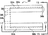
Figure 14-21,22A and 22B show sliding part according to another embodiment of the present invention.These accompanying drawings show two parts of two parts sliding part 348 of Reclosable container.Figure 14-17 expression has the body 349 of pair of sidewalls 352a and 352b.Figure 18-21 expression is slidingly received in the independent molded top 350 in the track 366 of body 349.Figure 22 A and 22B represent the vertical view and the end view of the sliding part 348 assembled respectively.
Figure 14-17 shows the body 349 similar to previously described body 249.Yet body 349 comprises the top cross part 368 that connects sidewall 352a and 352b.Each sidewall 352a and 352b comprise channel part 366a and 366b, and they extend towards the internal vertical walls of top cross part 368 from the surface of opening end 349b.That extend internally from sidewall 352a and 352b is closing bars 364a and 364b, and their function is that the fastener stringer interlocking that will slide between closing bars is lived.
Figure 18-21 shows top 350, and it comprises separator 362, and this separator 362 has the head 362b similar to previously described head 262b.Yet top 350 is fit to and is constructed to be permeable to be slidingly received in passage 366a and the 366b, thereby causes sliding part 348 to be similar to single sliding part 248 substantially.Discerptible top 350 preferably is contained in passage 366a and the 366b in the mode of slight interference fit, thereby rubbing action keeps top 350 to be attached on the body 349.
Figure 22 A and 22B represent the vertical view and the end view of two sliding parts 348 assembling respectively.Insert in passage 366a and the 366b at the top 350 that illustrates.
Figure 23,24 and 25 represents vertical view, end-view and the side view at the separable top 350 ' of sliding part 348 ' respectively.Sliding part 348 ' comprises passage 366a and the interior top 350 ' of 366b that is slidingly received in body 349.Except the bottom surface of separator 362 ' by coupling part 363 ' and sliding part 350 ' separated and be positioned under the bottom surface of sliding part 350 ', top 350 ' was identical with top 350.Coupling part 363 ' has the first width 363a ', and this width is less than the width 362a ' of wedge shape separator 362 '.
Figure 26 and 27 shows body 349 " and separable top 350 ", they can be assembled into sliding part.As seeing among Figure 26, except passage 366a " and 366b " comprise the inner surface of inclination body 349 " identical with body 349.Passage 366a " and 366b " near 349b " the position the most approaching, along with passage towards closing end 349a " extend, the distance between the relative wall of passage increases.Figure 27 represents top 350 ", except this top 350 " be included in respectively in shape and passage 366a " and 366b " the inclined side 351c of inwall complementation " and 351d ", top 350 " identical with top 350.As seeing among Figure 27, top 350 " width towards opening the narrowest of end (promptly contiguous separator 362 " the wideest part), the wideest near the place of closing end (promptly near distractor heads 362b " end).
Top 350 " be slidingly received in body 349 " passage in.When top 350 " the wideest end (perhaps closing end) be pressed into body 349 " the narrowest end (perhaps opening end) time, sidewall 352a " and 352b " separately.At body 349 " two feeder connections on establish introduction chamber or tapered portion.Perhaps, top 350 " the insertion edge can have the bight of taper, as shown in the figure, thereby help to insert expansion with sidewall.After inserting, sidewall 352a " and 352b " flexibly bounce back into their home position, thus with top 350 " locking is on the throne.
Though Figure 14-27 shows the contiguous intrinsic separable top of opening end 349b of insertion, the present invention also comprises suitable and is configured to from opening the separable top of holding the 349a insertion and holding passage.In addition, though illustrated and described separable top about the longitudinal axis symmetry, but the present invention also imagines these separable tops, that is: only a side comprises inclined surface, perhaps comprises some miscellaneous parts that are locked at intrinsic appropriate position with the respective channel acting in conjunction with the top with the location.
Figure 28 represents the end-view of sliding part 248 ' according to another embodiment of the present invention.Except sidewall 252a ' and 252b ' slope inwardly so that near the sidewall bottom of footing 256a ' and 256b ' than towards distance between the sidewall at top 250 ' is narrow, sliding part 248 ' is identical with sliding part 248.Angle 252c ' spends less than 90 between the outer surface of end face 250 ' and sidewall 252a ', and in a preferred embodiment, it is less than about 85 degree and greater than about 60 degree.Angle 252d ' spends less than 90 between the outer surface of end face 250 ' and sidewall 252b ', and in a preferred embodiment, it is less than about 85 degree and greater than about 60 degree.Though illustrated and described the lean-in skew wall portion that has the substantially flat surface, the present invention considers that also wall portion comprises those embodiment rounding, non-planar surfaces.
Figure 29-34 represents the different views of sliding part 448 according to an embodiment of the invention.Sliding part 448 comprises body 449, and this body is preferably by the time of its injection moulding.In one embodiment, sliding part 448 is slidably engaged with a pair of fastener stringer of interlocking of flexible Reclosable container, is similar to such that Figure 1A and 1B demonstrate.Body 449 comprises closing end 449a, when sliding part 448 when the closing direction of fastener stringer moves, the fastener stringer of a pair of interlocking is by this closing end.Body 449 also comprises opens end 449b, and when sliding part 448 during along the opening direction and move of this tape, this opens end to the fastener stringer of opening by this.
Refer again to Figure 29 to 34, body 449 also comprises the top 450 with middle body, and this middle body laterally crosses relative top 451d from a top 451c.450 edge 451c and 451d dangle downwards from the top respectively for a pair of relative sidewall 452a and 452b.Each sidewall 452a and 452b comprise bottom margin 454a and 454b respectively, and they are vertically opposite with top 451c and 451d respectively usually.
Top 450 and sidewall 452a and 452b limit sliding part 248 inside 455.From each sidewall 455 protrusions towards inside are a pair of relative footing.From sidewall 452a to projecting inward be footing 456a, from sidewall 452b to projecting inward be footing 456b.Preferably, footing 456a and 456b are along the length of sliding part 448 aligning that faces with each other.
This of sliding part be to the shoulder acting in conjunction of footing and fastener stringer, thereby keep engaging of sliding part and fastener stringer, and then help the guided slidable part to slide along fastener stringer.With reference to Figure 1B, shoulder 45 and 47 lays respectively at unites in the formed turning and footing 456a and sidewall 452a unite in the formed turning by footing 456b and sidewall 452b.Respectively by shoulder 45 with 47 with the mutual interference of footing 456a and 456b stop any with sliding part 448 by any way from the vertical rise of tape 432 with 434.
Sliding part 448 comprises multiple improvement, and these improvement can reduce the possibility that the user is pulled away from sliding part 448 a pair of fastener stringer unintentionally.As the best among Figure 33 was seen, each footing 456a and 456b comprised upright projection or antelabium 457a and 457b respectively.These protruding 457a and 457b usually extend towards the inside 455 of sliding part 448 from the middle body of the approximate horizontal of footing 456a and 456b respectively.In addition, although Figure 33 shows the acclivitous projection with substantially linear surface, the present invention also comprises the use hook-shaped cross, comprises being cut into part fillet or rounding.
The separator 462 of sliding part 448 comprises head 462b, and it is from surface that the triangle or the wedge-like portion of separator 462 extend to closing end 449a.Extend to range with the head 462b limit slippage part 448 of the flush of closing end 449a.For example, shown in Figure 1A, sliding part 448 contacts with the penetralia melt region of end stop 36 towards the mobile head 462b that causes of end stop 36.This contact has limited the sliding stroke of sliding part 448, make the user spur sliding part 448 difficulty that becomes more of sliding like this, so that the part of footing no longer contacts with the shoulder of fastener stringer, spur sliding part 448 disengagings thus and become difficult more with engaging of fastener strips 32 and 34.
As seeing among Figure 34, closing bars 464a and 464b from vertical mid point of sidewall 452a and 452b towards inner 455 to projecting inward.Closing bars 464a and 464b preferred vertical are between the end face of the bottom surface of separator 462 and footing 456a and 456b, as seeing among Figure 33.This mode that is arranged vertically helps using be used for the injection molding mould pair (i.e. the mould pair that is linked together) that is linked together along the longitudinal axis of sliding part on the direction parallel with fastener strips length.
Sliding part 448 comprises the parts with different vertical direction, thereby a pair of mould that is linked together along the longitudinal easy to use (be that mould combines like this: a mould is from opening side 449b towards close from another close mould of closed side 449a) carries out injection moulding.Like this, molded some parts are possible, and for example the height of the footing between the wall portion inner surface (being respectively 452a and 452b) of inner most projection (457a and 457b) and sliding part body reduces part, and this use approaching mould that is perpendicular to one another is difficult to make.Because direct respectively vertically aligned closing bars 464a and the 464b on the inner surface of footing 456a and 456b is so can add to the difficulties.On the contrary, in one embodiment of this invention, mould is one another along vertically approaching, and the solid section of the complementary shape by vertically approaching mould element can easily be manufactured on the inner space of the opening under the top of the bottom of closing bars and angled foot again.
Sliding part 448 also comprises external component, and they provide more sensation and the improved promptly surface of determining for the user, and no matter sliding part is along opening direction or closing direction moves.That sliding part 448 comprises inclination or moulding outer surface 472a and 472b, when this outer surface from closing end 449a when vertically cross at the middle part of sliding part body 449, they stretch out away from inner 455.Similarly, the sliding part body other half comprise 452a of wall portion and 452b, they comprise along from open end 449b towards the direction of sliding part body mid point away from inner 455 outer surface 470a and the 470b that extend.The joint of outer surface 470a and 472a is joined along the substantially vertical 474a of spine, and this spine is preferably near the mid point along the length of body 449.The joint of outer surface 470b and 472b is joined along the substantially vertical 474b of spine, and this spine is preferably near the mid point along the length of body 449.
As the best among Figure 34 is seen, compare with other points along vertical wall 452a and 452b, 474a of spine and 474b are farther apart from the center line of body 449b.These central spine and inclination or crooked outer wall make the user can firmly grasp and control sliding part more easily.For example, when when the direction that makes type bar interlocking moves sliding part, the user can be placed on his finger on the wall surface 472a and 472b of outside enlarging, and push 474a of spine and 474b lightly, they can more easily be caught and be needed littler mantle friction than other smooth plane outside wall surface.As another example, when when the direction of opening the type bar moves sliding part, the user can be placed on his finger on the wall surface 470a and 470b of outside enlarging, and push 474a of spine and 474b lightly, they can be caught more easily and be needed littler mantle friction than other smooth plane outside wall surface.
In one embodiment, the present invention includes the device that is used for the Reclosable container, this device comprises pair of fastener strips, each tape has the sidewall that has the top, but this fastener strips comprises a pair of relative interlocking type bar element, and they protrude and be fit to and be constructed to be permeable to repeat locking and open this fastener strips from the sidewall of fastener strips.Each fastener strips has the flange that begins to extend from the position at contiguous corresponding fastener strips top.This device also comprises sliding part, and it comprises: body, body comprise the top with a pair of relative side and the middle body between them; A pair of relative sidewall; And the separator that is used for opening type bar element.Each sidewall dangles downwards from the opposite edges at top.This separator begins to dangle downwards from the middle body at top, and has the first that is fit to and is configured to open type bar element, and it has first width.By coupling part separator is connected to the top with second width littler than first width.When sliding part was connected on the fastener strips, at least one flange can slide between the top of body and first, and also can pass through this coupling part.When the type bar was interlocked, flange preferably overlapped each other.
In another embodiment, but the present invention includes the sliding part of locking and opening the fastening type bar of flexibility closed container, this sliding part comprises the body with top and a pair of opposing sidewalls.Each sidewall dangles downwards from the top and has and the isolated bottom margin in top.Body has the inside that is limited by top and sidewall.This device also comprises first pair of footing, is used for remaining on sliding part on the fastening type bar and the guided slidable part moves along fastening type bar, and each in the first pair of footing is protruded towards inside from different sidewalls along bottom margin.This device comprises second pair of footing, is used for remaining on sliding part on the fastening type bar and the guided slidable part moves along fastening type bar, and each in the second pair of footing is protruded towards inside from different sidewalls along bottom margin.This device comprises the 3rd pair of footing, is used for remaining on sliding part on the fastening type bar and the guided slidable part moves along fastening type bar, and each in the 3rd pair of footing is protruded towards inside from different sidewalls along bottom margin.The second pair of footing separates respectively between the first pair of footing and the 3rd pair of footing and with them along bottom margin.This device preferably includes a pair of closing bars, and each bar closing bars protrudes and be positioned at the centre at top and relative bottom edge towards inside from different sidewalls.Closing bars along corresponding sidewall between the first pair of footing and the second pair of footing.In preferred first pair of footing each toward each other, each in the second pair of footing toward each other, each in the 3rd pair of footing is toward each other.
With reference now to Figure 35-42,, shows an embodiment more of the present invention at this.With particular reference to Figure 36, represent the profile of the sliding part 548 similar to Fig. 1 b, this sliding part can slide on fastener strips 532 and 534.With regard to structure and the operation that the embodiment of Figure 35-42 adopts, content shown with reference to Figure 1A above and that describe also is suitable.
With reference to Figure 36, sliding part 548 can slide on fastener strips 532 and 534.Fastener strips 532 and 534 comprises a pair of vertical wall 580a and 580b respectively.Convex bar 582b outwards protrudes from wall 580a.Matrix bar element 582a outwards protrudes from wall 580b.The sliding part 548 that illustrates is containing the not interlocking part of fastener strips 534 and 532.Sliding part 548 makes type bar 582a and 582b interlocking along fastener strips mobile, and perhaps type bar 582a and 582b open.Matrix bar 582a comprises upper element 581a and lower element 581b.Sliding part 548 comprises the separator 562 apart from middle body 551b one vertical depth, and when sliding part 548 during along the opening direction and move of fastener strips, this degree of depth is enough to make element 582a and 582b to divide to open.The footing 560b of sliding part 548 and 560a remain on the tape of interlocking sliding part 548 by shoulder 545 and 547 respectively.
With reference to figure 37-42, sliding part 548 comprises body 549, and this body is preferably by the time of its injection moulding.Body 549 comprises closing end 549a, and as shown in Fig. 1 a, the interlocking fastener strips of flexible Reclosable container is by this closing end.When sliding part 548 when the closing direction of this fastener strips moves, the type bar of this interlocking comes up from closing end 549a.Body 549 also comprises opens end 549b, and when sliding part 548 during along the opening direction and move of this tape, this opens end to the fastener strips of opening by this.
Sliding part 548 also comprises separator 562, and as shown in Figure 38,39,40 and 41, separator 562 to small part has the part 562a and the part 562b straight or elongation of wedge shape or rhombus.This separator 562 is fit to and is configured to like this, that is: as shown in figure 36, when sliding part on the fastener strips when opening direction and move, separator can be opened and branch open form bar.Being contained on sidewall 552a and the 552b is on closing bars 564a and the 564b, and they are fit to and are configured to make interlock fastener strips sliding between closing bars.
Sliding part 548 comprises the parts with different vertical direction, thereby a pair of mould that is linked together along the longitudinal easy to use (be that mould combines like this: mould from closed side 549a towards close from opening another close mould of side 549b) carries out injection moulding.Be provided with pair of notches 570, when sliding part being sent into the parts feeder so that be assembled on the fastener strips, otch helps making the sliding part location.
Though in the specification of accompanying drawing and front, be shown specifically and described the present invention; but should think they only be exemplary and be not have restricted; should understand; the just preferred embodiment that has illustrated and described also needs protection and drops on all interior changes and improvements of spiritual scope of the present invention.In claims of back, vertical, level, top and similar term is not as absolute implication, but as relative implication, thereby the different elements in claims is positioned relative to each other.
Claims (27)
1, a kind of sliding part that is used to lock and open the fastening type bar of flexible reclosable container, it comprises:
(a) body, it comprises top and pair of sidewalls, this body has the inside that is limited by top and sidewall;
(b) described body also comprises first pair of footing, is used for remaining on sliding part on the fastening type bar and along this fastening type bar guided slidable part;
(c) described body also comprises second pair of footing, is used for remaining on sliding part on the fastening type bar and along this fastening type bar guided slidable part;
(d) described body also comprises the 3rd pair of footing, is used for remaining on sliding part on the fastening type bar and along this fastening type bar guided slidable part;
(e) described second pair of footing is positioned between first and the 3rd pair of footing and is spaced apart with first and the 3rd pair of footing.
2, sliding part as claimed in claim 1 is characterized in that, described top has first gap, second gap and third space; Described first gap vertically is positioned on described first pair of footing; Described second gap vertically is positioned on described second pair of footing; Described third space vertically is positioned on described the 3rd pair of footing.
3, sliding part as claimed in claim 2 is characterized in that, also comprises separator and a pair of closing bars, described top forms two parts, these two parts are separated by described second gap, and described separator is contained on one of described part, and described closing bars is contained on another described part.
4, sliding part as claimed in claim 3, it is characterized in that, sliding part can be formed by the mould that is engaged with each other that vertically moves by a pair of, very close to each other or the groove of described sliding part, when described mould was engaged with each other with the formation sliding part, this gap or groove were not filled by described mould.
5, a kind of container of Reclosable comprises:
(a) pair of fastener strips, each fastener strips has the sidewall that has top, but described fastener strips comprises a pair of relative interlocking type bar element, they protrude and are constructed to be permeable to repeatedly lock and open fastener strips from the sidewall of fastener strips, and each fastener strips has the flange that extends from the position on the top of contiguous corresponding fastener strips;
(b) sliding part, it comprises the top, the separator that a pair of opposing sidewalls and being used for is opened type bar element, described top has relative both sides and the middle body between them, described sidewall dangles downwards from the two opposite sides at described top, and described separator dangles downwards and has first from the middle body at top, described first has first width and is constructed to be permeable to open this type bar element, described separator has first is connected to second portion on this top, and described second portion has second width less than described first width;
(c) described flange is adjacent to each other when type bar element is interlocked, but described flange can slide between top and first, and when described separator was opened this type bar element, it can pass through described coupling part.
6, the container of Reclosable as claimed in claim 5 is characterized in that, described sliding part also comprises:
(a) first pair of footing is used for remaining on sliding part on the fastening type bar element and along this fastening type bar element guided slidable part;
(b) second pair of footing is used for remaining on sliding part on the fastening type bar element and along this fastening type bar element guided slidable part;
(c) the 3rd pair of footing is used for remaining on sliding part on the fastening type bar element and along this fastening type bar element guided slidable part; And
(d) described second pair of footing is positioned between first and the 3rd pair of footing and is spaced apart with first pair and the 3rd pair of footing.
7, a kind of sliding part of fastening type bar of the container that is used for locking and open flexible Reclosable is characterized in that it comprises:
(a) comprise the body of top and pair of sidewalls, described body has the inside that is limited by top and sidewall, and along having first size with described type bar equidirectional;
(b) described body also comprises a pair of footing, is used for this sliding part remained on the fastening type bar and along this fastening type bar guiding described sliding part; With
(c) described body also comprises and is used for separator that type bar element is opened, and described separator is contained on the described top and extends into described inside and extend the whole first size of described body.
8, the container of Reclosable as claimed in claim 7 is characterized in that, described sliding part also comprises:
(a) first pair of footing is used for remaining on sliding part on the fastening type bar and along this fastening type bar guided slidable part;
(b) second pair of footing is used for remaining on sliding part on the fastening type bar and along this fastening type bar guided slidable part;
(c) the 3rd pair of footing is used for remaining on sliding part on the fastening type bar and along this fastening type bar guided slidable part; And
(d) described second pair of footing is positioned between first and the 3rd pair of footing and is spaced apart with first and the 3rd pair of footing.
9, a kind of sliding part of fastening type bar of the container that is used for locking and open flexible Reclosable, it comprises:
(a) comprise the body of top and pair of sidewalls, described body has the inside that is limited by top and sidewall, and described body has opens end and closing end;
(b) described body also comprises a pair of footing, is used for sliding part remained on the fastening type bar and along this fastening type bar guiding described sliding part, and described this extends to closing end to footing from the end of opening of described body; And
(c) described body also comprise the separator that dangles from described top downwards and from described sidewall to projecting inward a pair of closing bars, described closing bars is spaced apart along downward direction and described separator.
10, sliding part as claimed in claim 9 is characterized in that, described separator extends to the described end of opening from described closing end.
11, sliding part as claimed in claim 9 is characterized in that, described footing is spaced apart along downward direction and described separator and described closing bars.
12, sliding part as claimed in claim 11, it is characterized in that, it can be formed by a pair of mould that is engaged with each other by the along continuous straight runs motion, very close to each other or the groove of described sliding part, when described mould was engaged with each other with the formation sliding part, this gap or groove were not filled by described mould.
13, sliding part as claimed in claim 9 is characterized in that, described footing extends internally with the angle less than 90 degree from described sidewall.
14, sliding part as claimed in claim 9 is characterized in that, described footing extends internally from the angle of described sidewall with about 70 degree.
15, sliding part as claimed in claim 9, it is characterized in that, this body has middle body, and described body is gradually tapered towards the middle body greater than described closing end from its closing end, and described body is opened end towards gradually tapered greater than the described middle body of opening end from it.
16, a kind of sliding part of fastening type bar of the container that is used for locking and open flexible Reclosable, it comprises:
(a) has the sliding part of opening end and closing end;
(b) body, it comprises top cross part and the pair of sidewalls that is coupled together by described lateral part at described closing end, described lateral part has internal vertical walls, each described sidewall has from the vertical wall of described lateral part and extends to the described passage of opening end, and closing bars is installed on the described sidewall and to the inside of described sliding part at described closing end extends; And
(c) top, it is slidingly received in the described passage, and described top has dress and the separator that extends thereon between sidewall, so that described fastener strips is opened.
17, sliding part as claimed in claim 16 is characterized in that, this separator extends to described closing end from the described end of opening, and described sliding part has the footing that extends internally from described sidewall, so that described sliding part is remained on the described fastening type bar.
18, sliding part as claimed in claim 17 is characterized in that, described footing extends to described closing end from the described end of opening.
19, sliding part as claimed in claim 18 is characterized in that, described footing extends internally with the angle less than 90 degree from described sidewall.
20, a kind of sliding part of fastening type bar of the container that is used for locking and open flexible Reclosable, it comprises:
(a) have the body of top and pair of sidewalls, described body has the inside that is limited by top and sidewall, and described body has opens end and closing end;
(b) described body also comprises a pair of footing, is used for sliding part remained on the fastening type bar and along fastening type bar guiding described sliding part; With
(c) described body also comprise the separator that dangles from described top downwards and from described sidewall to projecting inward a pair of closing bars, described closing bars is spaced apart along downward direction and described separator, and spaced apart along direction that makes progress and described footing.
21, a kind of sliding part of fastening type bar of the container that is used for locking and open flexible Reclosable, it comprises:
(a) comprise the body of top and pair of sidewalls, described body has the inside that is limited by top and sidewall, and described body has and opens end and closing end;
(b) described body also comprises a pair of footing, is used for sliding part remained on the fastening type bar and along this fastening type bar guiding this sliding part, and this extends to closing end to footing from the end of opening of described body; With
(c) described body also comprise the separator that dangles from described top downwards and from described sidewall to projecting inward a pair of closing bars, described closing bars is along downward direction and described separator is spaced apart and spaced apart along direction that makes progress and described footing.
22, a kind of sliding part of fastening type bar of the container that is used for locking and open flexible Reclosable, it comprises:
(a) comprise the body of top and pair of sidewalls, described body has the inside that is limited by top and sidewall, and described body has and opens end and closing end;
(b) described body also comprises a pair of footing, is used for sliding part remained on the fastening type bar and along this fastening type bar guiding this sliding part;
(c) described body also comprise the separator that dangles from described top downwards and from described sidewall to projecting inward a pair of closing bars;
(d) described body has maximum size, and narrows down to a reduced size gradually along the direction of described fastening type bar, and therefore described body can use along the removable casting mould of described type bar direction and be cast as integral piece.
23, a kind of sliding part of fastening type bar of the container that is used for locking and open flexible Reclosable, it comprises:
(a) comprise the body of top and pair of sidewalls, described body has the inside that is limited by top and sidewall, and described body has opens end and closing end;
(b) described body also comprises a pair of footing, is used for sliding part remained on the fastening type bar and along this fastening type bar guiding this sliding part, and this extends to closing end to footing from the end of opening of described body; With
(c) described body has maximum size, and narrows down to a reduced size gradually along the direction of described fastening type bar, and therefore described body can use along the removable casting mould of the direction of described type bar and be cast as integral piece.
24, sliding part as claimed in claim 22 is characterized in that, described separator extends to the described end of opening from described closing end.
25, sliding part as claimed in claim 22 is characterized in that, described separator extends at described closing end and described opening between the end, but described separator is shorter than described closing end and the described distance of opening between the end.
26, sliding part as claimed in claim 22 is characterized in that, described footing extends to described closing end from the described end of opening.
27, sliding part as claimed in claim 22, it is characterized in that, it can be formed by a pair of mould that is engaged with each other by the along continuous straight runs motion, very close to each other or the groove of described sliding part, when described mould was engaged with each other with the formation sliding part, this gap or groove were not filled by described mould.
Applications Claiming Priority (2)
| Application Number | Priority Date | Filing Date | Title |
|---|---|---|---|
| US33014001P | 2001-10-17 | 2001-10-17 | |
| US60/330,140 | 2001-10-17 |
Publications (1)
| Publication Number | Publication Date |
|---|---|
| CN1703154A true CN1703154A (en) | 2005-11-30 |
Family
ID=23288471
Family Applications (1)
| Application Number | Title | Priority Date | Filing Date |
|---|---|---|---|
| CNA028245024A Pending CN1703154A (en) | 2001-10-17 | 2002-10-16 | Sliders for reclosable containers |
Country Status (12)
| Country | Link |
|---|---|
| US (2) | US7313846B2 (en) |
| EP (1) | EP1444138A4 (en) |
| JP (2) | JP2005506138A (en) |
| KR (1) | KR20050037422A (en) |
| CN (1) | CN1703154A (en) |
| BR (1) | BR0213415A (en) |
| CA (1) | CA2463546A1 (en) |
| MX (1) | MXPA04003600A (en) |
| NO (1) | NO20042025L (en) |
| NZ (1) | NZ532407A (en) |
| PL (1) | PL371935A1 (en) |
| WO (1) | WO2003033359A2 (en) |
Cited By (5)
| Publication number | Priority date | Publication date | Assignee | Title |
|---|---|---|---|---|
| CN102849314A (en) * | 2006-06-14 | 2013-01-02 | 经纬包装实业有限公司 | Fastener strip, slider and reclosable container comprising same |
| CN102894551A (en) * | 2012-11-02 | 2013-01-30 | 宋致选 | Zipper component and freshness-keeping bag provided with same |
| WO2014059589A1 (en) * | 2012-10-16 | 2014-04-24 | 泰州億达彩印包装有限公司 | Anti-leakage and fresh-keeping sealed bag, matched slider and interlocking strips thereof |
| US8714819B2 (en) | 2005-10-31 | 2014-05-06 | Global Packaging Solutions Limited | Reclosable fastener |
| CN108792245A (en) * | 2017-04-28 | 2018-11-13 | 德清尚邑塑料制品有限公司 | A kind of sliding part and its hermetic bag |
Families Citing this family (14)
| Publication number | Priority date | Publication date | Assignee | Title |
|---|---|---|---|---|
| AU2004297180A1 (en) * | 2003-12-02 | 2005-06-23 | Pactiv Corporation | Slider for reclosable fastener |
| US8096022B2 (en) * | 2005-10-31 | 2012-01-17 | Global Packaging Solutions Limited | Reclosable container and method of manufacture |
| FR2903087B1 (en) * | 2006-06-29 | 2010-09-24 | S2F Flexico | CURSOR CLOSURE DEVICE FOR SACHET, COMPRISING ANTI-ARRAPMENT MEANS |
| WO2009008563A1 (en) * | 2007-07-12 | 2009-01-15 | Industrial Cooperation Foundation Chonbuk National University | Soft golf club head |
| JP2010533630A (en) * | 2007-07-18 | 2010-10-28 | キャスケイド デザインズ インコーポレイテッド | Sealable closure system and components thereof |
| US8245364B2 (en) * | 2008-04-23 | 2012-08-21 | S.C. Johnson & Son, Inc. | Closure mechanism having internal projections to decrease slider pull-off |
| US8127379B2 (en) * | 2008-06-19 | 2012-03-06 | Hardee Patrice L | Reclosable locking tape |
| JP4783420B2 (en) * | 2008-12-22 | 2011-09-28 | 壽一 葛西 | Slider supply method |
| US8087826B1 (en) | 2010-06-25 | 2012-01-03 | Pactiv Corporation | Slider track with improved seal strength |
| US10227163B2 (en) * | 2014-08-29 | 2019-03-12 | Interplast Group Corporation | Audible slidable zipper bags |
| US10336226B2 (en) | 2017-02-23 | 2019-07-02 | Velcro BVBA | Tool for fastening a listing bead to a fastener strip |
| EP3378688B1 (en) * | 2017-03-23 | 2019-08-07 | Elkamet Kunststofftechnik GmbH | Mounting device for use in an edge strip assembly and method for implementation in an edge strip assembly |
| JP2018191966A (en) * | 2017-05-17 | 2018-12-06 | 株式会社生産日本社 | Slider and bag with slider |
| US11077989B2 (en) * | 2019-06-21 | 2021-08-03 | Reynolds Presto Products Inc. | Slider device, zipper closure system, and methods of use |
Family Cites Families (87)
| Publication number | Priority date | Publication date | Assignee | Title |
|---|---|---|---|---|
| US2568163A (en) * | 1946-10-11 | 1951-09-18 | Louis H Morin | Slider for separable fasteners |
| US2620535A (en) * | 1951-12-04 | 1952-12-09 | Steiner Lajos | Slide fastener |
| US2994469A (en) * | 1959-10-09 | 1961-08-01 | Woodrow W Troup | Container opening and resealing device |
| US3122807A (en) * | 1960-07-22 | 1964-03-03 | Edgar M Ausnit | Slider for a pouch and the like |
| US3173184A (en) * | 1962-09-21 | 1965-03-16 | Ausnit Steven | Shaped head top closure |
| FR1529652A (en) * | 1967-03-07 | 1968-06-21 | Slider for closing bags made up of complementary profiled strips | |
| GB1211579A (en) * | 1968-02-01 | 1970-11-11 | E P S Res & Dev Ltd | Improvements in or relating to strip fasteners |
| US3713923A (en) * | 1968-02-26 | 1973-01-30 | Minigrip Inc | Method of assembling slider with a profiled strip separable fastener |
| FR1564039A (en) | 1968-03-07 | 1969-04-18 | ||
| GB1213698A (en) * | 1968-04-29 | 1970-11-25 | English Numbering Machines | Apparatus for orientating channelled objects |
| US4199845A (en) * | 1978-02-08 | 1980-04-29 | Minigrip, Inc. | Slider for heavy duty flexible fastener tracks |
| EP0004707B1 (en) * | 1978-03-09 | 1981-12-02 | Bud, Hans | Sliding clasp for mating strips and method for mounting said sliding clasp on said mating strips |
| US4212337A (en) * | 1978-03-31 | 1980-07-15 | Union Carbide Corporation | Closure fastening device |
| FR2491742A1 (en) | 1980-10-14 | 1982-04-16 | Flexico France Sarl | MACHINE FOR THE AUTOMATIC LAYING OF SLIDERS ON CLOSURE STRIPS WITH COUPLING PROFILES |
| US4907321A (en) * | 1987-06-22 | 1990-03-13 | First Brands Corporation | Enhanced color change interlocking closure strip |
| US4890935A (en) * | 1988-08-16 | 1990-01-02 | Minigrip, Inc. | Leak resistant zipper |
| CA2019761C (en) * | 1989-06-30 | 2000-04-25 | Gerald O. Hustad | Tamper-evident, flexible, reclosable packages |
| US5070583A (en) * | 1990-03-07 | 1991-12-10 | Mobil Oil Corporation | Gull wing zipper slider |
| US5020194A (en) * | 1990-03-07 | 1991-06-04 | Mobil Oil Corporation | Leakproof zipper with slider |
| US5010627A (en) * | 1990-03-07 | 1991-04-30 | Mobil Oil Corporation | Foldable plastic slider and method of assembly with a plastic reclosable fastener |
| US5007143A (en) * | 1990-03-07 | 1991-04-16 | Mobil Oil Corp. | Rolling action zipper profile and slipper therefor |
| US5007142A (en) * | 1990-03-07 | 1991-04-16 | Mobil Oil Corp. | Method of assembling a snapped-together multipart plastic slider with a plastic reclosable fastener |
| US5073103A (en) * | 1990-10-01 | 1991-12-17 | Hseng Chee Enterprise Pte, Ltd | Integral sliding member of a slide fastener and the molding device thereof |
| US5088971A (en) * | 1991-03-22 | 1992-02-18 | Mobil Oil Corporation | Method of making protruding end stops for plastic reclosable fastener |
| US5063644A (en) * | 1991-03-22 | 1991-11-12 | Mobil Oil Corporation | Foldable zipper slider with compression-type latch |
| US5067208A (en) * | 1991-03-22 | 1991-11-26 | Mobil Oil Corporation | Plastic reclosable fastener with self-locking slider |
| US5161286A (en) * | 1991-03-22 | 1992-11-10 | Mobil Oil Corporation | End clamp stops for plastic reclosable fastener |
| US5131121A (en) * | 1991-03-22 | 1992-07-21 | Mobil Oil Corporation | Protruding end stops for plastic reclosable fastener |
| US5192135A (en) * | 1991-05-31 | 1993-03-09 | Dowbrands L.P. | Profile and adjacent rib-type closure element for reclosable thermoplastic bags |
| US5211482A (en) * | 1991-08-19 | 1993-05-18 | Minigrip, Inc. | Closure for post filling application to packaging |
| US5167608A (en) * | 1991-10-07 | 1992-12-01 | Steffens Jr Leonard | Bag severing and sealing apparatus |
| JP2571252Y2 (en) * | 1992-02-27 | 1998-05-18 | ワイケイケイ株式会社 | Occlusion slider |
| US5425825A (en) * | 1993-04-22 | 1995-06-20 | Rasko; George | Reclosable zipper with tamper evident feature |
| US5435864A (en) * | 1993-04-22 | 1995-07-25 | Minigrip, Inc. | Reclosable zipper with tamper evident feature |
| US5283932A (en) * | 1993-06-10 | 1994-02-08 | Mobil Oil Corporation | Flexible plastic zipper slider with rigidizing structure for assembly with profiled plastic zipper |
| US5426830A (en) * | 1993-06-10 | 1995-06-27 | Mobil Oil Corporation | Axial assembly of multi-part slider on zipper |
| US5301394A (en) * | 1993-07-29 | 1994-04-12 | Mobil Oil Corporation | Plastic reclosable fastener with slider detent lock for locking slider in closed position |
| US5301395A (en) * | 1993-07-29 | 1994-04-12 | Mobil Oil Corporation | Plastic reclosable fastener with structure for restraining slider in closed position and for facilitating reopening fastener |
| US5403094A (en) * | 1993-10-06 | 1995-04-04 | Reynolds Consumer Products, Inc. | Reclosable zipper |
| US5405478A (en) * | 1993-11-22 | 1995-04-11 | Mobil Oil Corporation | Tubular plastic end stops bonded to plastic zipper |
| US5431760A (en) * | 1994-05-02 | 1995-07-11 | Mobil Oil Corporation | Zipper slider insertion through split track |
| US5442838A (en) * | 1994-06-17 | 1995-08-22 | Mobil Oil Corporation | Rolling action zipper profile and slider |
| US5448808A (en) * | 1994-06-20 | 1995-09-12 | Mobil Oil Corporation | Foldable zipper slider with improved compression-type latch |
| US5442837A (en) * | 1994-06-20 | 1995-08-22 | Mobil Oil Corporation | Integrated end stops for zipper slider |
| US5566429A (en) * | 1994-10-19 | 1996-10-22 | Minigrip, Inc. | Extruded zipper with orienting means and method for orienting same |
| US5492411A (en) * | 1995-01-18 | 1996-02-20 | Reynolds Consumer Products Inc. | Tamper evident peelable seal |
| US5794315A (en) * | 1995-12-28 | 1998-08-18 | Lin Pac, Inc. | Non-reopening fastener for plastic packaging and method of forming same |
| US5638586A (en) * | 1996-05-13 | 1997-06-17 | Illinois Tool Works, Inc. | Transverse zipper system |
| US5774955A (en) * | 1996-06-28 | 1998-07-07 | First Brands Corporation | Closure device providing tactile confirmation of occlusion |
| US5669715A (en) * | 1996-08-16 | 1997-09-23 | Tenneco Packaging | Tamper-evident reclosable plastic bag with slider |
| US5836056A (en) * | 1996-09-10 | 1998-11-17 | S. C. Johnson Home Storage Inc. | Reclosable fastener assembly |
| US5664299A (en) * | 1996-09-10 | 1997-09-09 | Dowbrands L.P. | Reclosable fastener assembly |
| US5871281A (en) * | 1996-11-25 | 1999-02-16 | Kcl Corporation | Zipper slider pivoting wedge |
| US5809621A (en) * | 1996-12-26 | 1998-09-22 | S. C. Johnson Home Storage Inc. | Reclosable fastener assembly with a plastic zipper and slider |
| FR2761956B1 (en) * | 1997-04-10 | 1999-06-25 | Flexico France Sarl | PACKET COMPRISING ADDITIONAL CLOSING CLOSURE PROFILES |
| US5956815A (en) * | 1997-05-19 | 1999-09-28 | Kcl Corporation | Slider zipper recloseable fastener |
| US6003582A (en) * | 1997-07-17 | 1999-12-21 | Hudson-Sharp Machine Co. | Apparatus for applying reclosable fasteners to a web of film |
| US5896627A (en) * | 1997-09-26 | 1999-04-27 | Tenneco Packaging Inc. | High-strength slider for a reclosable bag |
| US5956924A (en) * | 1997-11-07 | 1999-09-28 | Rcl Corporation | Method and apparatus for placing a product in a flexible recloseable container |
| TW516946B (en) | 1998-03-13 | 2003-01-11 | Ishizaki Shizai Kk | Zipper bag and a slider for opening/closing the bag |
| US5867875A (en) * | 1998-04-16 | 1999-02-09 | Tenneco Packaging Inc. | Foldable zipper slider with improved compression-type latch |
| FR2780037B1 (en) * | 1998-06-17 | 2000-09-08 | Flexico France Sarl | BAG COMPRISING ADDITIONAL CLOSING CLOSURE PROFILES |
| FR2785259B1 (en) * | 1998-11-02 | 2001-12-07 | Flexico France Sarl | BAG INCLUDING ADDITIONAL CLOSING CLOSURE PROFILES |
| US6293701B1 (en) * | 1998-11-18 | 2001-09-25 | Mladomir Tomic | Resealable closure mechanism having slider device and methods |
| US6047450A (en) * | 1999-02-09 | 2000-04-11 | Illinois Tool Works Inc. | Slide zipper assembly |
| US6895641B1 (en) * | 1999-06-10 | 2005-05-24 | The Glad Products Company | Closure device |
| US6584666B1 (en) * | 1999-06-10 | 2003-07-01 | The Glad Products Company | Method and apparatus for assembling slider members onto interlocking fastening strips using a rail |
| CA2373792C (en) | 1999-06-10 | 2008-08-05 | The Glad Products Company | Closure device |
| JP2001130594A (en) | 1999-11-08 | 2001-05-15 | Showa Highpolymer Co Ltd | Plastic fastener with slider, bag including the fastener and manufacturing method of the bag |
| US6306071B1 (en) * | 1999-12-16 | 2001-10-23 | Reynolds Consumer Products, Inc. | Resealable closure mechanism having a slider device with flexible sidewalls |
| DE10023059B4 (en) * | 2000-05-11 | 2013-04-11 | Asf Verwaltungs Gmbh | Slider for a closure tape, closure tape and bag or bag, preferably made of plastic |
| US6526632B1 (en) | 2000-11-16 | 2003-03-04 | Pactiv Corporation | Reclosable fastener with slider |
| WO2002062672A1 (en) | 2001-02-08 | 2002-08-15 | The Glad Products Company | Closure device |
| WO2002071883A1 (en) | 2001-03-13 | 2002-09-19 | The Glad Products Company | Closure device |
| WO2002071882A1 (en) * | 2001-03-13 | 2002-09-19 | The Glad Products Company | Closure device |
| US6981299B2 (en) * | 2001-03-13 | 2006-01-03 | The Glad Products Company | Closure device |
| WO2002076258A1 (en) | 2001-03-22 | 2002-10-03 | The Glad Products Company | Closure device |
| PT1395138E (en) | 2001-06-15 | 2005-02-28 | S C Johnson Home Storage Inc | CLOSING PASSIVEL CLOSING DEVICE TO CLOSE WITH CURSOR CLOSED POSITION INDICATOR |
| US6611996B2 (en) | 2001-07-02 | 2003-09-02 | Pactiv Corporation | Slider for reclosable fastener |
| US6460238B1 (en) | 2001-07-24 | 2002-10-08 | Pactiv Corporation | Plastic bag slider and end termination installation assembly and method |
| US6594872B2 (en) * | 2001-08-17 | 2003-07-22 | The Glad Products Company | Interlocking closure device |
| US6739755B2 (en) * | 2001-10-24 | 2004-05-25 | Reynolds Consumer Products, Inc. | Leak proof closure mechanism for resealable bag |
| US6874937B2 (en) * | 2001-12-18 | 2005-04-05 | Illinois Tool Works Inc. | Reclosable packaging having slider-operated zipper with tamper-evident membrane |
| US6954970B2 (en) * | 2002-03-11 | 2005-10-18 | Illinois Tool Works Inc. | Insertion apparatus for attaching sliders onto zipper bags and film |
| US6976787B2 (en) * | 2002-04-11 | 2005-12-20 | Illinois Tool Works Inc. | Slider-operated rocking zipper for reclosable packaging |
| US6743330B2 (en) * | 2002-05-17 | 2004-06-01 | Illinois Tool Works Inc. | Method and apparatus for forming slider end stops on zipper |
| US6840675B2 (en) * | 2002-05-22 | 2005-01-11 | Illinois Tool Works Inc. | Reclosable packaging having zipper with sculpted slider end stops |
-
2002
- 2002-10-16 NZ NZ532407A patent/NZ532407A/en unknown
- 2002-10-16 MX MXPA04003600A patent/MXPA04003600A/en unknown
- 2002-10-16 PL PL02371935A patent/PL371935A1/en not_active Application Discontinuation
- 2002-10-16 WO PCT/US2002/033042 patent/WO2003033359A2/en active Application Filing
- 2002-10-16 BR BR0213415-2A patent/BR0213415A/en not_active Application Discontinuation
- 2002-10-16 CA CA002463546A patent/CA2463546A1/en not_active Abandoned
- 2002-10-16 US US10/492,746 patent/US7313846B2/en not_active Expired - Fee Related
- 2002-10-16 CN CNA028245024A patent/CN1703154A/en active Pending
- 2002-10-16 KR KR1020047005726A patent/KR20050037422A/en not_active Application Discontinuation
- 2002-10-16 JP JP2003536112A patent/JP2005506138A/en active Pending
- 2002-10-16 EP EP02801750A patent/EP1444138A4/en not_active Withdrawn
-
2004
- 2004-05-14 NO NO20042025A patent/NO20042025L/en not_active Application Discontinuation
-
2007
- 2007-12-10 US US11/953,540 patent/US20080285894A1/en not_active Abandoned
-
2009
- 2009-02-05 JP JP2009025416A patent/JP2009119286A/en active Pending
Cited By (7)
| Publication number | Priority date | Publication date | Assignee | Title |
|---|---|---|---|---|
| US8714819B2 (en) | 2005-10-31 | 2014-05-06 | Global Packaging Solutions Limited | Reclosable fastener |
| CN102849314A (en) * | 2006-06-14 | 2013-01-02 | 经纬包装实业有限公司 | Fastener strip, slider and reclosable container comprising same |
| CN102849314B (en) * | 2006-06-14 | 2016-03-16 | 经纬包装实业有限公司 | Zipper strip, slide block and comprise their reclosable container |
| WO2014059589A1 (en) * | 2012-10-16 | 2014-04-24 | 泰州億达彩印包装有限公司 | Anti-leakage and fresh-keeping sealed bag, matched slider and interlocking strips thereof |
| CN102894551A (en) * | 2012-11-02 | 2013-01-30 | 宋致选 | Zipper component and freshness-keeping bag provided with same |
| CN102894551B (en) * | 2012-11-02 | 2015-08-05 | 宋致选 | Fastener assembly and the freshness protection package of this fastener assembly is set |
| CN108792245A (en) * | 2017-04-28 | 2018-11-13 | 德清尚邑塑料制品有限公司 | A kind of sliding part and its hermetic bag |
Also Published As
| Publication number | Publication date |
|---|---|
| MXPA04003600A (en) | 2005-06-06 |
| PL371935A1 (en) | 2005-07-11 |
| JP2009119286A (en) | 2009-06-04 |
| CA2463546A1 (en) | 2003-04-24 |
| NZ532407A (en) | 2005-12-23 |
| EP1444138A2 (en) | 2004-08-11 |
| NO20042025L (en) | 2004-07-13 |
| US20050041892A1 (en) | 2005-02-24 |
| WO2003033359A3 (en) | 2003-08-28 |
| BR0213415A (en) | 2005-02-01 |
| EP1444138A4 (en) | 2005-01-12 |
| JP2005506138A (en) | 2005-03-03 |
| US20080285894A1 (en) | 2008-11-20 |
| KR20050037422A (en) | 2005-04-21 |
| WO2003033359A2 (en) | 2003-04-24 |
| US7313846B2 (en) | 2008-01-01 |
Similar Documents
| Publication | Publication Date | Title |
|---|---|---|
| CN1703154A (en) | Sliders for reclosable containers | |
| US6524002B2 (en) | Slider device, packages, and methods | |
| JP5410298B2 (en) | Improved chucked container | |
| US7182514B2 (en) | Resealable closure mechanism having a slider device and methods | |
| US6293701B1 (en) | Resealable closure mechanism having slider device and methods | |
| US8256959B2 (en) | Fastener strip, slider and reclosable container comprising same | |
| EP1268293B1 (en) | Reseable closure mechanism having a slider device | |
| US6199256B1 (en) | Method and apparatus for application of slider mechanism to recloseable flexible packaging | |
| US20040086206A1 (en) | Leak-proof package design including reclosable zipper having slider including a full-length plow | |
| US6442819B1 (en) | Method and apparatus of applying slider device to a recloseable zipper arrangement | |
| AU2002335052A1 (en) | Sliders for reclosable containers | |
| EP1139810A1 (en) | Resealable closure mechanism having a slider device and methods | |
| AU2014200133A1 (en) | Improved reclosable container |
Legal Events
| Date | Code | Title | Description |
|---|---|---|---|
| C06 | Publication | ||
| PB01 | Publication | ||
| C41 | Transfer of patent application or patent right or utility model | ||
| TA01 | Transfer of patent application right |
Effective date of registration: 20051111 Address after: Grenville, Illinois, USA Applicant after: Illinois Tool Works Inc. Address before: Illinois Applicant before: Pliant Corp. |
|
| C10 | Entry into substantive examination | ||
| SE01 | Entry into force of request for substantive examination | ||
| C02 | Deemed withdrawal of patent application after publication (patent law 2001) | ||
| WD01 | Invention patent application deemed withdrawn after publication |