CN1688875B - Method and apparatus for receiving a removable media member - Google Patents
Method and apparatus for receiving a removable media member Download PDFInfo
- Publication number
- CN1688875B CN1688875B CN03824344XA CN03824344A CN1688875B CN 1688875 B CN1688875 B CN 1688875B CN 03824344X A CN03824344X A CN 03824344XA CN 03824344 A CN03824344 A CN 03824344A CN 1688875 B CN1688875 B CN 1688875B
- Authority
- CN
- China
- Prior art keywords
- parts
- removable media
- media member
- equipment
- support
- Prior art date
- Legal status (The legal status is an assumption and is not a legal conclusion. Google has not performed a legal analysis and makes no representation as to the accuracy of the status listed.)
- Expired - Fee Related
Links
Images


Classifications
-
- G—PHYSICS
- G01—MEASURING; TESTING
- G01N—INVESTIGATING OR ANALYSING MATERIALS BY DETERMINING THEIR CHEMICAL OR PHYSICAL PROPERTIES
- G01N15/00—Investigating characteristics of particles; Investigating permeability, pore-volume, or surface-area of porous materials
- G01N15/10—Investigating individual particles
- G01N15/14—Electro-optical investigation, e.g. flow cytometers
- G01N15/1456—Electro-optical investigation, e.g. flow cytometers without spatial resolution of the texture or inner structure of the particle, e.g. processing of pulse signals
- G01N15/1459—Electro-optical investigation, e.g. flow cytometers without spatial resolution of the texture or inner structure of the particle, e.g. processing of pulse signals the analysis being performed on a sample stream
-
- G—PHYSICS
- G01—MEASURING; TESTING
- G01N—INVESTIGATING OR ANALYSING MATERIALS BY DETERMINING THEIR CHEMICAL OR PHYSICAL PROPERTIES
- G01N15/00—Investigating characteristics of particles; Investigating permeability, pore-volume, or surface-area of porous materials
- G01N15/10—Investigating individual particles
- G01N15/14—Electro-optical investigation, e.g. flow cytometers
- G01N2015/1486—Counting the particles
Abstract
The present invention is directed towards receiving removable media, and in some embodiments, providing tighter alignment tolerances between an inserted removable media member and a receiving device. The present invention is also directed towards providing one or more electrical or optical device on or in the removable media member itself, and for providing an electrical and/or optical link between the one or more electrical and/or optical devices on or in the removable media and the receiving device.
Description
The application requires to submit on August 21st, 2002, be entitled as the U.S. Provisional Application No.60/404 of " hemacytometer ", 876; Submitted, be entitled as the U.S. Patent application No.09/630 of " portable flow cytometer " on August 2nd, 2000,924; Submitted, be entitled as the U.S. Patent application No.09/630 of " the optical detection system that is used for flow cytometer " on August 2nd, 2000,927; Submitted, be entitled as the U.S. Patent application No.10/174 of " static driven valve " on June 19th, 2002,851; Submit, be entitled as the U.S. Patent application No.09/404 of the valve array of the addressing of ratio pressure or flow control " but be used for " to on September 23rd, 1999,560, the right of priority of existing U.S. Patent No. 6,240,944, more than all patented claims all attached this is for referencial use.
Background technology
Relate generally to detachable media of the present invention more particularly, relates to the method and apparatus that is used to admit removable media member.
In the past few decades, use the device and the system of the removable media member of this or the sort of form, its application is increasingly extensive.Some illustrative removable media member comprises, for example, and dismountable or interchangeable filtrator, dismountable print cartridge and cartridge, such as dismountable data storage devices such as disk or CD, dismountable tape volume, dismountable memory stick or the like.
The limitation of many existing systems is that alignment tolerance is often not really accurate between the removable media member that inserts and the holding device.Holding device comprises the line of rabbet joint of admitting removable media member to use simply in some cases.In other cases, provide more complicated mechanism, admit the mechanism of used for tape such as traditional videocassette recorder (VCR).The alignment tolerance of utilizing these existing systems to reach can not meet the demands.
Another limitation of many existing systems is, on described removable media member or wherein general offhandly comprise one or more electric or optical devices.Yet,, be preferably on the removable media member or one or more electric and/or optical devices wherein be set for some purposes.
In addition, on removable media and the holding device or one or more electric, optics and/or wireless link or connection wherein preferably can be set between electric and/or optical devices, for example, make removable media member can finish different functions.
Summary
The present invention is by being provided for admitting the method and apparatus of removable media member, more particularly, overcome many shortcomings of prior art by the method and apparatus of the alignment tolerance that is provided between removable media member that inserts and holding device, providing stricter.The present invention also is provided for one or more electric or optical devices originally are set on one's body or wherein and are used on described removable media and the holding device or the method and apparatus of electric and/or optical link is set between the described one or more electric and/or optical devices wherein at removable media member.
In the first illustrative embodiment, provide a kind of equipment that is used to admit removable media member.Described equipment comprises first parts and second parts, wherein first parts and second parts be suitable for separated from one another so that be provided for admitting the space of removable media member.In case removable media member inserts described space, first parts and second parts can be movable relative to each other, so that engagement and/or fixing described removable media member.
In an illustrative embodiment, first parts have one or more L shaped wedges, and it provides the line of rabbet joint that is used for admitting described removable media member.Described L shaped wedge, for example, can comprise from first parts stretch to first support of second parts and from the far-end of first support along stretching out perpendicular to the direction of first support so that form passage or admit second support of the line of rabbet joint.Then, described passage or at least one side of admitting the line of rabbet joint can admit described removable media member.
In certain embodiments, two L shaped wedges are set, are used to provide two passages that separate each other of two relative sides of admitting described removable media member.That is to say, can arrange the passage of the first L shaped wedge or the passage or the line of rabbet joint of the line of rabbet joint and the second L shaped wedge like this, make that described removable media member slips into two passages when removable media member being inserted between first parts and second parts.In one embodiment, two L shaped forelocks are on first parts.
In use, first parts and second parts can be separated from one another, and passage or the slit that is provided by one or more L shaped wedges can be provided described removable media member.Preferably locate L shaped wedge like this, make that removable media member is positioned on the desired position at least haply with respect to first parts and/or second parts when removable media member is received by one or more L shaped wedge joints.Then, first parts and second parts are movable relative to each other, so that described removable media member is meshed and/or is fixed between them.
In order to take out removable media member, can make first parts and second parts separated from one another.Because at least a portion of removable media member is positioned in the passage or the line of rabbet joint of one or more L shaped wedges, thereby when one or more L shaped forelocks are on first parts, when first parts and second parts are separated from one another, can pull out described removable media member from second parts by means of L shaped wedge.
For location preferably is provided between the removable media member and first and/or second parts, second parts can comprise one or more register pins that stretch to first parts.Then, described removable media member can comprise the receiving opening that the described one or more register pins of one or more admittances are used.When described removable media member was fixed between first parts and second parts, register pin and receiving opening can make the location between the removable media member and first and/or second parts improve.
Best, described one or more L shaped wedges can be used for described removable media member is pulled out from second parts, thereby one or more receiving openings of described removable media member are separated with the one or more register pins that stretch out from second parts.Then, under described one or more receiving openings and situation that register pin separates, can be easier to removable media member is taken out between first parts and second parts.
In certain embodiments, removable media member can comprise one or more electric and/or optical devices.For example, removable media member can comprise one or more transistors, diode, such as the topworks of sensors such as optics, pressure and/or flow sensor, vertical cavity surface emitting laser (VCSEL), LED (light emitting diode), static driven or pump, micro lens or any other suitable electric, machinery and/or optical devices.U.S. Patent application No.H00-03973 illustrates and describes the illustrative removable media member that comprises flow sensor, and described application is attached, and this is for referencial use.For power supply being provided and/or one or more electric, machineries and/or optical devices being communicated or control, can between first and/or second parts and removable media member, be provided with electric and/or optical interface.
In an illustrative embodiment, one or more pads that electrically contact are set on the surface of removable media member.One or morely electrically contact the device that pad can be electrically connected to the one or more electric and/or optical electron of described removable media member, such as by metal trace etc.In an illustrative embodiment, first parts can comprise one or more spring loading probes that stretch to second parts from first parts.Preferably described one or more springs are loaded probes and be arranged to when removable media member is in desired location between first parts and second parts, the described removable media member of described one or more springs loading probe alignment one or more electrically contact pad.In some cases, above-mentioned one or more register pins can help to provide one or more springs loading probes of first parts and one or more location that electrically contact between the pad of removable media member.When first parts and second parts are movable relative to each other so that when fixing and/or engagement removable media member, one or more springs of first parts load probes and just electrically contact pad with removable media member one or more and electrically contact.
Electrically contact pad and separate with one or more for the one or more springs that help first parts at first parts during with second isolation of components load probes, outwards can between first parts and removable media member, be provided with or separate biasing.When first parts and second parts are movable relative to each other so that when fixing and/or engagement removable media member, can overcome described outside biasing.Yet, when first parts and second parts separated from one another so that when discharging removable media member, described outside biasing can make the one or more springs of first parts load probes to electrically contact pad and separate with one or more, this can make from taking out described removable media member between first parts and second parts and become than being easier to, and can help prevent spring to load probe to damage.
In another illustrative embodiment, one or more optical transmitting sets and/or receiver can be set on the surface of removable media member.Described one or more optical transmitting set and/or receiver can be by being connected to the one or more electric and/or photoelectron device of removable media member on electric such as optical waveguide, metal trace etc.In described embodiment, first parts and/or second parts can comprise one or more optical transmitting sets and/or optical receiver, preferably described one or more optical transmitting sets of first parts and/or second parts and/or optical receiver are arranged to aim at the one or more optical transmitting sets and/or the receiver of removable media member when removable media member is between first parts and second parts on the desired position.In some cases, above-mentioned one or more register pins can help to provide the location between one or more optical transmitting sets of the optical transmitting set of first parts and/or second parts and/or optical receiver and removable media member and/or optical receiver.When first parts and second parts are movable relative to each other, so that when fixing and/or engagement removable media member, one or more optical transmitting sets of first and/or second parts and/or optical receiver are aimed at the one or more optical transmitting sets and/or the optical receiver of removable media member, so that communication link is provided between them.For example, can use one or more optical transmitting sets and/or optical receiver to help in removable media member and acceptance or admit between the holding device of described removable media member optical communication is provided.In another illustrative embodiment, can be on removable media member or one or more RF (radio frequency) transmitter and/or receiver be set therein.For example, can use one or more RF transmitters and/or receiver to help in removable media member and acceptance or receive between the holding device of described removable media member radio communication is provided.
In some cases, removable media member can comprise one or more fluid port, is used for accepting liquid or providing liquid to it from described removable media member.In an illustrative embodiment, removable media member can be the fluidic cartridge that is applicable to flow cytometer.Described fluidic cartridge can comprise one or more flow channels.Described one or more fluid port can be in described each flow channel in the state of certain flow channel fluid connection at least.When so being provided with, one or more corresponding liquid ports can be set on first parts and/or second parts as required.Preferably described one or more fluid port of first parts and/or second parts are arranged to when described removable media member is fixed and/or meshed by first parts and second parts, described one or more fluid port are aimed at some selected at least fluid port of removable media member.
In some cases, as mentioned above, one or more register pins can be set so that help and between one or more fluid port of one or more fluid port of first parts and/or second parts and removable media member, provide the location.In addition, can between removable media member and first parts and/or second parts, outside biasing be set, during with convenient first parts and second isolation of components, help one or more fluid port of first parts and/or second parts to separate with one or more fluid port of removable media member.
In some cases, the manufacturing of removable media member may cause burr, burr or other defective, particularly centers on the neighboring of removable media member.In one example, fluidic cartridge can cut out each fluidic cartridge from stepped construction then by which floor or several sheet lamination together.On line of cut, burr, burr and other defectives may appear, correctly put into along first and/or second parts in order to help removable media member, groove or other impression can be set, so that hold the one or more defectives in the removable media member on the admittance surface of first and/or second parts.In an illustrative embodiment, groove can extend along such groove path, and it is considered in advance and may defective occur along the periphery of removable media member corresponding to the periphery of for example removable media member.Yet, it is contemplated that groove or other impression are arranged on any position that desired defect may occur in the removable media member.
Brief description of drawings
Connection with figures is with reference to following detailed description, and other purpose of the present invention and many advantages that accompanies of the present invention will be understood preferably, thereby obtain correct evaluation easily, and in institute's drawings attached, similar label indicates similar part, in the accompanying drawing:
Fig. 1 is the skeleton view according to illustrative portable cytometer of the present invention;
Fig. 2 is the schematic diagram of the illustrative portable cytometer of Fig. 1;
Fig. 3 is more detailed schematic diagram, the portable cytometer that the lid of presentation graphs 2 is not depressed as yet;
Fig. 4 is more detailed schematic diagram, the portable cytometer that the lid of presentation graphs 2 has been depressed;
Fig. 5 is the skeleton view according to another illustrative portable cytometer of the present invention;
Fig. 6 is the perspective side elevation view of the illustrative portable cytometer of Fig. 5;
Fig. 7 is another skeleton view of the illustrative portable cytometer of Fig. 5;
Fig. 8 is first printed circuit board (PCB) of illustrative portable cytometer of Fig. 5 or the skeleton view of parts;
Fig. 9 is the skeleton view of the hyposphene of first printed circuit board (PCB) of Fig. 8 or parts;
Figure 10 is the skeleton view of the last wedge of Fig. 8 first printed circuit board (PCB) or parts;
Figure 11 is the skeleton view of the described outside biasing wedge of first printed circuit board (PCB) of Fig. 8 or parts; And
Figure 12 is second printed circuit board (PCB) of illustrative portable cytometer of Fig. 5 or the skeleton view of parts.
The detailed description of most preferred embodiment
Illustrative purposes will be described portable flow cytometer system in detail below for example.Yet, must be appreciated that, the present invention has broad application possibility for many other removable media systems, comprises for example dismountable or interchangeable filtrator, removable cartridge and cartridge, uses the system and/or the device of detachable media such as detachable data storage device such as disk or CD, detachable magnetic tape drum, detachable memory stick and many other.
Fig. 1 is the skeleton view according to illustrative portable cytometer of the present invention.Portable cytometer totally is denoted as 10, and comprises shell 12 and detachable or removable box 14.Detachable box 14 can have front, the back side and extend in one or more sides between the front and back.Illustrative shell 12 comprises pedestal 16, lid 18 and pedestal 16 is connected to hinge 20 on the lid 18.Pedestal 16 comprises the necessary electronic circuit of the work of array of source 22, the optical element that is associated and hemacytometer.Lid 12 comprises the manual compression element, have the pressure chamber that controls miniature valve and have the photodetector array 24 of the optical element that is associated, submit and be entitled as the U.S. Patent application No.09/630 of " portable flow cytometer " to as on August 2nd, 2000, submitted on August 2nd, 924 and 2000 and be entitled as that the U.S. Patent application of " the optical detection system that flow cytometer is used " further describes, both are all attached, and this is for referencial use.
Detachable block (for example box) 14 preferably receives sample liquid by sample collector port 32.When detachable box 14 does not use, available lid 38 protection sample collector port 32.Detachable box 14 can carry out hemodilution, erythrocytolysis and be used to form the hydrodynamic force focusing of core.Can be similar to and can construct detachable box 14 like that from the fluidic circuits that Micronics Inc. (company) buys, some fluidic circuits can utilize the stepped construction with etched fluid path to make.
When lid 18 is shown in an open position, detachable box 14 is inserted in the shell.Detachable box 14 can comprise the register pin 28a that is used in the receiving base 16 and hole 26a and the 26b of 28b, and their help location and coupling between the different part of instrument.Detachable box 14 preferably also comprises transparent liquid stream window 30, and it is aimed at array of source 22 and photodetector array 24.When lid moved to the position of closing, described system was pressurized, and lid 18 provides port 36a, 36b and 36c pressure receiving port 34a, 34b and the 34c in detachable box 14 that in check pressure is provided by pressure respectively.
In order to begin once to test, lid 18 is mentioned, and put into new box 14, be located on pedestal 16.A blood sample is introduced sample divider 32.Close cap 18, and manually system is pressurizeed.In case pressurization, described instrument are just finished a leucocyte hemacytometer and are measured.Detachable box 14 provides hemodilution, erythrocytolysis and is used to form the hydrodynamic force focusing of core.Light source 22, photodetector 24 and the control that is associated and handle light scattering signal that electronic circuit received according to photodetector 24 and carry out leukocyticly distinguishing and counting.Except the hinge arrangement that utilizes shell 12, it is contemplated that and to use the Slide Box line of rabbet joint or any other suitable structure, the structure that further describes with regard to Fig. 5-12 below comprising.
Fig. 2 is the schematic diagram of the illustrative portable cytometer of Fig. 1.As mentioned above, pedestal 16 can comprise array of source 22, the optical element that is associated and necessary control and the processing electronic circuit 40 that described hemacytometer work is used.Pedestal 16 can also comprise the electric battery 42 to hemacytometer power supply usefulness.Shown in lid 12 have: manual compression element 44; The 46a of pressure chamber with control miniature valve 46a, 46b and 46c; And photodetector array 24 with the optical element that is associated.
In a most preferred embodiment, detachable box 14 can receive sample liquids by sample collector port 32.During by lid 18 pressurizations, detachable box 14 carries out hemodilution, erythrocytolysis and is used to form the fluid dynamics focusing of core.In case form, just directly provide core in 50 downstream at liquid flow path through Fig. 1 liquid stream window 30.Array of source 22 in the pedestal and the optical element that is associated provide light through core flow by liquid stream window 30.The light that photodetector array and the optical element that is associated also receive from the scattering and the non-scattering of described core by liquid stream window 30.Controller or processor 40 receive output signal from detector array, and it is distinguished and the selected leucocyte that is presented in the core flow is counted.
It is contemplated that detachable box 14 can comprise liquid controll block 48, be used to help to control the speed of each liquid.In described illustrative embodiment, liquid controll block 48 comprises flow sensor, is used to detect the speed of different liquids and reports described speed to controller or processor 40.Controller or processor 40 can be adjusted the miniature valve that is associated with the 46a of pressure chamber, 46b and 46c then, so that obtain required pressure, and thereby obtain the required liquid velocity of the correct work of hemacytometer.In certain embodiments, and will further describe, one or more electric, optics and/or wireless connections can be set between the flow sensor on processor in the pedestal 16 40 and the detachable box 14 as following.
Because blood and other biological waste material meeting spread disease are so in the downstream of liquid stream window 30, detachable box 14 preferably has waste material reservoir 52.Waste material reservoir 52 receives and stores the liquid that flows into detachable box 14 now.When test is finished, preferably can shed detachable box, and it is thrown aside in being suitable for the container of biological waste.
Fig. 3 is more detailed schematic diagram, the portable cytometer that the lid of presentation graphs 2 is not depressed as yet.Fig. 4 is more detailed schematic diagram, the portable cytometer that the lid of presentation graphs 2 has been depressed.Shown in lid 18 have manual compression element 44, the 46a of pressure chamber, 46b and 46c and totally be denoted as 60 control miniature valve.Array of source and detector array are listed among these figure and do not illustrate.
Three 46a of pressure chamber, 46b and 46c are arranged, and every kind of liquid that will pressurize has a pressure chamber.In described illustrative embodiment, the 46a of pressure chamber provides pressure to blood sample reservoir 62, and the 46b of pressure chamber provides pressure to lyse reservoir 64, and the 46c of pressure chamber provides pressure to covering liquid (sheath) reservoir 66.Can become the size of each 46a of pressure chamber, 46b and 46c to corresponding liquid with shaped design required pressure characteristic is provided.
The 46a of pressure chamber comprises first pressure chamber 70 and second pressure chamber 72.First valve 74 is arranged between first pressure chamber 70 and second pressure chamber 72, is used for controllably the pressure of first pressure chamber 70 being discharged into second pressure chamber 72.With controllably release pressure in second pressure chamber 72 of second valve 76 of second pressure chamber, 72 fluid connections.Each valve preferably all is the static micro valve array, they all are separately addressable and as being 09/404 for example being entitled as " but valve array of the addressing that ratio pressure or flow control are used " sequence number, 560 common unsettled U.S. Patent application is described, be controlled, described patented claim is attached, and this is for referencial use.46b of pressure chamber and 46c comprise similar valve, are respectively applied for the pressure that control puts on lyse reservoir 64 and sheath reservoir 66.Perhaps, each valve can be the electrostatic driving micro valve array, with controlled dutycycle they is carried out pulsed modulation, so that obtain controlled " effectively " flow or leak rate.Perhaps, can be similar to being entitled as " static driven valve ", sequence number be that 1100.1174101 common unsettled U.S. Patent application is described to each valve.Described U.S. Patent application is attached, and this is for referencial use.
Flow sensor directly is equipped with every kind of liquid before fluid dynamics focuses on.Each flow sensor 80,100 and 102 is measured the flow velocity of corresponding liquid.Flow sensor is heating power wind gage class flow sensor preferably, and miniature electric bridge or little brick () type flow sensor are then better.Microbridge flow sensors is in for example U.S. Patent No. 4,478,076, U.S. Patent No. 4,478,077, U.S. Patent No. 4,501,144, U.S. Patent No. 4,651, and 564, U.S. Patent No. 4,683,159 and U.S. Patent No. 5,050,429 in be described.These patents are all attached, and this is for referencial use.Each flow sensor 80,100 and 102 output signal offer controller or processor 40 by the one or more electrical connections between detachable box and the pedestal.Perhaps (or in addition) can be provided with one or more optical transmitting sets and/or optical receiver on detachable box 14.Can for example help provide optical communication between controller in detachable box 14 and pedestal 16 or the processor 40 with one or more optical transmitting sets and/or optical receiver.Similarly, in certain embodiments, can be on described detachable box or one or more RF transmitters and/or receiver wherein be set.Described one or more RF transmitter and/or receiver can be used for for example helping providing radio communication between detachable box and pedestal 16.
When the speed of blood sample drops was lower than the first predetermined numerical value, controller or processor 40 were opened first valve 74, and were increased to second predetermined value opening second valve 76 when above when the speed of blood sample.Valve 84,86,94 and 96 is worked in a similar fashion, with the speed of control cytolysate and covering liquid.
In the course of the work, and, push manual compression element 44 for to system pressurization.In described example, manual compression element 44 comprises three pistons, and each piston is contained in each first pressure chamber in corresponding one.Described piston causes higher relatively coarse pressure in first pressure chamber.By opening first valve 70,84 and 94 in the lower controlled pressure of the second indoor foundation, the latter produces the controllable leak that enters second Room.If in second pressure chamber, build up too high pressure, then open corresponding tapping valve 76,86 and 96, so that discharge described pressure.
When close cap 18, close first valve of often opening 74,84 and 94, and open draining valve 76,86 and 96 simultaneously.When reaching predetermined pressure P in first pressure chamber, close tapping valve 76,86 and 96, and open first valve 74,84 and 94, so that at the indoor lower pressure P ' that causes of second pressure.The controlled pressure of second pressure chamber provides necessary pressure for the fluidic circuit of detachable box 14, so that be that blood, cytolysis and covering liquid produce liquid stream.Measure flow stream velocity by downstream flow sensor 80,100 and 102 then.Each flow sensor all provides output signal to controller or processor 40, is used to control the operation of corresponding first valve and tapping valve, so that provide required and constant flow rate for each liquid.
Can also be provided with and totally be denoted as each valve of downstream of 110.Controller or processor 40 can be at each valves 110 of close downstream before the system pressurization.This helps avoid, and blood, cytolysate and covering liquid flow into described loop before fluid loop is pressurized.In another embodiment, when cover closing, open each valve 110 of downstream with the effect of machinery.
In certain embodiments, the pressure that produces in the 46a of pressure chamber, 46b or 46c or some other pressure chamber's (not shown) can be used for control setting on detachable box 14 or one or more operated pneumatic valve.Described one or more operated pneumatic valve can be used for control example such as flow path, flow rate or with detachable box 14 in liquid or some other flow characteristics of being associated of gas.Perhaps (or in addition), pressure in the 46a of pressure chamber, 46b or 46c or some other pressure chamber's (not shown) generation, can be used for controlling the one or more controlled pneumatic element that makes on the detachable box 14 or wherein produce some other mechanical motion, such as controlled air driven pump, piston, gear etc.
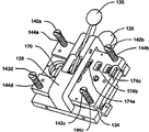
Fig. 5 is a skeleton view according to another illustrative portable cytometer of the present invention.The basic operation of Fig. 5 portable cytometer is similar to above just Fig. 1-4 the operation described.The portable cytometer of Fig. 5 totally is denoted as 120, and comprises pedestal 122, first parts 124, second parts 126, the clamp frame 128 that has clamp lever 130, air buffer module 132, the valve module subassembly 134 that has the miniature valve of polymkeric substance, air accumulation module 136 and optical elements sets component 140.
In described illustrative embodiment, second parts 126 are fixed on the pedestal 122.Several shoulder formula screws 142a, 142b, 142c and 142d (142d is not shown in Fig. 5) pass the hole of first parts 124, and are fixed on second parts 126. Spring 144a, 144b, 144c and 144d (144d is not shown in Fig. 5) are arranged on first parts 124 and take on accordingly between the head of formula screw 142a, 142b, 142c and 142d.Spring 144a, 144b, 144c and 144d provide the bias force of deflection second parts 126 for first parts 124.
As shown in the figure, clamp frame 128 is fixed on second parts 126.Clamp lever 130 interacts with the clamp frame clamp frame, so that provide outside bias force away from second parts 126 to first parts.First party move up that clamp lever 130, the first parts 124 just overcome inside bias force that spring 144a, 144b, 144c and 144d produce and with second isolation of components.Move up clamp lever 130, the first parts 124 just by the inside bias force promotion of spring 144a, 144b, 144c and 144d generation in opposite second party, shift to second parts 126.
In operating process, clamp lever 130 can move up in first party, makes first parts 124 leave second parts 126, reserves a space between them.Then, removable media member such as removable fluidic cartridge 150, can slip into described space.As shown in the figure, detachable box 150 can have front, the back side and extend in one or more sides between the front and back.Then as shown in Figure 5, can make first parts 124 shift to second parts 136, so that fixing and/or engagement removable media member 150 in the second party clamp lever 130 that moves up.Fig. 6 is the side perspective view of the described illustrative portable hemacytometer of Fig. 5.
In an illustrative embodiment, it is described to be similar to above just Fig. 1-4, and removable media member 130 fronts and/or the back side have one or more fluid port.It is contemplated that one or more fluid port are suitable for accepting gas or liquid.Second parts 126 of described illustrative embodiment comprise the corresponding liquid port, aim at one or more fluid port of removable media member 150.A fluid port like this is denoted as 160 at Fig. 6.Fluid port sealing gasket (seeing following Figure 12) can be fixed on second parts 126, so that help to provide better seal.
Then, the liquid control module can liquid be coupled to the fluid port of second parts 126.In described illustrative embodiment, the liquid control module comprises air accumulation module 136, has the valve module subassembly 134 and the air buffer module 132 of the miniature valve of polymkeric substance.Air accumulation module 136 comprises internal container, is used to accumulate the pressure of air.Port (not shown) from the internal container of air cushioning jar 136 to air pressure source can be set.The air pressure of gathering can offer valve module subassembly 134.The valve module subassembly can comprise one or more miniature valves, is 1100.1174101 the miniature valve of the disclosed polymkeric substance of U.S. Patent application such as being entitled as " static driven valve ", sequence number, and described U.S. Patent application is attached, and this is for referencial use.In described illustrative embodiment, as shown in above just Fig. 1-4 and description, valve module subassembly 134 can provide three independent pressure channels, comprises blood channel, cytolysate passage and covering liquid passage.The valve module subassembly 134 controller control in the pedestal 122 of feeling better most is so that provide three independent controlled pressure for air buffer module 132.Air buffer module 132 cushions described controlled pressure, and sends air pressurized by the fluid port of passing second parts 126 to the fluid port of removable media member 150.
In some cases, removable media member 150 can comprise one or more electric and/or optical devices.For example, in described illustrative embodiment, removable media member 150 can comprise three flow sensors, and each flow sensor is measured the flow rate by the fluid under pressure of three independent pressure channels of removable media member 150.Be similar to above-mentionedly, described flow sensor is heating power wind gage type flow sensor preferably, can be better from miniature electric bridge or little brick type flow sensor that Honeywell international (company) buys.Miniature bridge-type flow sensor for example in U.S. Patent No. 4,478,076, U.S. Patent No. 4,478,077, U.S. Patent No. 4,501,144, U.S. Patent No. 4,651, and 564, U.S. Patent No. 4,683,159 and U.S. Patent No. 5,050,429 in be described.These patents are all attached, and this is for referencial use.The output signal of each flow sensor all offers controller or the processor in the pedestal 122, preferably by electric, optics between the removable media member and second parts 126 and/or wireless coupling.
Fig. 7 is another skeleton view of the illustrative portable cytometer of Fig. 5, further illustrates other details.Fig. 7 illustrates the hole 170 by first parts 124 and second parts 126.Hole 170 make one or more light sources of optical package module 140 and one or more photodetector can be directly near the liquid stream window of detachable box (not shown in Fig. 7).
Fig. 7 also illustrates the one or more springs that are fixed on first parts 124 and loads probe.Described one or more spring loads probe and preferably is arranged to one or more when described detachable box is in desired location between first parts 124 and second parts 126 and on the described detachable box and electrically contacts pad alignment.In described illustrative embodiment, three springs are set load probe array 174a, 174b and 174c, each array is installed with a little printed circuit board (PCB), and is fixed in first parts, the 124 corresponding holes.The opposite side that spring loads probe can be led in hole in first parts 124, in certain embodiments, it can provide one easily the position realize that controller in the pedestal 122 and each spring load the electrical connection between the probe.
(perhaps as another program) in addition it is contemplated that one or more optical transmitting sets and/or fluorescence detector are fixed on first and/or second parts.Preferably described one or more optical transmitting sets and/or fluorescence detector are arranged to aim at one or more fluorescence detectors and/or optical transmitting set on the detachable box when detachable box is in desired position between first parts 124 and second parts 126.In case of necessity, can between detachable box and first parts and/or second parts 126, optical link be set.
Fig. 8 is the skeleton view of first parts 124 of the illustrative portable cytometer of Fig. 5.The spring that Fig. 8 illustrates Fig. 7 loads an opposite side of three arrays of probe 174a, 174b and 174c.Just as can be seen, each spring loads probe and is all being left first parts 124 and towards the outside direction upper offset of detachable box (not shown in Fig. 8) by spring.Described spring loads probe and preferably is arranged to when detachable box is between first parts 124 and second parts 126 on the desired position and one or morely on the detachable box electrically contacts pad alignment.When first parts 124 and second parts 126 are movable relative to each other so that fixing and/or when meshing described detachable box, spring load probe preferably with described detachable box on one or morely electrically contact pad and electrically contact.
When first parts 124 separate with second parts 126, electrically contact pad and separate in order to help spring to load one or more on probe and the described detachable box, outwards can between first parts 124 and detachable box, be provided with or separate bias unit 178.Look at Figure 11 earlier, outwards bias unit 178 can comprise chock 180 and spring 182.Spring 182 can be positioned in the depression 184 of first parts 124, and simultaneously spring 182 applies biasing on the outward direction to chock 180.
Later take another look at Fig. 8, when first parts 124 and second parts 126 are movable relative to each other,, can overcome described outside biasing 178 so that when fixing and/or engagement detachable box.Yet, when first parts 124 and second parts 126 separated from one another, so that when discharging described detachable box, outwards biasing 178 can make one or more springs load probe 174a, 174b and 174c to separate with one or more electric contacts on the described detachable box, this is easier to from taking-up between first parts 124 and second parts 126 detachable box, and can help prevent described spring loading probe to be damaged in the taking-up process.
First parts 124 can also have the one or more L shaped wedge that forms the line of rabbet joint, so that admit described detachable box.In the illustrative embodiment of Fig. 8, L shaped wedge 190 and following L shaped wedge 192 are set.For example, L shaped wedge 190 and 192 can comprise separately since first parts 124 stretch to first support 194 of second parts and from the far-end of first support 194 at second support 196 that extends perpendicular to the direction of first support 194, so that form passage or admit the line of rabbet joint 198.Then, the passage or the admittance line of rabbet joint 198 can be admitted a face of removable media member.In described illustrative embodiment, go up L shaped wedge 190 and be included in upwardly extending second support 196 downwards, and L shaped wedge 192 is included in upwardly extending upward second support down.In addition, go up L shaped wedge 190 and separate, admit the relative side (for example upper side and downside) of described detachable box that two passages that separate each other 196 are provided so that be with following L shaped wedge 192.That is to say, the passage of L shaped wedge 190 or the passage or the line of rabbet joint of the line of rabbet joint and following L shaped wedge 192 are set like this, make that described detachable box slips into two passages when detachable box being inserted between first parts 124 and second parts 126.In described illustrative embodiment, two L shaped wedges all are fixed on first parts 124.
In use, can make first parts 124 and second parts 126 separated from one another, and described detachable box can slip into the passages that are provided with by L shaped wedge 190 and 192 or admit slit 198, be positioned till pin 200 withstands until detachable box.L shaped wedge 190 and 192 preferably are set like this, make that detachable box is aimed at the desired position at least haply with respect to first parts 124 and/or second parts 126 when detachable box is admitted by L shaped wedge 190 and 192.First parts 124 and second parts 126 can be movable relative to each other then, so that described detachable box is meshed and/or is fixed between them.
In order to take out described detachable box, first parts 124 and second parts 126 can be separated from one another.Because the upper and lower edge of described detachable box is positioned in the passage or the line of rabbet joint 198 of L shaped wedge 190 and 192, so when first parts 124 and second parts 126 were separated from one another, described detachable box was held by second support of L shaped wedge 190 and 192 and is broken away from second parts 126.
For removable media member is alignd preferably with first and/or second parts, second parts can comprise one or more register pins 200 (seeing Figure 12) that extend to first parts.Then, removable media member 150 can comprise one or more receiving openings, is used to admit described one or more register pin 200a-200c.When removable media member 150 was fixed between first parts 124 and second parts 126, register pin 200a-200c and receiving opening can improve the location between removable media member 150 and first parts 124 and/or second parts 126.
L shaped wedge 190 and 192 preferably can be used for a removable media member 150 pullings away from second parts 126, thereby one or more receiving openings of removable media member 150 are separated with the one or more register pin 200a-200c that stretch out from second parts 126.Under described one or more receiving openings and situation that register pin 200a-200c separates, can be more easily removable media member 150 from taking out between first parts 124 and second parts 126.
Fig. 9 is the skeleton view of the hyposphene 192 of Fig. 8.Described illustrative hyposphene 192 comprises the first support 194a and the second support 196a, and wherein the second support 196a extends in vertical direction since the far-end of the first support 194a, forms passage or admits line of rabbet joint 198a.As shown in the figure, support rack 202a can extend from first support 194, is used for hyposphene 192 is supported in first parts 124.
Figure 10 is the skeleton view of wedge 190 on Fig. 8.The illustrative wedge 190 of going up comprises the first support 194b and the second support 196b, and wherein the second support 196b extends in vertical direction since the first support 194b far-end, forms passage or admits line of rabbet joint 190b.As shown in the figure, support rack 202b can extend from the first support 194b, is used for last wedge 190 is installed in first parts 124.
Figure 12 is second printed circuit board (PCB) of illustrative portable cytometer of Fig. 5 or the skeleton view of parts 126.Second parts 126 can be by being screwed into threaded hole 210a and 210b screw retention on pedestal 122.As what describe in detail above, second parts 126 can also comprise hole 170, and it makes one or more light sources of optical package module 140 and liquid that one or more photodetector can directly lead to detachable box stream window.
In described illustrative embodiment, second parts 126 comprise the tabular first type surface with the pocket portion that is used to admit detachable box.For location preferably is provided between detachable box and first parts 124 and/or second parts 126, second parts can comprise one or more register pin 200a-200c that stretch to first parts.Then, detachable box 150 can comprise one or more receiving openings, is used to admit one or more register pin 200a-200c.When detachable box was fixed between first parts 124 and second parts 126, register pin 200a-200c and receiving opening can improve the location between detachable box and first parts 124 and/or second parts 126.
Can comprise additional depression 212 and 214, so that admit the second support 196a and the 196b (seeing Fig. 8-10) that goes up L shaped wedge 190 and following L shaped wedge 192 respectively.By being provided for L shaped wedge 190 and second support 196a of following L shaped wedge 192 and the impression of 196b, detachable box can directly contact the surface of second parts 126.
In some cases, the manufacturing of detachable box may cause burr, burr or other defective, particularly centers on the neighboring of detachable box.In one example, fluidic cartridge can be by which floor or several sheet lamination together, cuts each fluidic cartridge from stepped construction then and makes.On line of cut, burr, burr and/or other defective may appear.Pack into for the flush ground that helps the detachable box and second parts 126, groove 216 or other relief structure can be set, on the admittance surface of second parts 126 so that hold the one or more defectives in the detachable box.In the illustrative embodiment of Figure 12, extend in the groove path that groove 216 can stretch along the periphery around detachable box.Yet, it is contemplated that, groove or other relief structure are set on any position that the defective that can expect in detachable box may occur.It is also conceivable that in case of necessity groove or other relief structure can be set on the admittance surface of first parts 124.
In an illustrative embodiment, detachable box has one or more fluid port, is similar to above described with regard to Fig. 1-4.It is contemplated that one or more fluid port can be suitable for accepting gas or liquid according to purposes.Second parts 126 of described illustrative embodiment comprise corresponding liquid port 220a-220c, aim at one or more fluid port of detachable box.Fluid port sealing gasket 222 can be fixed on second parts 126, so that help to provide better seal in case of necessity.
Although described most preferred embodiment of the present invention, the professional and technical personnel is understood that within the scope of accompanying Claim book, teaching of finding can also be applied to other embodiment here.
Claims (38)
1. equipment that is used to admit removable media member, described removable media member has front, the back side and one or more side that extends between the described front and the described back side, and described equipment comprises:
First parts;
Second parts;
Described first parts and described second parts are suitable for along axle separated from one another so that be provided for admitting the space of described removable media member and edge axle to be movable relative to each other so that fix described removable media member; With
Described first parts have first chock that has first support and second support, described first support of described first chock extends to described second parts from described first parts, described second support of described first chock is extending laterally with respect to described first support, described first support and described second support are formed for admitting the passage of described removable media member, make described first support mesh one or more sides of described removable media member, and described second support mesh the described front of described removable media member or at least a portion at the described back side.
2. equipment as claimed in claim 1, described first support wherein is set like this, make that described removable media member is aimed at the desired position at least haply with respect to described first parts and/or described second parts when described removable media member during by described first parts and the admittance of described second parts.
3. equipment as claimed in claim 2, wherein said second parts comprise one or more register pins, and described removable media member comprises the one or more receiving openings that are used to admit described one or more register pins.
4. equipment as claimed in claim 3, described first support wherein is set like this, make that the described one or more receiving openings in the described removable media member are aimed at described one or more register pins of described second parts at least haply when described removable media member during by described first parts and the admittance of described second parts.
5. equipment as claimed in claim 4, described second support of wherein said first chock is suitable for meshing described removable media member, and when described first parts and described second parts are separated from one another, described detachable media is extracted from described one or more register pins of described second parts.
6. equipment as claimed in claim 5, wherein said first parts also comprise second chock that separates with described first chock, described second chock comprises first support and second support, described first support of wherein said second chock stretches to described second parts from described first parts, and described second support of described second chock is with respect to described first chock of transversely stretching to of described first support, described first support of described second chock and described second support are formed for admitting the passage of described removable media member, make described first support of described second chock be positioned at the one or more sides position adjacent with described removable media member, and described second support of described second chock mesh the front of described removable media member or at least a portion of one in the back side.
7. equipment as claimed in claim 6, described first support of wherein said first chock is positioned at a position adjacent in described one or more sides with described removable media member, and described first support of described second chock is positioned at a relative side position adjacent in described each side with described removable media member.
8. equipment as claimed in claim 7, the front that described second support of wherein said first chock and described second support of described second chock all mesh described removable media member.
9. equipment as claimed in claim 8, wherein said removable media member is a fluidic cartridge.
10. equipment as claimed in claim 3, in wherein said one or more register pin at least one is stop pin, when described removable media member was fully inserted between described first parts and described second parts, described stop pin was suitable for withstanding at least one side in described each side of described removable media member.
11. equipment as claimed in claim 1, wherein said second parts are fixed, and described first parts can move to described second parts.
12. equipment as claimed in claim 1, wherein said removable media member has one or more electric contacts, and
Described first parts have the one or more springs that outwards stretch to described second parts and load probe, described one or more spring loads probe and is arranged to when described removable media member is in desired position between described first parts and described second parts, and some electric contacts of selecting at least that described one or more springs load in described one or more electric contacts of probes and described removable media member are aimed at.
13. equipment as claimed in claim 12, in wherein said first parts and described second parts at least one comprises described one or more register pin, and described removable media member comprises one or more receiving openings, is used for admitting when described removable media member is on the desired position between described first parts and described second parts described one or more register pin.
14. equipment as claimed in claim 12, wherein said first parts also comprise outside bias unit, are used for providing bias force to described removable media member, and described bias force points to the direction of leaving described first parts.
15. equipment as claimed in claim 14 wherein is movable relative to each other when described first parts and described second parts, so that during fixing described removable media member, overcomes the bias force of described outside bias unit.
16. equipment as claimed in claim 15, wherein when described first parts and described second parts are separated from one another, the bias force of described outside bias unit promotes described removable media member and leaves described one or more spring and load probe.
17. equipment as claimed in claim 14, wherein said outside bias unit comprises spring.
18. equipment as claimed in claim 17, wherein said outside bias unit comprises the chock that is biased to the external position of leaving described first parts by described spring.
19. equipment as claimed in claim 12, wherein said removable media member are fluidic cartridge.
20. equipment as claimed in claim 19, wherein said removable media member comprises:
One or more flow channels; With
Selected some flow channel fluid connections in the one or more flow sensors, they and described one or more flow channel, described one or more flow sensors are electrically connected to some selected in described one or more electric contact electric contacts.
21. equipment as claimed in claim 19, wherein said removable media member comprises one or more pumps, and wherein said one or more pumps are electrically connected to some selected in described one or more electric contact electric contacts.
22. equipment as claimed in claim 1, wherein said removable media member has one or more fluid port, and
Described second parts have one or more fluid port, and described one or more fluid port are arranged to be aimed at at least some selected fluid port of described removable media member fixedly the time by described first parts and described second parts when described removable media member.
23. equipment as claimed in claim 22, in wherein said first parts and described second parts one or both comprise one or more register pins, and described removable media member comprises the one or more holes that are used to admit described one or more register pins.
24. equipment as claimed in claim 22, wherein be movable relative to each other so that during fixing described removable media member when described first parts and described second parts, between described one or more fluid port of described one or more fluid port of described second parts and described removable media member, form seal.
25. equipment as claimed in claim 22 wherein also comprises when described first parts and described second parts are separated from one another the device that described removable media member is separated with described one or more fluid port of described second parts.
26. equipment as claimed in claim 22, described one or more fluid port of wherein said second parts and described one or more fluid port of described removable media member are suitable for carrying gas.
27. equipment as claimed in claim 22, described one or more fluid port of wherein said second parts and described one or more fluid port of described removable media member are suitable for carrying liquid.
28. equipment as claimed in claim 22, wherein said removable media member is a fluidic cartridge.
29. equipment as claimed in claim 1, wherein said removable media member have one or more electric contacts and one or more fluid port, and
In described first parts and/or described second parts at least one has one or more springs and loads probe, described one or more spring loads probe and is arranged to when described removable media member during by described first parts and the admittance of described second parts, aim at some the selected at least electric contacts in one or more electric contacts on the described removable media member and
In described first parts and/or described second parts at least one has one or more fluid port, described one or more fluid port is arranged to when described removable media member is admitted by described first parts and described second parts, aims at some selected in described each fluid port of described removable media member fluid port.
30. equipment as claimed in claim 29, at least one comprises outside bias unit in wherein said first parts and/or described second parts, and being used for provides the bias force that leaves described one or more spring loading probes to described removable media member.
31. equipment as claimed in claim 29, wherein working as described first parts and described second parts is movable relative to each other, so that during fixing described removable media member, in described first parts and/or described second parts, form seal between described one or more fluid port of described one or more fluid port of at least one and described removable media member.
32. equipment as claimed in claim 1, wherein said first parts have groove therein, when described removable media member was in the desired position with respect to described first parts and described second parts, described groove extended along the groove path corresponding to the periphery in described removable media member front.
33. equipment as claimed in claim 32, wherein said removable media member comprise around some kinds of defectives of the periphery in described removable media member front, and described groove provides the impression space to described some kinds of defectives.
34. equipment as claimed in claim 32, wherein said removable media member is a fluidic cartridge.
35. a method of admitting removable media member, described removable media member have front, the back side and extend in described front and and the described back side between one or more sides, said method comprising the steps of:
First parts are provided;
Second parts are provided;
Make described first parts and described second parts separated from one another, so that the space is provided between them along axle;
Described removable media member is inserted described space between described first parts and described second parts;
Described first parts and described second parts are moved relative to one another, so that fixing described removable media member along axle;
Make described first parts and described second parts separated from one another along axle; And
When described first parts and described second parts are separated from one another, described removable media member is moved with described first parts.
36. method as claimed in claim 35, wherein said second parts comprise one or more register pins, and described removable media member comprises the one or more receiving openings that are used to admit described one or more register pins, when described first parts and described second parts are movable relative to each other, so that during fixing described removable media member, described one or more receiving openings of described removable media member are admitted described one or more register pin.
37. method as claimed in claim 36, wherein when described first parts and described second parts removable media member separated from one another and described were mobile with described first parts, described one or more register pins were extracted out by the described one or more holes from described removable media member.
38. method as claimed in claim 36, wherein said removable media member is a fluidic cartridge.
Applications Claiming Priority (5)
| Application Number | Priority Date | Filing Date | Title |
|---|---|---|---|
| US40487602P | 2002-08-21 | 2002-08-21 | |
| US60/404,876 | 2002-08-21 | ||
| US10/612,664 | 2003-07-02 | ||
| US10/612,664 US7000330B2 (en) | 2002-08-21 | 2003-07-02 | Method and apparatus for receiving a removable media member |
| PCT/US2003/025779 WO2004019013A2 (en) | 2002-08-21 | 2003-08-15 | Method and apparatus for receiving a removable media member |
Publications (2)
| Publication Number | Publication Date |
|---|---|
| CN1688875A CN1688875A (en) | 2005-10-26 |
| CN1688875B true CN1688875B (en) | 2010-10-27 |
Family
ID=31949875
Family Applications (1)
| Application Number | Title | Priority Date | Filing Date |
|---|---|---|---|
| CN03824344XA Expired - Fee Related CN1688875B (en) | 2002-08-21 | 2003-08-15 | Method and apparatus for receiving a removable media member |
Country Status (6)
| Country | Link |
|---|---|
| US (1) | US7000330B2 (en) |
| EP (1) | EP1556680B1 (en) |
| JP (1) | JP4171744B2 (en) |
| CN (1) | CN1688875B (en) |
| AU (1) | AU2003258281A1 (en) |
| WO (1) | WO2004019013A2 (en) |
Families Citing this family (25)
| Publication number | Priority date | Publication date | Assignee | Title |
|---|---|---|---|---|
| US7641856B2 (en) * | 2004-05-14 | 2010-01-05 | Honeywell International Inc. | Portable sample analyzer with removable cartridge |
| US8518328B2 (en) * | 2005-12-27 | 2013-08-27 | Honeywell International Inc. | Fluid sensing and control in a fluidic analyzer |
| CA2563002C (en) | 2004-04-07 | 2011-07-12 | Wardlaw Partners Lp | Disposable chamber for analyzing biologic fluids |
| US8323564B2 (en) * | 2004-05-14 | 2012-12-04 | Honeywell International Inc. | Portable sample analyzer system |
| US8097225B2 (en) * | 2004-07-28 | 2012-01-17 | Honeywell International Inc. | Microfluidic cartridge with reservoirs for increased shelf life of installed reagents |
| US7333197B2 (en) * | 2004-11-17 | 2008-02-19 | Honeywell International Inc. | Raman detection based flow cytometer |
| US20070045128A1 (en) * | 2005-08-19 | 2007-03-01 | Honeywell International Inc. | Chlorine dioxide sensor |
| US7731901B2 (en) | 2005-10-19 | 2010-06-08 | Abbott Laboratories | Apparatus and method for performing counts within a biologic fluid sample |
| EP1963866B1 (en) | 2005-12-22 | 2018-05-16 | Honeywell International Inc. | Hematological analyzer system with removable cartridge |
| US8182767B2 (en) * | 2005-12-27 | 2012-05-22 | Honeywell International Inc. | Needle-septum interface for a fluidic analyzer |
| US7485153B2 (en) * | 2005-12-27 | 2009-02-03 | Honeywell International Inc. | Fluid free interface for a fluidic analyzer |
| US8348769B2 (en) * | 2006-03-22 | 2013-01-08 | Wms Gaming Inc. | Wagering game machine with a toolless hard drive mount |
| WO2007115378A1 (en) * | 2006-04-11 | 2007-10-18 | Minifab (Australia) Pty Ltd | Microfluidic package housing |
| EP2086684B1 (en) | 2006-10-25 | 2012-02-08 | Fraunhofer-Gesellschaft zur Förderung der angewandten Forschung e.V. | Chip holder, fluidic system and chip holder system |
| US20090038171A1 (en) * | 2007-08-08 | 2009-02-12 | International Business Machines Corporation | Alignment tool for assembly of microprocessor board to server chassis |
| US9034277B2 (en) | 2008-10-24 | 2015-05-19 | Honeywell International Inc. | Surface preparation for a microfluidic channel |
| US9579651B2 (en) * | 2009-12-18 | 2017-02-28 | Abbott Point Of Care, Inc. | Biologic fluid analysis cartridge |
| CN103282123B (en) | 2010-12-30 | 2015-05-06 | 艾博特健康公司 | Biologic fluid analysis cartridge with sample handling portion and analysis chamber portion |
| CN202548048U (en) * | 2011-01-10 | 2012-11-21 | 伊鲁米那股份有限公司 | Flow cell and jet device for analyzing samples |
| US8951781B2 (en) | 2011-01-10 | 2015-02-10 | Illumina, Inc. | Systems, methods, and apparatuses to image a sample for biological or chemical analysis |
| EP2748618A1 (en) | 2011-08-24 | 2014-07-02 | Abbott Point of Care Inc. | Biologic fluid sample analysis cartridge |
| US9207166B2 (en) * | 2013-01-31 | 2015-12-08 | Honeywell International Inc. | Micro-molded cytometer cartridge with integrated optics |
| CN113331832A (en) * | 2014-03-12 | 2021-09-03 | 赛拉诺斯知识产权有限责任公司 | Device and method for bodily fluid sample collection |
| US10471425B2 (en) | 2017-02-16 | 2019-11-12 | International Business Machines Corporation | Automated machine for sorting of biological fluids |
| CN111774115B (en) * | 2020-05-29 | 2021-09-07 | 东南大学 | Clamp device for fixing micro-fluidic chip with electrodes |
Citations (1)
| Publication number | Priority date | Publication date | Assignee | Title |
|---|---|---|---|---|
| US3877075A (en) * | 1972-06-17 | 1975-04-08 | Sony Corp | Magnetic tape apparatus with improved cassette insertion and removal |
Family Cites Families (103)
| Publication number | Priority date | Publication date | Assignee | Title |
|---|---|---|---|---|
| US2403692A (en) * | 1944-12-29 | 1946-07-09 | George C Tibbetts | Piezoelectric device |
| US2975307A (en) * | 1958-01-02 | 1961-03-14 | Ibm | Capacitive prime mover |
| US3304446A (en) * | 1963-12-26 | 1967-02-14 | Union Oil Co | Electrostrictive fluid transducer |
| US3414010A (en) | 1965-11-01 | 1968-12-03 | Honeywell Inc | Control apparatus |
| US3381623A (en) * | 1966-04-26 | 1968-05-07 | Harold F Elliott | Electromagnetic reciprocating fluid pump |
| CH1494868A4 (en) * | 1968-10-08 | 1971-03-15 | Proctor Ets | |
| US3726296A (en) * | 1971-08-09 | 1973-04-10 | Process Systems | Fluidic control system and method for calibrating same |
| JPS4829420A (en) * | 1971-08-20 | 1973-04-19 | ||
| US3803424A (en) * | 1972-05-08 | 1974-04-09 | Physics Int Co | Piezoelectric pump system |
| US3827457A (en) * | 1973-06-22 | 1974-08-06 | Westinghouse Air Brake Co | Fluid pressure system for converting digital signals to analog signals |
| US3976862A (en) * | 1975-03-18 | 1976-08-24 | Block Engineering, Inc. | Flow stream processor |
| GB1530662A (en) * | 1976-03-01 | 1978-11-01 | Mullard Ltd | Peristaltic pump |
| US4244109A (en) * | 1976-10-19 | 1981-01-13 | Pertec Computer Corporation | Apparatus for mounting and aligning printed circuit board |
| US4197737A (en) * | 1977-05-10 | 1980-04-15 | Applied Devices Corporation | Multiple sensing device and sensing devices therefor |
| US4140936A (en) * | 1977-09-01 | 1979-02-20 | The United States Of America As Represented By The Secretary Of The Navy | Square and rectangular electroacoustic bender bar transducer |
| IL59942A (en) * | 1980-04-28 | 1986-08-31 | D P Lab Ltd | Method and device for fluid transfer |
| DE3108693A1 (en) | 1981-03-07 | 1982-09-23 | Walter Ing.(grad.) 7758 Meersburg Holzer | ELECTROMAGNETIC VALVE, ESPECIALLY FOR HOME APPLIANCES |
| US4498112A (en) * | 1982-03-22 | 1985-02-05 | Data Electronics, Inc. | Tape cartridge receptacle |
| US4453169A (en) * | 1982-04-07 | 1984-06-05 | Exxon Research And Engineering Co. | Ink jet apparatus and method |
| US4651564A (en) * | 1982-09-30 | 1987-03-24 | Honeywell Inc. | Semiconductor device |
| US4683159A (en) * | 1982-09-30 | 1987-07-28 | Honeywell Inc. | Semiconductor device structure and processing |
| US4501144A (en) * | 1982-09-30 | 1985-02-26 | Honeywell Inc. | Flow sensor |
| US4478077A (en) * | 1982-09-30 | 1984-10-23 | Honeywell Inc. | Flow sensor |
| US4478076A (en) * | 1982-09-30 | 1984-10-23 | Honeywell Inc. | Flow sensor |
| US4539614A (en) * | 1983-05-18 | 1985-09-03 | Drivetec, Inc. | Flexible magnetic disk clamping an injector mechanism |
| DE3320441A1 (en) * | 1983-06-06 | 1984-12-06 | Siemens AG, 1000 Berlin und 8000 München | WRITING DEVICE WORKING WITH LIQUID DROPLETS WITH ROD-SHAPED PIEZOELECTRIC TRANSFORMERS CONNECTED ON BOTH ENDS WITH A NOZZLE PLATE |
| DE3515499C2 (en) * | 1984-05-01 | 1994-08-04 | Smc Kk | Electropneumatic converter |
| US4673995A (en) * | 1984-07-06 | 1987-06-16 | Kennedy Company | Cartridge tape drive with friction roller to open cartridge door |
| US4576050A (en) * | 1984-08-29 | 1986-03-18 | General Motors Corporation | Thermal diffusion fluid flow sensor |
| US4654546A (en) * | 1984-11-20 | 1987-03-31 | Kari Kirjavainen | Electromechanical film and procedure for manufacturing same |
| JPS61123868A (en) * | 1984-11-21 | 1986-06-11 | キヤノン株式会社 | Positioning securing method for panel substrate |
| JPS61173319A (en) * | 1985-01-26 | 1986-08-05 | Shoketsu Kinzoku Kogyo Co Ltd | Regulator for fluid |
| US4756508A (en) * | 1985-02-21 | 1988-07-12 | Ford Motor Company | Silicon valve |
| US4745279A (en) * | 1986-01-02 | 1988-05-17 | American Hospital Supply Corporation | Hematocrit measuring apparatus |
| JPH0729414B2 (en) * | 1987-01-22 | 1995-04-05 | 株式会社テック | Valve element and manufacturing method thereof |
| US4874949A (en) * | 1987-09-14 | 1989-10-17 | Vanderbilt University | Method of measuring lung vascular function and transcapillary transport by the use of nonradioactive markers |
| JPH01174278A (en) * | 1987-12-28 | 1989-07-10 | Misuzu Erii:Kk | Inverter |
| US4911616A (en) * | 1988-01-19 | 1990-03-27 | Laumann Jr Carl W | Micro miniature implantable pump |
| US4938742A (en) * | 1988-02-04 | 1990-07-03 | Smits Johannes G | Piezoelectric micropump with microvalves |
| US5065978A (en) * | 1988-04-27 | 1991-11-19 | Dragerwerk Aktiengesellschaft | Valve arrangement of microstructured components |
| JP2709318B2 (en) * | 1988-08-31 | 1998-02-04 | セイコープレシジョン株式会社 | Liquid crystal panel and conversion device using liquid crystal panel |
| CH679555A5 (en) * | 1989-04-11 | 1992-03-13 | Westonbridge Int Ltd | |
| DE69011631T2 (en) * | 1989-06-14 | 1995-03-23 | Westonbridge Int Ltd | MICRO PUMP. |
| US5069419A (en) | 1989-06-23 | 1991-12-03 | Ic Sensors Inc. | Semiconductor microactuator |
| DE3925749C1 (en) * | 1989-08-03 | 1990-10-31 | Fraunhofer-Gesellschaft Zur Foerderung Der Angewandten Forschung Ev, 8000 Muenchen, De | |
| DE3926066A1 (en) * | 1989-08-07 | 1991-02-14 | Ibm Deutschland | MICROMECHANICAL COMPRESSOR CASCADE AND METHOD FOR INCREASING PRINTER AT EXTREMELY LOW WORKING PRESSURE |
| CH681168A5 (en) * | 1989-11-10 | 1993-01-29 | Westonbridge Int Ltd | Micro-pump for medicinal dosing |
| US5171132A (en) | 1989-12-27 | 1992-12-15 | Seiko Epson Corporation | Two-valve thin plate micropump |
| US5096388A (en) * | 1990-03-22 | 1992-03-17 | The Charles Stark Draper Laboratory, Inc. | Microfabricated pump |
| DE69104585T2 (en) * | 1990-10-30 | 1995-05-18 | Hewlett Packard Co | Micropump. |
| DE69129260T2 (en) * | 1990-11-03 | 1998-11-19 | Horiba Ltd | Device for measuring the particle size distribution |
| US5206557A (en) * | 1990-11-27 | 1993-04-27 | Mcnc | Microelectromechanical transducer and fabrication method |
| DE4119955C2 (en) * | 1991-06-18 | 2000-05-31 | Danfoss As | Miniature actuator |
| US5176358A (en) * | 1991-08-08 | 1993-01-05 | Honeywell Inc. | Microstructure gas valve control |
| US5192197A (en) * | 1991-11-27 | 1993-03-09 | Rockwell International Corporation | Piezoelectric pump |
| JPH0678566A (en) * | 1992-08-25 | 1994-03-18 | Kanagawa Kagaku Gijutsu Akad | Electrostatic actuator |
| US5441597A (en) * | 1992-12-01 | 1995-08-15 | Honeywell Inc. | Microstructure gas valve control forming method |
| JPH06338116A (en) * | 1993-03-31 | 1994-12-06 | Canon Inc | Optical information recording/reproducing device |
| US5642015A (en) * | 1993-07-14 | 1997-06-24 | The University Of British Columbia | Elastomeric micro electro mechanical systems |
| US5368704A (en) * | 1993-08-06 | 1994-11-29 | Teknekron Corporation | Micro-electrochemical valves and method |
| JPH07184377A (en) * | 1993-10-21 | 1995-07-21 | Mitsubishi Chem Corp | Electrostatic actuator |
| US5499909A (en) * | 1993-11-17 | 1996-03-19 | Aisin Seiki Kabushiki Kaisha Of Kariya | Pneumatically driven micro-pump |
| CA2179063C (en) * | 1993-12-28 | 2005-02-15 | Harald Van Lintel | Micropump |
| CH689836A5 (en) * | 1994-01-14 | 1999-12-15 | Westonbridge Int Ltd | Micropump. |
| DE4402119C2 (en) * | 1994-01-25 | 1998-07-23 | Karlsruhe Forschzent | Process for the production of micromembrane pumps |
| US5585069A (en) * | 1994-11-10 | 1996-12-17 | David Sarnoff Research Center, Inc. | Partitioned microelectronic and fluidic device array for clinical diagnostics and chemical synthesis |
| US5601080A (en) * | 1994-12-28 | 1997-02-11 | Coretech Medical Technologies Corporation | Spectrophotometric blood analysis |
| US5793485A (en) * | 1995-03-20 | 1998-08-11 | Sandia Corporation | Resonant-cavity apparatus for cytometry or particle analysis |
| US5788833A (en) * | 1995-03-27 | 1998-08-04 | California Institute Of Technology | Sensors for detecting analytes in fluids |
| US5571401A (en) * | 1995-03-27 | 1996-11-05 | California Institute Of Technology | Sensor arrays for detecting analytes in fluids |
| US5528045A (en) * | 1995-04-06 | 1996-06-18 | Becton Dickinson And Company | Particle analyzer with spatially split wavelength filter |
| US5932100A (en) * | 1995-06-16 | 1999-08-03 | University Of Washington | Microfabricated differential extraction device and method |
| US5922210A (en) * | 1995-06-16 | 1999-07-13 | University Of Washington | Tangential flow planar microfabricated fluid filter and method of using thereof |
| US5716852A (en) * | 1996-03-29 | 1998-02-10 | University Of Washington | Microfabricated diffusion-based chemical sensor |
| US5633724A (en) * | 1995-08-29 | 1997-05-27 | Hewlett-Packard Company | Evanescent scanning of biochemical array |
| US5726751A (en) * | 1995-09-27 | 1998-03-10 | University Of Washington | Silicon microchannel optical flow cytometer |
| JP3308441B2 (en) * | 1995-12-19 | 2002-07-29 | シスメックス株式会社 | Urine particle analyzer |
| US5863502A (en) * | 1996-01-24 | 1999-01-26 | Sarnoff Corporation | Parallel reaction cassette and associated devices |
| US5948684A (en) * | 1997-03-31 | 1999-09-07 | University Of Washington | Simultaneous analyte determination and reference balancing in reference T-sensor devices |
| US6014358A (en) * | 1996-04-04 | 2000-01-11 | Teac Corporation | Recording medium cartridge loading device |
| JP2000512541A (en) * | 1996-06-14 | 2000-09-26 | ユニバーシティ オブ ワシントン | Difference extraction device with improved absorption |
| US5764674A (en) * | 1996-06-28 | 1998-06-09 | Honeywell Inc. | Current confinement for a vertical cavity surface emitting laser |
| US5799030A (en) * | 1996-07-26 | 1998-08-25 | Honeywell Inc. | Semiconductor device with a laser and a photodetector in a common container |
| US5897097A (en) * | 1996-09-06 | 1999-04-27 | Xerox Corporation | Passively addressable fluid valves having S-shaped blocking films |
| US5683159A (en) * | 1997-01-03 | 1997-11-04 | Johnson; Greg P. | Hardware mounting rail |
| US5974867A (en) | 1997-06-13 | 1999-11-02 | University Of Washington | Method for determining concentration of a laminar sample stream |
| US6139800A (en) * | 1997-06-23 | 2000-10-31 | Luminex Corporation | Interlaced lasers for multiple fluorescence measurement |
| US6082185A (en) * | 1997-07-25 | 2000-07-04 | Research International, Inc. | Disposable fluidic circuit cards |
| US5880474A (en) * | 1997-08-29 | 1999-03-09 | Becton Dickinson And Company | Multi-illumination-source flow particle analyzer with inter-location emissions crosstalk cancelation |
| US6007775A (en) | 1997-09-26 | 1999-12-28 | University Of Washington | Multiple analyte diffusion based chemical sensor |
| US5836750A (en) | 1997-10-09 | 1998-11-17 | Honeywell Inc. | Electrostatically actuated mesopump having a plurality of elementary cells |
| US6106245A (en) * | 1997-10-09 | 2000-08-22 | Honeywell | Low cost, high pumping rate electrostatically actuated mesopump |
| US5901939A (en) * | 1997-10-09 | 1999-05-11 | Honeywell Inc. | Buckled actuator with enhanced restoring force |
| US5822170A (en) * | 1997-10-09 | 1998-10-13 | Honeywell Inc. | Hydrophobic coating for reducing humidity effect in electrostatic actuators |
| US6215221B1 (en) * | 1998-12-29 | 2001-04-10 | Honeywell International Inc. | Electrostatic/pneumatic actuators for active surfaces |
| US6184607B1 (en) * | 1998-12-29 | 2001-02-06 | Honeywell International Inc. | Driving strategy for non-parallel arrays of electrostatic actuators sharing a common electrode |
| US6249341B1 (en) * | 1999-01-25 | 2001-06-19 | Amnis Corporation | Imaging and analyzing parameters of small moving objects such as cells |
| US6097485A (en) * | 1999-03-08 | 2000-08-01 | Integrated Waveguides, Inc. | Microchip optical transport technology for use in a personal flow cytometer |
| US6179586B1 (en) * | 1999-09-15 | 2001-01-30 | Honeywell International Inc. | Dual diaphragm, single chamber mesopump |
| US6383005B2 (en) * | 1999-12-07 | 2002-05-07 | Urex Precision, Inc. | Integrated circuit socket with contact pad |
| US6597438B1 (en) * | 2000-08-02 | 2003-07-22 | Honeywell International Inc. | Portable flow cytometry |
| JP2001357654A (en) * | 2000-06-16 | 2001-12-26 | Sony Corp | Tape cassette and cassette holder |
| TW580207U (en) * | 2003-03-05 | 2004-03-11 | Hon Hai Prec Ind Co Ltd | Electrical connector assembly |
-
2003
- 2003-07-02 US US10/612,664 patent/US7000330B2/en not_active Expired - Lifetime
- 2003-08-15 EP EP03793098.9A patent/EP1556680B1/en not_active Expired - Lifetime
- 2003-08-15 WO PCT/US2003/025779 patent/WO2004019013A2/en active Application Filing
- 2003-08-15 CN CN03824344XA patent/CN1688875B/en not_active Expired - Fee Related
- 2003-08-15 JP JP2005501758A patent/JP4171744B2/en not_active Expired - Fee Related
- 2003-08-15 AU AU2003258281A patent/AU2003258281A1/en not_active Abandoned
Patent Citations (1)
| Publication number | Priority date | Publication date | Assignee | Title |
|---|---|---|---|---|
| US3877075A (en) * | 1972-06-17 | 1975-04-08 | Sony Corp | Magnetic tape apparatus with improved cassette insertion and removal |
Non-Patent Citations (1)
| Title |
|---|
| 同上. |
Also Published As
| Publication number | Publication date |
|---|---|
| EP1556680B1 (en) | 2020-04-01 |
| JP2006514742A (en) | 2006-05-11 |
| EP1556680A2 (en) | 2005-07-27 |
| WO2004019013A2 (en) | 2004-03-04 |
| US20040211077A1 (en) | 2004-10-28 |
| AU2003258281A1 (en) | 2004-03-11 |
| CN1688875A (en) | 2005-10-26 |
| JP4171744B2 (en) | 2008-10-29 |
| WO2004019013A3 (en) | 2004-06-03 |
| US7000330B2 (en) | 2006-02-21 |
Similar Documents
| Publication | Publication Date | Title |
|---|---|---|
| CN1688875B (en) | Method and apparatus for receiving a removable media member | |
| CN101223434B (en) | Cytometer analysis cartridge optical configuration | |
| JP2006514742A5 (en) | ||
| US7312870B2 (en) | Optical alignment detection system | |
| CN101208593B (en) | A flow control system of a card | |
| US7016022B2 (en) | Dual use detectors for flow cytometry | |
| US6549275B1 (en) | Optical detection system for flow cytometry | |
| US6382228B1 (en) | Fluid driving system for flow cytometry | |
| US7671987B2 (en) | Optical detection system for flow cytometry | |
| CN100573546C (en) | The method and apparatus that is used for document of identify and article | |
| US7215425B2 (en) | Optical alignment for flow cytometry | |
| CN105452831A (en) | Pressure sensor, measuring device, reaction carrier and measuring method | |
| CN104062699A (en) | Sealing Structure, Interference Filter, Optical Module, And Electronic Apparatus | |
| CA2316632A1 (en) | Signal interface module | |
| CN207379692U (en) | A kind of speaker leak tightness testing equipment | |
| CN101583495A (en) | Ink container and ink jetting device | |
| CN208537379U (en) | A kind of microlayer model detection device | |
| CN219996293U (en) | Chip test system of flow sensor | |
| US20230375587A1 (en) | Microfluidic flow control | |
| CN209077203U (en) | A kind of pressing machine examination needle mechanism | |
| CN114487455A (en) | In-vitro diagnostic instrument and control method thereof | |
| WO2019177645A1 (en) | Reagent container for an aldehyde analysis system and method of use | |
| CN108554834A (en) | A kind of equipment for detecting Classing filing appliance | |
| Microcytometer | The BioFlip Microcytometer | |
| CN101868698A (en) | Meter provided with means for detecting fraud or attempted fraud |
Legal Events
| Date | Code | Title | Description |
|---|---|---|---|
| C06 | Publication | ||
| PB01 | Publication | ||
| C10 | Entry into substantive examination | ||
| SE01 | Entry into force of request for substantive examination | ||
| C14 | Grant of patent or utility model | ||
| GR01 | Patent grant | ||
| CF01 | Termination of patent right due to non-payment of annual fee |
Granted publication date: 20101027 Termination date: 20210815 |
|
| CF01 | Termination of patent right due to non-payment of annual fee |