CN1643247A - Extracting power from a fluid flow - Google Patents
Extracting power from a fluid flow Download PDFInfo
- Publication number
- CN1643247A CN1643247A CNA038064251A CN03806425A CN1643247A CN 1643247 A CN1643247 A CN 1643247A CN A038064251 A CNA038064251 A CN A038064251A CN 03806425 A CN03806425 A CN 03806425A CN 1643247 A CN1643247 A CN 1643247A
- Authority
- CN
- China
- Prior art keywords
- fluid
- constriction
- driving
- flow
- equipment
- Prior art date
- Legal status (The legal status is an assumption and is not a legal conclusion. Google has not performed a legal analysis and makes no representation as to the accuracy of the status listed.)
- Pending
Links
Images


Classifications
-
- F—MECHANICAL ENGINEERING; LIGHTING; HEATING; WEAPONS; BLASTING
- F03—MACHINES OR ENGINES FOR LIQUIDS; WIND, SPRING, OR WEIGHT MOTORS; PRODUCING MECHANICAL POWER OR A REACTIVE PROPULSIVE THRUST, NOT OTHERWISE PROVIDED FOR
- F03B—MACHINES OR ENGINES FOR LIQUIDS
- F03B17/00—Other machines or engines
-
- Y—GENERAL TAGGING OF NEW TECHNOLOGICAL DEVELOPMENTS; GENERAL TAGGING OF CROSS-SECTIONAL TECHNOLOGIES SPANNING OVER SEVERAL SECTIONS OF THE IPC; TECHNICAL SUBJECTS COVERED BY FORMER USPC CROSS-REFERENCE ART COLLECTIONS [XRACs] AND DIGESTS
- Y02—TECHNOLOGIES OR APPLICATIONS FOR MITIGATION OR ADAPTATION AGAINST CLIMATE CHANGE
- Y02E—REDUCTION OF GREENHOUSE GAS [GHG] EMISSIONS, RELATED TO ENERGY GENERATION, TRANSMISSION OR DISTRIBUTION
- Y02E10/00—Energy generation through renewable energy sources
- Y02E10/20—Hydro energy
-
- Y—GENERAL TAGGING OF NEW TECHNOLOGICAL DEVELOPMENTS; GENERAL TAGGING OF CROSS-SECTIONAL TECHNOLOGIES SPANNING OVER SEVERAL SECTIONS OF THE IPC; TECHNICAL SUBJECTS COVERED BY FORMER USPC CROSS-REFERENCE ART COLLECTIONS [XRACs] AND DIGESTS
- Y02—TECHNOLOGIES OR APPLICATIONS FOR MITIGATION OR ADAPTATION AGAINST CLIMATE CHANGE
- Y02E—REDUCTION OF GREENHOUSE GAS [GHG] EMISSIONS, RELATED TO ENERGY GENERATION, TRANSMISSION OR DISTRIBUTION
- Y02E10/00—Energy generation through renewable energy sources
- Y02E10/30—Energy from the sea, e.g. using wave energy or salinity gradient
Abstract
An apparatus for extracting power from a fluid flow, the apparatus comprises a fluid driveable engine (300), a fluid directing arrangement (100) formed to define a channel in the flow of a primary fluid, the channel having a flow accelerating constriction shaped such that the primary fluid accelerates as it passes through the flow accelerating constriction, the fluid directing arrangement (100) being formed to impart a rotational flow component to the primary fluid entering the flow accelerating constriction thereby creating a radial pressure gradient in the primary fluid as it passes through the flow accelerating constriction, a conduit (200) for directing flow of a driving fluid, the driving fluid and the primary fluid being different fluids, the conduit being in fluid communication with the fluid driveable engine (300) and a portion of the channel having accelerated fluid flow and in which the flow of driving fluid through the conduit via the rotational flow of the primary fluid in the flow accelerating constriction acts to drive the fluid driveable engine (300) and the conduit (200) delivers driving fluid to the fluid directing arrangement (100) such that the driving fluid is drawn substantially along the central axis of the rotational flow.
Description
Technical field
The fluid stream that the present invention relates to be used for from for example tidal flow one class extracts powered device.
Background technique
The whole world increases day by day to the needs of electric power.But people also also increase day by day to the understanding by the environmental situation that traditional energy, for example burning mineral fuel caused.Therefore, people wish the energy that utilizes renewable energy sources, for example can obtain from ocean current or river and tidal flow, and wish the power of this extraction is applied in the generating the comparatively friendly mode of environment with a kind of.
Traditional tidal current energy extraction apparatus comprises that underwater propeller drives turbo machine.The deficiency of these devices is, mechanical part and or even power components must be arranged under water in this hostile environments, in this environment, be easy to impaired and be difficult to approaching, thereby make the maintenance expenses costliness.In addition, this turbo machine often must be combined into one with barrage, so that necessary pressure head (being becoming a mandarin and going out the difference of the horizontal plane between the stream of energy extraction mechanism) is provided, and the cost of barrage is higher and unfavorable to environment.
WO 99/6620 has proposed the solution at these deficiencys, and it discloses a kind of device, and wherein the fluid driveable engine of turbo machine one class is positioned at waterborne.The tidal flow that a part is introduced is conducted through one and has the passage that fluid quickens constriction, and fluid flows through a pipeline that fluid driveable engine is linked to each other with the portion of channel with accelerating fluid stream and is able to driving fluid driving motor.But, the speed of the mobile acceleration of fluid inflow constriction is slow (about 5m/s), thereby this device only can drive low-speed water turbine.The diameter of this constriction can't further reduce to quicken so that increase to flow under the condition of not introducing the punitive power loss that causes owing to friction.
The patent application GB0206623.1 that does not examine as yet discloses a kind of device, and wherein, turbo machine also is to be positioned at side waterborne, but this turbo machine is to be driven by a kind of non-aqueous fluid that is present in the fluid stream that quickens constriction by flowing.The advantage of this system is that fluid driveable engine can be driven by pressurized air (driving fluid), rather than is driven by water.Because the low head water turbine diameter is little and speed is fast, so construction and maintenance are more cheap by the similar low head water turbine of turbogenerator specific output capacity of the compressed air-driven under two or three barometric pressure.Necessity of using the moving turbogenerator of this gas drive to remove large volume watertight bearings and gear-box from.Except non-aqueous fluid is cycled through the circuit of fluid driveable engine, the system of the application that this is not examined has as yet used elementary and two of secondarys drive loop (secondary pressure amplifying system).
Be impossible gaseous state driving fluid, for example air are directly imported in the elementary driving loop (promptly quickening the fluid flow loop of constriction) in known energy extraction system by flowing.Reason is, is used for good steam turbine operation in order to realize directly being sent to air in the fluid acceleration channel and producing enough big pressure reduction, needs to produce big suction pressure.For driving fluid (air) is introduced the just necessary acting of inlet point that fluid quickens constriction downwards from the water surface.Particularly, the hydrostatic pressure at the suction pressure degree of depth h place that must be positioned at greater than the fluid acceleration channel.Utilize standard flow to quicken constriction (it depends on Bernoulli effect) by being difficult to obtain needed bigger suction pressure from the slow tidal flow that wherein extracts kinetic energy.
Summary of the invention
The invention provides a kind of being used for extracts powered device from fluid stream, and this equipment comprises:
One fluid driveable engine;
One fluid guiding device, it is made the form that limits a passage in the flowing of main fluid, this passage has a fluid and quickens constriction, its shape makes and is accelerated when main fluid is quickened constriction through fluid, fluid guiding device is done the form that the main fluid that enters in pairs in the fluid acceleration constriction applies an eddy flow component, thereby when main fluid is quickened constriction through fluid, in main fluid, produce a radial pressure gradient;
One pipeline is used to guide driving fluid to flow, and driving fluid is different fluids with main fluid, and this pipeline is communicated with the passage fluid that fluid driveable engine and a part of fluid flow are quickened;
Wherein the driving fluid eddy flow that quickens the main fluid in the constriction through fluid drives motor by the mobile driving fluid that is able to of pipeline, and pipeline is delivered to fluid guiding device with driving fluid, thereby driving fluid is inhaled into along the axis of eddy flow basically.
Equipment of the present invention has been alleviated the deficiencies in the prior art part by following a kind of device is provided, even this device also can directly be introduced driving fluid fluid and quicken constriction under the big hydrostatic pressure degree of depth, this driving fluid is the fluid different with main fluid.This is by providing a kind of fluid guiding device of operationally moment of momentum (being eddy flow) being passed to it when main fluid enters fluid acceleration constriction to be achieved.The eddy flow of being given by fluid guiding device produces a kind of positive feedback effect with the pressure drop of quickening to produce in the constriction at fluid on main fluid, thus along with constriction in the suitable low pressure path of fluid running shaft produce basically greater than only from the pressure drop of Bernoulli effect acquisition.Driving fluid is introduced into to transmit by fluid along this low pressure path and quickens constriction.Be used for driving fluid and drive motor by this driving fluid of flow quickening constriction.
Preferably, fluid guiding device comprises that at least one is positioned at the fluid deflector that fluid quickens the constriction upstream.Its advantage is to make that vortex forms in the pre-position, and increases the eddy flow in the fluid acceleration channel, thereby improves resulting suction.Advantageously, this at least one fluid deflector is a static structure, thereby has avoided the needs of moving member and higher maintenance expenses under water.
Comprise that preferred embodiment one is used for quickening from fluid the air collection tank that stream is collected driving fluid that of constriction.This simple air trapping mechanism that eddy flow when quickening constriction by main fluid through fluid is simplified makes energy mention to utilize the less circuit of complexity just can finish.In addition, also make driving fluid quicken constriction from flowing and cycle through fluid driveable engine once more, and directly get back to the input end that fluid quickens constriction through a simple flow channel.
Brief Description Of Drawings
To be described embodiments of the present invention by embodiment only below with reference to accompanying drawing, wherein:
Fig. 1 is used for extracting from fluid stream the schematic representation of powered device for one of first embodiment of the invention;
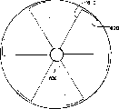
Fig. 2 is the schematic representation of a fluid column, and it has the tidal flow speed along the z axle, and it has been applied an angular velocity component;
Fig. 3 is the schematic representation that is used for extracting from fluid stream powered device of second embodiment of the invention;
Fig. 4 A has the fixedly schematic representation of the stator of dihedral blade for first converter plant corresponding with the equipment that is suitable for Fig. 1;
Fig. 4 B schematically shows the shape of individual blade of the stator of Fig. 4 A;
Fig. 5 shows the floor map of second converter plant;
Fig. 6 shows the side schematic view of second converter plant of Fig. 5;
Fig. 7 A is the schematic representation of the 3rd mode of execution of the present invention, and wherein, vertical tail is used for preventing to rotate outside the Road narrows of fluid guiding device;
Fig. 7 B schematically shows the positive sectional view of the fluid deflector of Fig. 7 A;
Fig. 7 C schematically shows the cross sectional view of anti-rotation member of the embodiment of Fig. 7 A;
Fig. 8 is the schematic representation of the 4th mode of execution of the present invention, and wherein, fluid guiding device is provided with on the both sides of suction port becoming a mandarin of each converter plant that is provided with.
Embodiment
Fig. 1 is used for extracting from fluid stream the schematic representation of powered device for one of first embodiment of the invention.This equipment comprises a fluid guiding device 100, a pipeline 200, a fluid driveable engine 300, a fluid collecting tank 400 and a pair of fluid deflector 500.
Owing to successional reason, the fluid displacement of unit time by the broad mouth of fluid guiding device 100 equals the fluid displacement of unit time by narrow (promptly flow and quicken constriction) of passage.Thereby, the liquid speed of the liquid speed during by constriction during greater than the inlet that enters fluid guiding device 100.According to Bernoulli's law, P+1/2 ρ v
2+ ρ gh=constant, wherein P is a hydrostatic pressure, and v is a liquid speed, and ρ is a fluid density, and g is a gravity accleration, and h is the height under the reference level (being horizontal plane in this case).Therefore the increase of liquid speed causes the effective pressure ρ gh of the contraction flow region office of liquid speed increase to reduce.To be expressed as primary fluid stream by the fluid stream of fluid guiding device 100.
Bernoulli's law is applied to usually and wherein exists in streamlined (laminar flow) mobile system.For the small flow speed in the passage of minor diameter, laminar flow occurs, and turbulent flow accounts for main flow in the big passage of flow velocity.But even the flowing of constriction of passing in the passage is turbulent shape, pressure will descend along with the increase of bulk velocity, and is described as Bernoulli's law.This is because for the fluid volume conservation, flows along with passages shrink must be quickened.By calculating and passing through direct experiment as can be seen, Bernoulli's law is applicable to turbulent flow, as it is applicable to linear flow.
Pressurized air quickens constriction along with main fluid (being water in this embodiment) by fluid and is collected by fluid collection tank 400.In this embodiment, fluid collection tank is positioned near the outlet afterbody of fluid guiding device 100, and the driving fluid in convection cell acceleration constriction downstream is collected.Fluid collection tank is provided with radial plate, is used for the eddy flow of partial offset introducing driving fluid at least.
Selecting fully in the embodiment, the afterbody of fluid guiding device is very long, driving fluid can be collected by the slit on fluid guiding device afterbody top, and this fluid guiding device is supplied with driving fluid the fluid collection tank of top by a discharge tail pipe that slit is connected to collecting tank.Select fully in the embodiment at another, an overlapping catch basin is set, the driving fluid that rises with convenient driving fluid (for example air) intercepting when fluid quickens emersion the constriction at different layers (promptly the distance with the axis of fluid guiding device is different).Each catch tray is supplied with homogeneous turbulence body collecting tank altogether with one from the narrow hole standpipe that catch tray rises.
Get back to the embodiment of Fig. 1, upwards flow through the part 200b of pipeline, and be supplied to turbo machine 300 subsequently from the pressurized air of fluid collection tank 400.Turbo machine 300 is by quickening the air driven that constriction flows to inlet 200c from air collection tank 400 through fluid.The air pressure P of the ingress of fluid guiding device 100
1=P
0+ ρ gh-p, wherein P
0Be barometric pressure, p quickens the suction pressure that constriction forms by fluid.As a comparison, the pressure in fluid guiding device outlet port is P
2=P
0+ ρ gh.Therefore, the air pressure of turbo machine both sides is ρ gh-(ρ gh-p)=p.Air is in pressure P
1Condition under be pumped to inlet 200c downwards, and in pressure P
2Condition under emersion from fluid guiding device again.If P
2>P
1, fluid driveable engine 300 just can be by pressure differential.But, the performance of turbo machine depends on pressure ratio P
2/ P
1, but not depend on pressure reduction.Though bigger pressure ratio makes efficient improve pressure ratio P
2/ P
1=4 has been enough.
As shown in Figure 1, produce a pressure head on the Venturi tube both sides.This pressure head forms by place an obstacle in water.This obstacle may itself form (embodiment of Fig. 8 as mentioned below is the same) by fluid guiding device 100.But, in the mode of execution of Fig. 1, pressure head is formed by a dam (not shown) that is positioned at the Venturi tube upstream.
The pressure P at inlet 200c place
1Should be enough high, so that air can not come out from solution.Because suction pressure p, the pressure at inlet 200c place may be less than barometric pressure P
0(P
0Approximate 10 meters hydraulic pressure greatly).Under atmospheric pressure, air in certain amount will be dissolved in the water.But if pressure is reduced to about 0.25 barometric pressure, at least a portion dissolved air can come out from solution.If pressure further is reduced to about 0.15 barometric pressure, and temperature is about 20 degrees centigrade, and then water can seethe with excitement.For the possibility (process that a kind of being known as " becomes air pocket (cavitation) ") that reduces the spontaneous formation of bubble, pressure should be at least 0.2 barometric pressure (being equivalent to 2 meters hydraulic pressure).This is meant P
1Should be the pressure that equals 2 meters depth of waters at least, in this case p=(P
0+ ρ gh-2 ρ g), wherein, P
0=1.013 * 10
5N/m
2ρ water=1000kg/m
3G=9.8m/s
2Therefore, h
1 atmosphere=P
0/ ρ g=10.34 rice hydraulic pressure.The needed pressure ratio of good steam turbine operation is at least 4.If this situation is satisfactory, then no matter the degree of depth of venturi system how, all can extract electric power, though higher pressure ratio makes turbine efficiency improve really.
Should be noted that suction is negative pressure, so the suction of-0.6 crust will be equivalent to the pressure of 1-0.6, if this suction is applied on a certain volume, it will unexpectedly be under the barometric pressure.If suction be-0.75 the crust (wherein, 1 crust is about a barometric pressure), and Venturi tube is positioned at the h=7.5m place, then air will be inhaled into Venturi tube, but suction will just in time be offset hydrostatic pressure, the air that therefore enters at input end can not do work (suppose the afterbody disappearance of air in Venturi tube 100).But if Venturi tube just is placed on water surface below, then hydrostatic pressure can be ignored.In this case, if air guiding by a turbo machine and feed back to Venturi tube opening as input end subsequently, then can obtain 1/0.25 pressure ratio (P
2/ P
1).
If h=12m, then the numerical value of suction must be less than 19.5m, (because the P otherwise air will come out from solution
1Can be too low).In this case, the air of input end is 0.25 crust (or be equivalent to 0.25 barometric pressure or 2.5m water), and the air of output, P
2=10m (barometric pressure)+12m (degree of depth h)=22m.Therefore pressure ratio will be 22/2.5.
Suppose that Venturi tube only working under the available suction pressure by Bernoulli effect.As typical situation, suppose that the venturi diameter at the wideest point of passage place and the ratio of the venturi diameter that the narrowest point of passage (Road narrows) is located equal 4.If water enters the opening of Venturi tube under the water velocity v (belonging at a high speed) of 5m/s for tidal flow then, then water will be 20m/s by the speed of Road narrows.Suction is drawn by following formula, 0.05v
2=0.05 * 400=20m, this value approximates 2 barometric pressure.Suppose that 5m/s is high-speed for tidal flow, and by Venturi tube obstacle is positioned over tidal flow and certainly will reduces flowing velocity.Therefore should be understood that 2 atmospheric suction pressures are the upper limits by utilizing Bernoulli effect itself to reach only.In order to obtain good power transmission efficiency, need be higher than 2 atmospheric suction pressures.Obviously, this need than only by Bernoulli effect obtainable bigger suction pressure.
In the device of Fig. 1, just can obtain big suction pressure before tidal flow enters fluid guiding device 100 by using converter plant 500 that moment of momentum just was applied on the tidal flow that a part enters.Fig. 2 schematically shows a columnar fluid, and it has one along the tidal flow speed that has applied the z axle of an angular velocity component.In Fig. 2, same as in figure 1, converter plant 500 is used for giving fluid with moment of momentum.But converter plant 500 is can be any, because it is believed that eddy flow can Lock-in in the passage of Venturi tube, reason is that its unstability in fluid stream is less.As described below, Fig. 3 is for relying on the specific embodiment of spontaneous formation vortex.
In the embodiment in figure 1, converter plant 500 is equivalent to a stator with fixedly dihedral blade of static array as schematically shown in Figure 4.This stator structurally with jet engine on turbofan similar, though the blade of this stator is less.The shape approximation triangle of each blade has a very little drift angle, and has a rising edge 610 and a trailing edge 620.The center hole 630 of ventilation duct 220c in stator enters.The individual blade that Fig. 4 B schematically shows from leg-of-mutton bottom, the summit is looked away from eyes.Look that from this direction blade is rendered as a short arc of a great circle, this arc forms from a rising edge 610 to one trailing edges 620 of a particular vane.The main fluid that enters is parallel to the surface of blade at first, Yi Bian but subsequently with respect to the curvature deflection of pressing arc.Like this, the main fluid that flows through along it passed to moment of momentum by converter plant.This blade is given introducing water with moment of momentum r ω (wherein, r is the circular cross-section radius of fluid), and solid rotates (promptly rotate in the mode of unanimity, thereby for all water that enter system, angular velocity being definite value) as one basically to make it.The advantage of the blade that uses static vane but not be connected with turbo machine is that stator blade can be taken simply and take out and be used for cleaning from water.Because this structure is dirty in the typical undersea environment that energy extraction apparatus is installed, therefore may need cleaning.Selecting fully in the mode of execution, using the suitable converter plant of shape of not establishing blade.Such selecting fully in the mode of execution, the residing position of solid body makes that it plays inhibition to main fluid when main fluid enters fluid guiding device 100.If this solid body has hindered a HALF OPENING of fluid guiding device, but be positioned at a distance (being a distance of opening upstream) away from opening, the axis incoming fluid that fluid potential must be only be parallel to constriction from a side quickens to go the constriction.When main fluid enters fluid acceleration constriction, this will give a rotational component to main fluid.Because eddy current is rotated in a clockwise direction (because sense of rotation of the earth) on the Northern Hemisphere naturally, therefore can determine the opening side that gets clogged like this.
In Fig. 2, the tidal flow of introducing has a linear velocity v along the z axle.Supposing does not have frictional loss, and (it v) is identical knowing resultant velocity thus by inference to the kinetic energy of the water column before and after the deflection, though the axial component v of speed
RzReduce and the tangential component v of speed
RtBe endowed water column.Because energy is saved, thereby v
2=v
Rz 2+ v
Rt 2The angular displacement of fluid column causes producing a centrifugal force in the non-inertial coordinate system of fluid.This centrifugal force produces a pressure reduction, thereby the pressure between fluid column center and the periphery increases.
At the radius r place, the pressure increment that causes owing to centrifugal force can easily be expressed as and equal v
Rt 2/ 2g=r
2ω
2/ 2g.The glassware for drinking water that converter plant 500 has made all enter fluid guiding device 100 has the angular velocity omega of substantial constant, and beginning at the opening that enters fluid guiding device 100 at least is like this.Therefore, the pressure increment that causes owing to centrifugal force is in circumference place maximum, that is maximum near the wall by the formed passage of inlet horn of fluid guiding device 100.When fluid at v
RzEffect under when advancing fluid accelerating part by passage, the radially relevant pressure increment that causes owing to centrifugal force at least local equalize this pressure drop (relevant) with Bernoulli effect, this pressure drop causes v owing to quicken constriction by fluid
RzIncrease and occur.Therefore, give the acceleration that fluid quickens the water in the constriction and reduce, big or small consistent with centrifugal force under the relevant radii condition in radially relevant mode.
Fluid quickens pressure gradient relevant with centrifugal force in the constriction and makes the passage in the zone of constriction narrow down artificially with the antagonism of Bernoulli effect pressure drop associated.Therefore, the v in the zone of eddy current axis
RzSignificantly greater than near the v the channel wall
Rz
Consider now the situation that can occur when the fluid of rotating flow scapus by fluid guide structure 100 among Fig. 2 quickens constriction.Suppose that fluid column rotates and ignore the influence of any secondary vortices that may form basically as a solid, moment of momentum will inevitably arrive preservation when channel narrows.For for the solid of angular velocity omega rotation, moment of momentum and r
2ω is proportional, therefore if moment of momentum is saved, and r then
1 2ω
1=r
2 2ω
2Because radius r reduces (r when fluid is mobile towards the narrowest point of fluid acceleration constriction
2<r
1), angular velocity must increase (ω
1>ω
2) so that preserve moment of momentum.
But because centrifugal pressure radially increases, thereby fluid motion produces a resistance, therefore when channel narrows, is forced to towards center flow from the fluid of passage exterior domain.Owing to the inwardly mobile moment of inertia that causes of whole fluid reduces also to make angular velocity to increase (rotating similar with her arm traction faster with realization with the skater) to preserve moment of momentum.Suppose r
2ω is a definite value, and the supposition centrifugal pressure is by r
2ω
2/ 2g determines, thereby centrifugal pressure equals k ω, and wherein k is a constant.Therefore, because ω increases manyly for the bigger r of less r, thereby for little r, centrifugal pressure also increases manyly.
Therefore, because negative feedback mechanism, be applied thereto and cause in passage, forming vortex so angular velocity is entered the fluid guiding device place in main fluid, thereby the water of rotation forms an enclosure effect at the long radius place.Then, this enclosure effect makes whole fluid move towards the center of fluid, thereby makes moment of inertia reduce and order about angular velocity for the conservation of angular momentum and increase.The centrifugal pressure that the increase of acceleration further makes fluid quicken near constriction wall (promptly at the long radius place) increases.
This positive feedback mechanism operation is substantially zero (at least in theory) until the pressure along axis, so that can not obtain further pressure drop.The axis that this positive feedback mechanism of bringing out by the incoming fluid stream of an angular velocity being passed to the opening that enters fluid conducting unit 100 causes the longshore current body to quicken constriction produces a big suction pressure.No matter primary fluid velocity v and fluid quicken the degree of depth h that the contraction flow region branch is positioned at and how all can obtain this big suction pressure.In first specific embodiment of Fig. 1, fluid flow deflectors 500 is used for giving the main fluid that enters the Venturi tube opening with moment of momentum.
Compare the obtainable suction by only utilizing Bernoulli effect (promptly not rotating main fluid), the fluid of moment of momentum being passed to the opening that enters Venturi tube 100 makes suction obviously increase.Have when rotatablely moving when this enters fluid, the hydrostatic pressure at inlet 200c place can be overcome easilier, thereby Venturi tube 100 can be positioned at bigger degree of depth h place, utilizes service pump that air is pumped into inlet 200c downwards and need not to rely on.If the opening in Venturi tube 100 is directly introduced driving fluid (for example air) in the main fluid (for example water) of a nonrotational fluid, move towards the axial direction of Venturi tube not ordering about air, so it with the disturbance current, makes it become more disorderly and it is increased greatly in the Road narrows of Venturi tube 100 and the loss in the afterbody.
As mentioned above, though converter plant 500 is enough to cause at leisure that by the positive feedback mechanism of utilizing fluid to quicken in the constriction vortex forms, but converter plant is not requisite for obtaining eddy current, even because main fluid may also be enough to bring out positive feedback mechanism by the little imbalance in the flowing of Venturi tube 100.Therefore, of the present invention one select mode of execution fully and comprise all structure members except fluid flow deflectors 500 among Fig. 1.In this mode of execution, the residing position of the air inlet parts 200c of pipeline makes it consistent with the axis of the eddy current that forms in Venturi tube 100 basically.Naturally the axis of the eddy current of Xing Chenging needn't be consistent with the axis of the mobile acceleration constriction of Venturi tube.But, the symmetry properties of venturi channel is how to form naturally with the major decision eddy current, thereby if the cross-section area of passage is the rotation symmetry, the axis of eddy current and passage itself can overlap basically.In addition, the position of entrance 200c can be adjusted at the scene aliging with the axis of eddy current basically, thereby makes driving fluid flow through Venturi tube.But even conduit air inlet 200c just in time overlaps with the running shaft of main fluid, air will be all the time be " squeezed. " towards the direction of axis, supposes that this extrusion effect controlling the buoyancy of air.This is because if the water body rotation then has minimum pressure all the time on the axis.
Fig. 3 is the schematic representation that is used for extracting from fluid stream powered device of second embodiment of the invention in this embodiment.Another embodiment that this second mode of execution is an embodiment does not wherein form eddy flow with fluid deflector.In addition, in this embodiment, driving fluid (air) is not to supply with the opening of Venturi tube by a part of pipeline (200a among Fig. 1,200c) of being supplied by the outflow opening of turbo machine 300.On the contrary, the driving fluid inlet is an eddy current 120 that forms naturally, and it extends downward the opening of Venturi tube 100 from the water surface.Air from the atmosphere of the water surface be inhaled into eddy current in intracardiac, and bubble is transferred in the eddying current of eddy current, this eddy current orders about their openings down to Venturi tube 100, so air quickens constriction by fluid and is inhaled into air collection tank 400.As can be seen from Figure 3, the radius R of water surface place eddy current
vRadius than the eddy current of the opening of Venturi tube is much bigger.Pressurized air from the air collection tank of Venturi tube 100 exhausts upwards by a part of pipeline 200 and enter turbo machine 300 mobilely be used to drive turbo machine.But mode of execution among Fig. 3 and the difference among Fig. 1 are that expanded air flows out the opening that Venturi tube 100 is got back in not recirculation downwards from turbo machine 300.
In embodiments of the present invention, for example shown in Fig. 1 and 3 meaning those mode of executions, the axial pressure (being near the pressure the eddy current axis) that the fluid of Venturi tube 100 quickens in the constriction may trend towards zero, this is the result who flows owing to rotating fluid, and irrelevant at undersurface degree of depth h with fluid guide structure and inlet nozzle 200c.Therefore, this device is suitable for deep-water operation.Embodiments of the present invention utilize the rotational flow of the water in the Venturi tube to obtain big suction pressure, this means that the exhaust pressure of turbo machine will be lower.Mean for deep-water operation pressure ratio (P even can obtain bigger suction pressure
2/ P
1) be 4 also to be feasible.
Embodiments of the present invention generally adopt the single stage of pressure amplifying system, and this pressure amplifying system is quickened constriction by fluid to be provided.Driving fluid (for example air) directly is transferred into Venturi tube 100.Venturi tube 100 need not any nozzle or inlet comes valid function, this means that flow resistance is reduced.Because main fluid flows through Venturi tube fast, dirt seldom can become a problem in these systems.
Quicken constriction and the caused positive feedback mechanism of comprehensive function of the eddy flow given by fluid guiding device makes and can obtain the required suction pressure of effective steam turbine operation really by fluid.If the fluid guiding device 100 residing degree of depth are enough, then driving fluid (being air in this embodiment) will fully be compressed, thereby can be used for driving turbo machine 300.On the contrary, if fluid guiding device only is positioned at a bit of distance under water, air turbine 300 passes through the suction that is produced but not the pressurized air that passes through to be produced is driven effectively.Because it is less (because water is 0.75 * 10 by sucking available pressure reduction
5N/m
2About suction pressure under begin to bubble), thereby air turbine must under the pressure reduction condition about 1 barometric pressure, work, this is may not can very efficient.Therefore, when device be positioned at next enough degree of depth of horizontal plane (h>>12m) operate on it and be better than shallow water operation.
Generally speaking, the efficient of fluid guiding device 100 and its area are than relevant.The ratio that quickens the narrowest point (being Road narrows) of constriction at cross section and fluid by the widest position of fluid guide structure 100 formed passages is the area ratio.Typical area ratio will for example be 3.5, and wherein throat diameter is 0.75m.The area ratio will be looked engineering, weight and cost element and suitably select.Usually, the area of fluid guiding device is than more little, and efficient is high more.But the area of selecting at the maximum efficient of possibility is than the speed of the inlet air flow that will depend on fluid.Since the cross-section area that the positive feedback mechanism that is caused by guide plate 500, fluid are quickened constriction Road narrows place with respect to the wideest some place needn't be very big.Road narrows are wide more, and then the flow resistance of main fluid is more little, thereby wherein use the device of positive feedback mechanism to be improved with respect to well known device efficient.
In view of the radius of cross section is very little in theory along the area of low pressure of the axis that is quickened the passage that constriction forms by fluid.So driving fluid enters the radius of the suction lead 200c of fluid guide structure also should less (0.1m or littler).Discharge through the minor diameter outlet for the ease of fluid, the viscosity of driving fluid should be lower.The driving fluid of air and so on is suitable for being discharged by minor diameter outlet, and the viscosity of water is then too high.Because the quality of the driving fluid by wherein in the power of being carried by turbine and unit time is relevant, so air density is for determining that exporting energy is a key factor.Because water level is dark more, air density is then high more, so if Venturi tube 100 is positioned at bigger degree of depth place, the suction port 200c of Venturi tube 100 can have littler diameter.In order to make the maximization of energy extraction device working efficiency, driving fluid should be discharged, thereby it can directly enter the area of low pressure along the central shaft of eddy current.If but driving fluid away from axis supply, it should be by the pressure reduction that formed by rotation towards axis drives.
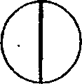
Fig. 5 schematically shows the planimetric map that another of converter plant 500 of Fig. 1 may structure.In this embodiment, converter plant is formed by static wall 510,512, and it hinders current and enters (left side from figure enters).One of them wall 510 is L shaped structure, and another is a upright walls 512.By the slit between L shaped wall 510 and the upright walls 512, and make eddy current 120 in by the space that wall limited, form from the water that enters stream by the obstruction that the wall convection cell provides.In this embodiment, the sense of rotation of eddy current is by the clockwise direction shown in the arrow.Fig. 6 shows the profile of the static wall converter plant structure of Fig. 5.In this embodiment, the sense of rotation of main fluid is by cross mark (the most close wall 512) and some mark (the most close wall 510) expression, and cross mark represents that main fluid flows in the plane of this page, and the some mark represents that main fluid flows out from the plane of this page.Static wall converter plant shown in Fig. 5 and 6 is applicable in the more shallow water.
Fig. 7 A schematically shows the 3rd mode of execution of energy extraction apparatus.In this embodiment, fluid collection tank 400 is positioned at the afterbody of Venturi tube.Fluid collection tank 400 comprises a catch tray 412, this catch tray extends in the passage of Venturi tube, and link to each other with collecting tank 410 through a throat 414, this throat runs through the slit in the Venturi tube rear main body and enters in the venturi channel downwards.This equipment comprises that one is positioned at the elementary converter plant 520 of Venturi tube opening, it gave fluid with rotation when fluid quickened constriction 110 when fluid enters, and comprised that a fluid between elementary converter plant 520 and collecting tank 410 quickens constriction 110 anti-rotation member 120 in addition.Anti-rotation member 120 is used for preventing quickening fluid that constriction the comes out direction rotational flow towards driving fluid catch tray 412 from fluid.Fig. 7 B has schematically shown the positive sectional view of elementary converter plant 520.The structure of deflecting blade identical with described in Fig. 4 A and the 4B.Fig. 7 C schematically shows the cross section of anti-rotation member 120, this member comprises a vertical tail, so that small part stops the rotation before it further flows to fluid collection tank 412 along the afterbody of Venturi tube 100 of the fluid that quickens the constriction emersion by fluid.Supply with the opening of Venturi tube from the pipeline of the air in the water surface through leading to suction tude 210.
The suction tude 210 of Venturi tube opening will be usually at barometric pressure P
0Under the condition, the air tank 410 that is positioned at the depth H place then is in (P
0+ ρ gH
Groove) pressure condition under.May need to apply little malleation P inlet, wherein a P at inlet 210 places
Inlet<<ρ gH
Groove, enter in the inlet duct to order about air, and by Venturi tube 100.Air flow to suction tude 210 from collecting tank 410 and is used to drive turbine 300.
A kind of being used for that Fig. 8 schematically shows in the four embodiment of the invention extracted powered device from fluid stream.In this embodiment, fluid guiding device 100 has one and extends to quicken the central passage 116 that the constriction upstream forms a cone shape hole 112,114 at fluid.Venturi tube 100 is symmetry vertically, and suction port 200c is located substantially on the axis of cone shape hole 112,114.Same blade 522,524 is arranged in this cone shape hole, thereby passes this blade when water enters Venturi tube 100 when introducing.Blade 522,524 departs from the scope of passage slightly, and wherein their position makes the fluid that enters the Venturi tube main passage at water quicken to give water with moment of momentum before the constriction.Because formed suction in the passage of Venturi tube is so the pressure at suction port 200c place will be less than barometric pressure (such as 0.25P
0).
In the embodiment of Fig. 8, venturi channel 118 is upwards extended towards water surface direction from constriction 116 to afterbody, and the diameter of passage increases towards afterbody.Make the upstream and downstream in Venturi tube produce a horizontal plane difference by Venturi tube to introducing obstruction that water provided.This horizontal plane difference Δ H is commonly referred to as pressure head.Barometric pressure P
0Under air enter turbine 300, and flow down pipeline 220 to suction port 220c, it is transferred in water and is inhaled in the venturi channel 116 at this.Expand when venturi channel is passed in rise when the gassiness bubble makes progress, and make air and water flow through fluid acceleration constriction.This expanded air helps venturi channel is passed through in the water traction.Air flows through fluid and quickens constriction driving turbine 300.
In the specific embodiment of the present invention, fluid driveable engine 30 can be a kind of turbo machine of for example rotating vane turbine machine, or the Reciprocating engine of the piston in a kind of for example cylinder.In one embodiment, heat exchanger is positioned at the exhaust end place of fluid driveable engine, and receives the cool air that is produced by the expansion by fluid driveable engine.Heat exchanger is used for to the potential humid air of small part freeze-drying (being transferred in the current by fluid guiding device), and this humid air was received by fluid collection tank before it is cycled through fluid driveable engine.Before air is supplied with fluid driveable engine as charging it being carried out this process of drying is particularly useful in device for ships.Consider the example of turbo machine, when air expansion passed through turbo machine, any water vapor that is present in the air inflow will expand and cool off, thereby water vapor can freeze, and feasible salt from seawater steam proposes from solution.Unless take measures (for example dry air) in advance, then the high speed turbine blade may be by the attack of the crystal of ice and salt, thereby may cause quick erosion.
In another embodiment, heat exchanger links to each other with near the heat exchange circuit (for example chilled water circuit) of the equipment of aircondition one class.In this embodiment, equipment provided refrigerating function near the expansion of fluid driveable engine can be.Its favourable part also is to generate electricity from fluid driveable engine.
Claims (19)
1. one kind is used for extracting powered device from fluid stream, and described equipment comprises:
One fluid driveable engine;
One fluid guiding device, it is formed on the form that limits a passage in the flowing of main fluid, described passage has a fluid and quickens constriction, the shape of constriction makes and is accelerated when main fluid is quickened constriction through fluid, fluid guiding device is done the form that the main fluid that enters in pairs in the fluid acceleration constriction applies a swirl component, thereby when main fluid is quickened constriction through fluid, in main fluid, produce a radial pressure gradient;
One pipeline is used to guide driving fluid to flow, and driving fluid is different fluids with main fluid, and described pipeline is communicated with the passage fluid that a fluid driveable engine and a part have the fluid stream of acceleration;
Wherein the mobile driving fluid by described pipeline works with driving fluid driving motor through the eddy flow that fluid quickens the main fluid in the constriction, and described pipeline is delivered to described fluid guiding device with driving fluid, thereby driving fluid is inhaled into along the central axis of eddy flow basically.
2. equipment according to claim 1, it is characterized in that, described fluid guiding device comprises that at least one is positioned at the fluid deflector that described fluid quickens the constriction upstream, and described at least one fluid deflector is operationally passed to main fluid with moment of momentum.
3. equipment according to claim 2 is characterized in that, described at least one converter plant can be operated a substantially invariable eddy flow angular velocity is given all and enter the main fluid that fluid quickens constriction.
4. according to the equipment of claim 2 or 3, it is characterized in that described at least one fluid deflector is a static structure.
5. according to the equipment of one of claim 2 to 4, it is characterized in that described at least one converter plant is a stator, it has blade, and blade is arranged for gives the fluid that crosses blade with moment of momentum.
6. according to the described equipment of one of aforementioned claim, it is characterized in that, comprise at least one fluid collection tank, be used to collect the driving fluid that described fluid quickens the constriction downstream, described fluid collection tank is communicated with described fluid driveable engine fluid.
7. equipment according to claim 6 is characterized in that, described at least one fluid collection tank runs through the wall of described fluid guiding device and fluid is collected in the hole that enters described passage through one.
8. according to claim 6 or the described equipment of claim 7, it is characterized in that described fluid collection tank comprises an anti-rotation member, be used for stoping the incoming fluid rotation to small part.
9. according to claim 6 or the described equipment of claim 7, it is characterized in that, comprise that one quickens anti-rotation member between constriction and the described fluid collection tank at described fluid.
10. according to the described equipment of one of aforementioned claim, it is characterized in that, be provided with a single stage of pressure amplifying system of described fluid stream, described pressure amplifying system is quickened constriction by described fluid to be provided.
11., it is characterized in that described main fluid is made up of water according to the described equipment of one of aforementioned claim.
12., it is characterized in that described driving fluid is made up of air according to the described equipment of one of aforementioned claim.
13., it is characterized in that described fluid guiding device is positioned under the surface of described main fluid according to the described equipment of one of aforementioned claim, and described fluid driveable engine is positioned on the surface of described main fluid.
14., it is characterized in that described fluid driveable engine comprises a turbo machine according to the described equipment of one of aforementioned claim.
15. equipment according to claim 14 is characterized in that, comprises a driving fluid exhaust end place at described turbo machine, the heat exchanger in described driving fluid flow path.
16. equipment according to claim 15 is characterized in that, described heat exchanger is used to cool off described driving fluid.
17. equipment according to claim 15 is characterized in that, described heat exchanger is arranged for cooling off another driving fluid that is connected with an external equipment.
18. according to the described equipment of one of aforementioned claim, it is characterized in that, comprise that one is used at the obstacle of main fluid horizontal plane formation one across the difference of described fluid guiding device.
19. be used for extracting powered device by fluid stream, described equipment basically as in the literary composition with reference to as described in the accompanying drawing.
Applications Claiming Priority (4)
| Application Number | Priority Date | Filing Date | Title |
|---|---|---|---|
| GB0206623.1 | 2002-03-20 | ||
| GBGB0206623.1A GB0206623D0 (en) | 2002-03-20 | 2002-03-20 | Extracting power from a fluid flow |
| GB0229783.6 | 2002-12-20 | ||
| GBGB0229783.6A GB0229783D0 (en) | 2002-03-20 | 2002-12-20 | Extracting power from a fluid flow |
Publications (1)
| Publication Number | Publication Date |
|---|---|
| CN1643247A true CN1643247A (en) | 2005-07-20 |
Family
ID=28456021
Family Applications (1)
| Application Number | Title | Priority Date | Filing Date |
|---|---|---|---|
| CNA038064251A Pending CN1643247A (en) | 2002-03-20 | 2003-03-19 | Extracting power from a fluid flow |
Country Status (12)
| Country | Link |
|---|---|
| US (1) | US7150149B2 (en) |
| EP (1) | EP1488101B1 (en) |
| JP (1) | JP2005520984A (en) |
| CN (1) | CN1643247A (en) |
| AT (1) | ATE330120T1 (en) |
| AU (1) | AU2003216837B2 (en) |
| CA (1) | CA2478859C (en) |
| DE (1) | DE60306126D1 (en) |
| ES (1) | ES2266794T3 (en) |
| NZ (1) | NZ535961A (en) |
| PT (1) | PT1488101E (en) |
| WO (1) | WO2003081029A1 (en) |
Cited By (5)
| Publication number | Priority date | Publication date | Assignee | Title |
|---|---|---|---|---|
| CN102203410A (en) * | 2008-09-05 | 2011-09-28 | 德里克·詹姆斯·华莱士·麦克明 | Fluid power generator |
| CN103061964A (en) * | 2007-11-16 | 2013-04-24 | 自然能技术有限公司 | Power generator |
| CN108488029A (en) * | 2018-05-03 | 2018-09-04 | 广东电网有限责任公司 | Engine and generator |
| CN110792479A (en) * | 2019-11-07 | 2020-02-14 | 安徽伯华氢能源科技有限公司 | Hydrogen power generation system |
| CN114026325A (en) * | 2019-01-28 | 2022-02-08 | 阿尔瓦罗·法比安·比瑞西·阿祖百德 | Vector kinetic energy driver |
Families Citing this family (17)
| Publication number | Priority date | Publication date | Assignee | Title |
|---|---|---|---|---|
| GB2443195B8 (en) * | 2006-08-03 | 2010-05-05 | Verderg Ltd | Apparatus for converting energy from wave or current flows |
| JP5118138B2 (en) * | 2006-08-03 | 2013-01-16 | ヴェルドアルグ リミテッド | A device that converts energy from wave or flow flow using a pipe acting as a venturi pump |
| RU2347940C1 (en) * | 2007-09-21 | 2009-02-27 | Виктор Михайлович Лятхер | Wave power generation plant |
| US20100283248A1 (en) * | 2009-02-20 | 2010-11-11 | Moffat Brian L | Venturi based ocean wave energy conversion system |
| US8925313B2 (en) * | 2008-02-22 | 2015-01-06 | Brian Lee Moffat | Wave energy conversion apparatus |
| US8890352B2 (en) | 2008-09-05 | 2014-11-18 | Derek James Wallace McMinn | Power generator for extracting energy from a liquid flow |
| ES2373892B1 (en) * | 2009-01-27 | 2012-11-19 | Leopoldo Alandete Jurado | System for establishing a fluid stream by suction in a stream of water. |
| GB2471280B (en) | 2009-06-22 | 2011-08-31 | Hydroventuri Ltd | Apparatus and method for introducing a gas into a liquid |
| WO2011053978A2 (en) * | 2009-11-02 | 2011-05-05 | Cho Michael Y | System and method for water expulsion from underwater hydropower plant and hydropower plant associated therewith |
| US9194361B2 (en) | 2010-03-16 | 2015-11-24 | Verderg Ltd | Apparatus for generating power from fluid flow |
| DE102010020685A1 (en) * | 2010-05-15 | 2011-11-17 | Klaus Bußmann | River flow power plant has energy recovery device that is closed at low-pressure container and multiple spiral springs, where flow acceleration device is made of aluminum, steel or plastic |
| US20110278844A1 (en) * | 2010-05-16 | 2011-11-17 | Davis Sr Albert Hamilton | River High Pressure Energy Conversion Machine |
| US9567856B2 (en) * | 2010-06-30 | 2017-02-14 | Southern Alberta Institute Of Technology | Apparatus for extracting energy from a fluid flow |
| GB2503250B (en) | 2012-06-20 | 2015-05-27 | Verderg Ltd | Apparatus for converting energy from fluid flow |
| GB2524782B (en) | 2014-04-02 | 2016-04-20 | Verderg Ltd | Turbine assembly |
| GB201423276D0 (en) * | 2014-12-28 | 2015-02-11 | Mcnulty John | Cohering, concentrating convective current producer and methods of initiating and harnessing convective currents |
| EP3245654B1 (en) | 2015-01-15 | 2019-06-12 | General Fusion, Inc. | Apparatus and method for generating a vortex cavity in a rotating fluid |
Family Cites Families (9)
| Publication number | Priority date | Publication date | Assignee | Title |
|---|---|---|---|---|
| US680951A (en) * | 1901-01-31 | 1901-08-20 | Addison G Waterhouse | Hydraulic air-compressor. |
| US1005911A (en) * | 1911-01-21 | 1911-10-17 | Francis P Wilbur | Hydraulic-power air-compressor. |
| US4307299A (en) * | 1977-07-25 | 1981-12-22 | Norton Joseph R | System for generating electrical energy utilizing combined water power and combustible fuel sources |
| US4372113A (en) * | 1981-01-15 | 1983-02-08 | Ramer James L | Pipeline energy recapture device |
| US4868408A (en) * | 1988-09-12 | 1989-09-19 | Frank Hesh | Portable water-powered electric generator |
| US5142870A (en) * | 1988-11-08 | 1992-09-01 | Angle Lonnie L | Hydraulic compressor and fuel fired turbine apparatus |
| GB9009559D0 (en) * | 1990-04-27 | 1990-06-20 | Hydro Energy Ass Ltd | Hydro-electric power conversion system |
| GB9901350D0 (en) * | 1998-06-12 | 1999-03-10 | Imperial College | Apparatus for extracting power from a fluid flow |
| US6546723B1 (en) * | 2001-10-09 | 2003-04-15 | The United States Of America As Represented By The Secretary Of The Navy | Hydropower conversion system |
-
2003
- 2003-03-19 PT PT03712375T patent/PT1488101E/en unknown
- 2003-03-19 JP JP2003578734A patent/JP2005520984A/en active Pending
- 2003-03-19 US US10/508,316 patent/US7150149B2/en not_active Expired - Fee Related
- 2003-03-19 NZ NZ535961A patent/NZ535961A/en not_active IP Right Cessation
- 2003-03-19 DE DE60306126T patent/DE60306126D1/en not_active Expired - Lifetime
- 2003-03-19 WO PCT/GB2003/001171 patent/WO2003081029A1/en active IP Right Grant
- 2003-03-19 EP EP03712375A patent/EP1488101B1/en not_active Expired - Lifetime
- 2003-03-19 AT AT03712375T patent/ATE330120T1/en not_active IP Right Cessation
- 2003-03-19 CA CA2478859A patent/CA2478859C/en not_active Expired - Fee Related
- 2003-03-19 ES ES03712375T patent/ES2266794T3/en not_active Expired - Lifetime
- 2003-03-19 AU AU2003216837A patent/AU2003216837B2/en not_active Ceased
- 2003-03-19 CN CNA038064251A patent/CN1643247A/en active Pending
Cited By (9)
| Publication number | Priority date | Publication date | Assignee | Title |
|---|---|---|---|---|
| CN103061964A (en) * | 2007-11-16 | 2013-04-24 | 自然能技术有限公司 | Power generator |
| CN103061964B (en) * | 2007-11-16 | 2015-05-13 | 自然能技术有限公司 | Power generator |
| CN102203410A (en) * | 2008-09-05 | 2011-09-28 | 德里克·詹姆斯·华莱士·麦克明 | Fluid power generator |
| CN102203410B (en) * | 2008-09-05 | 2014-12-03 | 德里克·詹姆斯·华莱士·麦克明 | Fluid power generator |
| CN108488029A (en) * | 2018-05-03 | 2018-09-04 | 广东电网有限责任公司 | Engine and generator |
| CN108488029B (en) * | 2018-05-03 | 2024-02-13 | 广东电网有限责任公司 | Engine and generator |
| CN114026325A (en) * | 2019-01-28 | 2022-02-08 | 阿尔瓦罗·法比安·比瑞西·阿祖百德 | Vector kinetic energy driver |
| CN110792479A (en) * | 2019-11-07 | 2020-02-14 | 安徽伯华氢能源科技有限公司 | Hydrogen power generation system |
| CN110792479B (en) * | 2019-11-07 | 2020-07-28 | 安徽伯华氢能源科技有限公司 | Hydrogen power generation system |
Also Published As
| Publication number | Publication date |
|---|---|
| ATE330120T1 (en) | 2006-07-15 |
| EP1488101A1 (en) | 2004-12-22 |
| WO2003081029A1 (en) | 2003-10-02 |
| ES2266794T3 (en) | 2007-03-01 |
| NZ535961A (en) | 2006-11-30 |
| AU2003216837B2 (en) | 2008-07-31 |
| AU2003216837A1 (en) | 2003-10-08 |
| US7150149B2 (en) | 2006-12-19 |
| US20050081517A1 (en) | 2005-04-21 |
| EP1488101B1 (en) | 2006-06-14 |
| JP2005520984A (en) | 2005-07-14 |
| PT1488101E (en) | 2006-10-31 |
| CA2478859C (en) | 2010-08-17 |
| CA2478859A1 (en) | 2003-10-02 |
| DE60306126D1 (en) | 2006-07-27 |
Similar Documents
| Publication | Publication Date | Title |
|---|---|---|
| CN1643247A (en) | Extracting power from a fluid flow | |
| US8801359B2 (en) | System and method for extracting power from fluid using a Tesla-type bladeless turbine | |
| US10920793B2 (en) | Energy recovery-recycling turbine integrated with a capillary tube gas compressor | |
| US9322385B1 (en) | Hydro vortex enabled turbine generator | |
| CN1105238C (en) | Ocean wave energy extraction | |
| EP1492956B1 (en) | Extracting power from a fluid flow | |
| AU750680B2 (en) | Apparatus for extracting power from a fluid flow | |
| WO2005075818A1 (en) | Process and device for converting hydraulic energy into mechanical energy | |
| US7645115B2 (en) | System, method, and apparatus for a power producing linear fluid impulse machine | |
| CN103452741B (en) | Offshore hydroelectric generation platform | |
| US8376699B1 (en) | Vortex hydro turbine | |
| CN203404014U (en) | Low-head hydraulic and pneumatic conversion device | |
| CA2647773A1 (en) | Multiple augmented turbine assembly | |
| EP3748153A2 (en) | Wind-based electrical power generation system | |
| JPH05141340A (en) | Hydraulic power generation in small flow velocity and large quantity flowing water | |
| RU2084692C1 (en) | Method and device for converting flow energy into mechanical or electric energy | |
| CN109798216A (en) | A kind of perpendicular axis type hydraulic turbine with separate type speedup conflux plate | |
| CN102797614A (en) | Spout pipe gravitational wave generating equipment | |
| ZA200100329B (en) | Apparatus for extracting power from a fluid flow. |
Legal Events
| Date | Code | Title | Description |
|---|---|---|---|
| C06 | Publication | ||
| PB01 | Publication | ||
| C10 | Entry into substantive examination | ||
| SE01 | Entry into force of request for substantive examination | ||
| C02 | Deemed withdrawal of patent application after publication (patent law 2001) | ||
| WD01 | Invention patent application deemed withdrawn after publication |