Background technology
A kind of plate welding structure is disclosed in Japanese laid-open patent application publication number No.2002-133809.Accompanying drawing 13 to 15 illustrates this traditional plate welding structure.Figure 13 is the side view of cut-away section, illustrates the part of head suspension 101 before welding; The cross sectional view of Figure 14 for amplifying, illustrate the pith in Figure 13; The cross sectional view of Figure 15 for amplifying, illustrate the part state welding after identical with diagram in Figure 14.
Head suspension 101 has a carrier bar 103 and a substrate 105.
Described carrier bar 103 comprises a rigid member 107 and an elastic component 109, is used for load is applied to a slide head body (not shown) that is arranged at carrier bar 103 front ends.Elastic component 109 is made by elastic plate 111.Described elastic plate 111 has a base portion that is held between substrate 105 and stiffening plate 113, and by laser bonding, is fixed between substrate 105 and stiffening plate 113.As shown in Figure 13 and Figure 14, carry out laser bonding by form aperture 115 on stiffening plate 113.Laser beam is aimed at each aperture 115, forms weld part W as shown in figure 15.
Substrate 105 has the projection 117 that matches with the support arm of carriage.
Aperture 115 forms on stiffening plate 113, makes overlapping substrate 105, elastic plate 111 and stiffening plate 113 to arrive together by more low-energy LASER BEAM WELDING.The energy that reduces laser beam can suppress the generation of splashing effectively.
Yet, to aperture 115 Emission Lasers bundles, stiffening plate 113 and laser beam accurately need to be located.This will limit its large-scale production.
In order to address this problem, aperture 115 can be amplified, make laser beam can be easy to aim at each aperture.But as shown in figure 16, undue amplification aperture 115 can cause that aperture 115 and weld part W's is disproportionate.At this moment, even the intensity of weld part W is enough, but the gap 119 that is formed between weld part W and hole 115 but makes naked eyes be difficult to pick out defective welding from acceptable welding.
In addition, the existence in gap 119 may be accumulated the inert gas that is difficult to remove, even for the nitrogen that is blown into when the laser bonding.So,, through the reaction of air and laser, will change color around gap 119.
, if be not used for the aperture 115 of laser bonding, so just must use than the laser beam of macro-energy.This can cause the distortion of stiffening plate 113 etc. in the generation of splashing and welding process.
Summary of the invention
A target of the present invention is to provide a kind of plate welding structure and head suspension, can relax the requirement to the laser beam accurate positioning, increases mass production capabilities, suppresses the generation of splashing, and prevents the distortion of stiffening plate in welding process.
In order to reach above-mentioned target, a first aspect of the present invention provides a kind of plate welding structure or head suspension, have the coating portion that forms on a certain given sheet material wherein, have a weld part on this coating portion, can sheet material be welded together by laser beam irradiation.
First aspect forms a coating portion on a certain given sheet material therein, and to this coating portion Emission Lasers bundle, sheet material is welded together.This structure can allow to reduce the energy of laser beam, and has prevented that laser bonding from causing the generation of splashing and the distortion of sheet material.
Coating portion can be than relative larger of welding portion.Even there is no in this case, the gap of air accumulation between coating portion and welding portion yet.Thereby prevented that the color that welding causes from changing.
The ratio welding portion that coating portion can be made is large.Make laser beam be more prone to respect to the location of coating portion.This has the advantage of batch production.
A second aspect of the present invention forms coating portion by the recess that forms on given plate surface.This recess has an opening at the edge of sheet material, make recess lead to the outside of plate surface.
According to a second aspect of the present invention, in laser bonding, inert gas (as nitrogen) when blowing to coating portion, just can flow to outside plate surface from the opening at edge along the recess part.Thereby prevented that air from, in the accumulating of coating portion, further positively having prevented the change of the product color that laser bonding causes.
A third aspect of the present invention forms coating portion by the recess that forms on given plate surface, and this recess leads to the outside of plate surface by a through hole that penetrates sheet material that forms on non-welding position.
According to the third aspect, in laser bonding, inert gas-as nitrogen-when blowing to coating portion, just can discharge to the outside of sheet material by penetrating through hole that sheet material forms.Thereby prevented that air from, in the accumulating of coating portion, further having prevented the change of the product color that laser bonding causes really.
A fourth aspect of the present invention forms coating portion by the recess that forms on given plate surface, and this recess, greater than welding portion, makes it can lead to the outside of plate surface around weld part.
According to fourth aspect, in laser bonding, inert gas (as nitrogen) when blowing to coating portion, just can discharge to the outside of sheet material around welding portion.Thereby prevented air in the accumulating of coating portion, further certain change that has prevented the product color that laser bonding causes.
A fifth aspect of the present invention forms above-mentioned coating portion by partially-etched or extruding.
According to the 5th aspect, coating portion can easily be made.
A sixth aspect of the present invention forms the rigid member of carrier bar and elastic component respectively, then rigid member is connected to the first side of elastic component, then with superimposed being connected on stiffening plate of the second side of elastic component.
According to the 6th aspect, the material of the rigid member of carrier bar and thickness are not subjected to the restriction of elastic component.This makes the material of rigid member and thickness can be independent of outside elastic component, selects according to its demand separately, thereby can meet rightly the required performance of head suspension.
For example, the rigid member of carrier bar can be made by slab, to remove the Forging Process that forms bent limit or curved rib on rigid member.In addition, slab has improved the rigidity of rigid member, has improved simultaneously its air resistance.Thereby, reduced disk has occurred when the rotation of head suspension hard disk drive high speed has been installed turbulent flow, and prevented vibration-generating when head suspension is in place.
Description of drawings
Fig. 1 is decomposition diagram, has partly illustrated the head suspension that there is no flexible element according to first embodiment of the invention;
Fig. 2 is vertical view, illustrates the welding position according to the head suspension of the first embodiment;
Fig. 3 is side view, illustrates the part according to the head suspension of the first embodiment;
Fig. 4 is amplification plan view, illustrates one of them welding position according to the first embodiment;
Fig. 5 is the sectional view that dissects along SA-SA line in Fig. 2;
The sectional view of Fig. 6 for amplifying, this sectional view is to dissect along SB-SB line in Fig. 2, and there is no elastic plate;
Fig. 7 is vertical view, illustrates the stiffening plate according to the first embodiment;
Fig. 8 is vertical view, illustrates the stiffening plate according to a kind of modification of the first embodiment;
Fig. 9 is vertical view, illustrates the stiffening plate according to the another kind of modification of the first embodiment;
Figure 10 is vertical view, part illustrate stiffening plate according to another modification of the first embodiment;
Figure 11 is skeleton view, illustrates the head suspension that there is no flexible element according to second embodiment of the invention;
Figure 12 is skeleton view, has partly illustrated head suspension shown in Figure 11;
Figure 13 is the cut-away section side view, illustrates the head suspension before welding in correlation technique;
Figure 14 is amplification view, illustrates the part before welding in correlation technique;
Figure 15 amplification view, illustrate with the situation after part welding;
Figure 16 is amplification plan view, illustrates in correlation technique the welding situation after aperture strengthens.
Embodiment
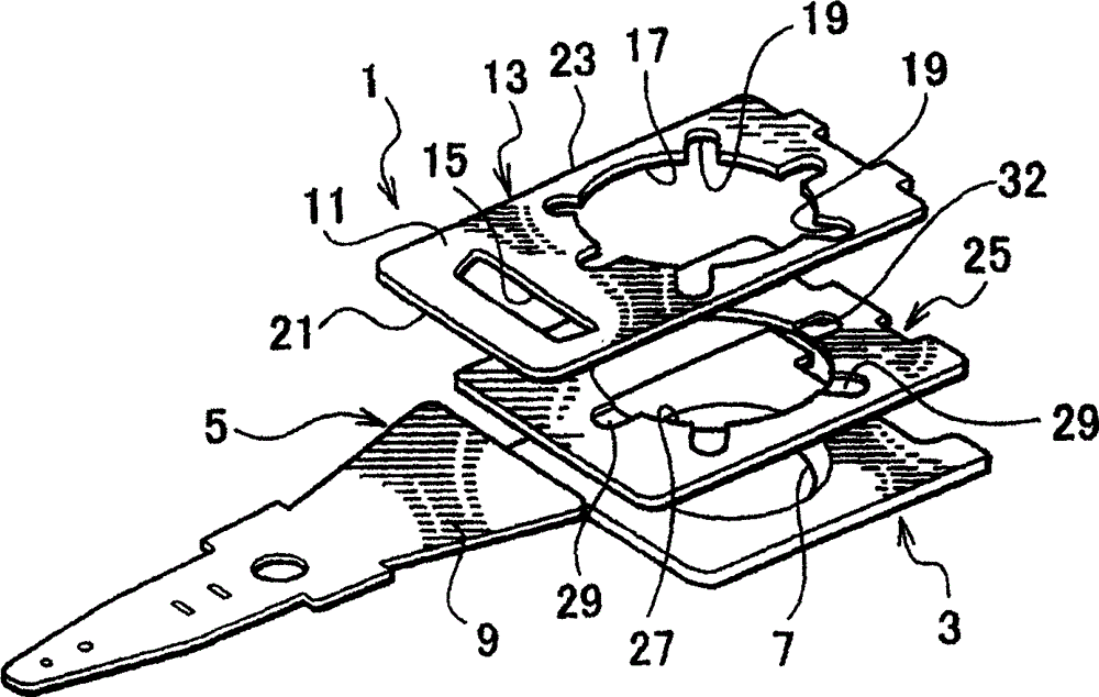
Fig. 1 is decomposition diagram, has partly illustrated the head suspension that there is no flexible element according to first embodiment of the invention.Head suspension 1 has substrate 3 and carrier bar 5.
Substrate 3 is connected on the support arm of carriage.Substrate 3 can be crushed to by corrosion resistant plate.According to the present embodiment, the thickness of substrate 3 is 0.2mm.Substrate 3 has the projection 7 of an integral body, from the side surface (basal surface Fig. 1) of substrate 3, protrudes.Projection 7 matches with a mating holes on the carriage support arm, and by riveting method, fixes, and that is to say, by the hard sphere that passes wherein, fixes.
Carrier bar 5 comprises a rigid member 9 and an elastic component 11.
According to the present embodiment, rigid member 9 can be by such as stainless steel, making, and have the thickness of about 0.1mm.Rigid member 9 can also be made as the alloy of aluminium (Al), titanium (Ti) or synthetic resin by containing light metal (than the light metal of Fe), with the weight that alleviates head suspension and improve its rigidity.
Rigid member 9 also can be made by compound substance (clad material), and this kind material comprises two-layer or two-layer above material, and these materials comprise light metal, as aluminium, titanium or contain the alloy of these light metals; And other metal, as stainless steel.
Elastic component 11 is made by the elastic plate 13 that is independent of rigid member 9., due to this structure, make and can select respectively suitable material and thickness for rigid member 9 and elastic component 11, thereby easily meet the desired high stiffness characteristics of rigid member 9 and the desired low spring constant characteristic of elastic component 11.For example, elastic component 11 makes to provide stable low spring constant by certain finish rolling material.
Elastic plate 13 can be made by the elastic stainless steel thin plate, and its thickness is for example 0.04mm.Elastic plate 13 has opening 15 and a through hole 17, and they are by such as etching or precise extrusion, forming.
The opening 15 of elastic plate 13 has partly been realized low bending stiffness (spring constant), and has formed elastic component 11 between substrate 3 and rigid member 9.One end of elastic component 11, namely its front end 21 puts on the cardinal extremity of rigid member 9, and by the mode as laser bonding or connection, is fixed in the above.The other end of spring 11, namely the cardinal extremity 23 of elastic plate 13 puts on stiffening plate 25, and by the mode as laser bonding or connection, is fixed in the above.
Through hole 17 is used to pass the ball for riveted joint.Groove 19 with specific interval form in through hole 17 around.
Stiffening plate 25 forms the mainboard of carrier bar 5 together with rigid member 9.Stiffening plate 25 and rigid member 9 can form by compacting.According to the present embodiment, stiffening plate 25 and rigid member 9 have identical material to make, and have identical thickness.
Stiffening plate 25 has through hole 27, and the through hole 17 on its diameter and elastic plate 13 is roughly the same.Through hole 17 and 27 diameter are greater than the inside diameter of projection 7.
Coating portion 29 with fixing interval form in through hole 27 around.The position of the groove 19 on this coating portion 29 and elastic plate 13 is corresponding, and has the shape and size roughly the same with it.
Stiffening plate 25 is stacked on substrate 3.The solder joint that is contained in each coating portion 29 is welded together with substrate 3 and stiffening plate 25 through the irradiation of laser beam.
Add a flexible element (not shown) by modes such as laser bonding or connections on rigid member 9.This flexible element by metal-based layer (as elastic stainless steel, rolling plate), form in the electric insulation layer on metal-based layer surface and the conduction path that forms on insulation course forms.One end of conduction path is connected with the terminal on being arranged at a body, and the other end is connected with the terminal that is used for read output signal.Flexible element has a ligule device that the slide head body is installed.
The solder joint vertical view that Fig. 2 connects together substrate 3, stiffening plate 25 and elastic plate 13 for diagram.Dash area in Fig. 2 represents coating portion 29.Fig. 3 is the side view of Fig. 2.
In Fig. 2 and Fig. 3, head suspension 1 comprises substrate 3, stiffening plate 25 and elastic plate 13, and they are mutually stacked in order.Elastic plate 13 and stiffening plate 25 be solder bond on the position beyond coating portion 29.According to the present embodiment, they utilize and are laser-welded to together at 3 solder joint W1 along opening 15 and on two solder joint W1 at the edge 2 that is positioned at through hole 17 opposite sides.
Substrate 3 and stiffening plate 25 are laser-welded to together on the solder joint W2 on coating portion 29.
Fig. 4 is the amplification plan view of diagram round the zone of solder joint W2, and Fig. 5 be the sectional view along SA-SA line in Fig. 2, and Fig. 6 is that Fig. 7 is the vertical view that illustrates stiffening plate 25 along the amplification profile view that does not comprise elastic plate of SB-SB line in Fig. 2.Dash area in Fig. 7 has represented coating portion 29.
In Fig. 4 to Fig. 7, according to the coating portion 29 of the present embodiment, be to form by local etching.In Fig. 5, the thickness of each coating portion 29 is t=0.03-0.075mm, and the thickness of stiffening plate is 0.1mm.Each coating portion 29 has the outer shape identical with the groove 19 of elastic plate 13.The outer shape of coating portion 29 can be a bit larger tham the groove 19 of elastic plate 13, to absorb small positioning error.
Coating portion 29 is determined by the recess 32 that is formed on stiffening plate 25.This recess 32 is radially expanded on the surface of stiffening plate 25 along through hole 27.The opening 30 of groove 32 is towards the edge 28 of through hole 27, the namely edge of stiffening plate 25.By this expanded configuration and opening 30, recess 32 is towards the outer side surface of stiffening plate 25.Namely, each recess 32 is towards the inboard of through hole 27.
When carrying out laser bonding, the inert gas of ejection nitrogen and so on, and emission laser beam, inert gas flows to the edge 28 of through hole 27 from recess 32, and 28 opening 30 outwards discharges through through hole 27 from edge smoothly.The release of inert gas has prevented accumulating of recess 32 interior air.That is to say, when by the Emission Lasers bundle during at the interior formation solder joint of coating portion 29 W2, laser reactive can not cause the color change around coating portion 29.
As a result, at solder joint W2 place, the inert gas that the solder joint on coating portion 29 is blown into and the laser beam of emission are welded together with substrate 3 and stiffening plate 25 for certain.
The laser bonding of at coating portion 29 places, carrying out can be completed under more low-energy laser beam.This has just prevented the generation of splashing and the distortion of stiffening plate 25 and substrate 3 in welding process.
Strengthen coating portion 29 larger than solder joint W2, can reduce the requirement of laser beam precision.Be more suitable in batch production like this.
Even it is larger than solder joint W2 that coating portion 29 is made, the present embodiment can not form the gap of air accumulation yet around solder joint W2.
Recess 32 is of value to formation coating portion 29, and the gap that needn't introduce air accumulation.
The present embodiment has also prevented from being difficult to the naked eye telling the problem of defectiveness welding from can accept to weld.
Fig. 8 and Fig. 9 are vertical view, illustrate the coating portion on stiffening plate of forming according to first embodiment of the present invention modification.In Fig. 8, stiffening plate 25A has the formed coating portion 29A by each recess 32A.Recess 32A forms in around through hole 27.Each recess 32A expands along the surface of stiffening plate 25A, and has an opening 30A who leads to the outward flange 31 of stiffening plate 25A.By this expanded configuration and opening 30A, recess 32A leads to the outer side surface of stiffening plate 25A.
, according to modification shown in Figure 8, adopt inert gas to blow to coating portion 29A when laser bonding.Inert gas is directed to outward flange 31 along recess 32A, and discharges the outside on stiffening plate 25A surface by the opening 30A on outward flange 31.So just prevented coating portion 29A air accumulation, prevented that simultaneously the color that laser bonding causes from changing.
According to modification shown in Figure 9, stiffening plate 25B has the formed coating portion 29B by recess 32B.More precisely, each recess 32B comprises, three coating portion 29B that arrange along through hole 27, and with the interconnective thin layer linking portion 33 of each coating portion 29B.In the centre of each linking portion 33 porose 35.Hole 35 is communicated with the through hole on substrate 3.That is to say, hole 35 is formed in outside solder joint, and passes substrate 3 and stiffening plate 25B.By hole 35 and linking portion 33, each coating portion 29B leads to the outside of stiffening plate.
, for implementing laser bonding, need to coating portion 29B ejection inert gas.Inert gas is directed to substrate 3 one sides along linking portion 33 and hole 35, and by the hole on substrate 3, discharges.At this moment, be arranged on fixture on substrate 3 and must allow perforate 35.
Discharge in the manner described inert gas, prevented coating portion 29B air accumulation, also prevented the change of the color that causes due to laser bonding.
Coating portion 29,29A or 29B can form on substrate 3.At this moment, coating portion just can pass through such as extruding and moulding.
Figure 10 is the vertical view that illustrates the another kind of modification of the first embodiment of the present invention.This modification has formed has the coating portion 29C that overlooks as circle.Solder joint W2 is arranged on the middle body of coating portion 29C.Be preferably between the periphery 36 of recess 32C and solder joint W2 a distance H that approximately is not less than 0.5mm is set.This structure can make the inert gas that laser bonding is used discharge from coating portion 29C smoothly, thereby guarantees to prevent coating portion 29C air accumulation and change color.
Figure 11 and Figure 12 illustrate a kind of head suspension according to second embodiment of the invention.Wherein, Figure 11 is the skeleton view that there is no the head suspension of flexible element.Figure 12 is the skeleton view of display part head suspension.
As shown in figure 11, head suspension 1D has substrate 3D and carrier bar 5D.Also has one by be connected to the flexible element (not shown) on head suspension such as laser bonding and techniques such as pressing knot.
Substrate 3D stretches forward as the support arm of a supporting piece, and has one and match and merge fixing with it hole 37 with bracket axle.
Carrier bar 5D comprises group all-in-one-piece rigid member 9D and elastic component 11D.Elastic component 11D has the opening 15D that forms in rigid member 9D cardinal extremity.
The cardinal extremity 39 of carrier bar 5D covers on the front end 41 of substrate 3D, and they are fixed together by laser bonding.
More precisely, as shown in Figure 11,12, the front end 41 of substrate 3D has a plurality of coating portion 29D.Each coating portion 29D comprises the recess 32D that is formed on substrate 3D.This recess 32D expands to outward flange 43 or 45 places along the surface of substrate 3D, and has and lead to outward flange 43,45 opening 47.Due to expanded configuration and opening 47, recess 32D leads to the outside on substrate 3D surface.
The solder joint W2 that is positioned at each coating portion 29D is that the irradiation by laser beam forms, so that substrate 3D and carrier bar 5D is welded together.
During laser bonding, inert gas is blown to coating portion 29D.Described inert gas is by the recess 32D along coating portion 29D guiding outward flange 43 or 45, and discharges the outside of substrate 3D by opening 47.This has just prevented coating portion 29D air accumulation, has prevented simultaneously the change of the color that laser bonding causes.
Although embodiment above-mentioned, to be applied to according to welded structure of the present invention structure or substrate and the head suspension carrier bar structure of substrate and head suspension stiffening plate, but should be appreciated that the welding that can also be used to any other material according to welded structure of the present invention.