CN1574498A - Connector - Google Patents
Connector Download PDFInfo
- Publication number
- CN1574498A CN1574498A CN200410061602.4A CN200410061602A CN1574498A CN 1574498 A CN1574498 A CN 1574498A CN 200410061602 A CN200410061602 A CN 200410061602A CN 1574498 A CN1574498 A CN 1574498A
- Authority
- CN
- China
- Prior art keywords
- housing
- convex housing
- spill
- abutment surface
- convex
- Prior art date
- Legal status (The legal status is an assumption and is not a legal conclusion. Google has not performed a legal analysis and makes no representation as to the accuracy of the status listed.)
- Pending
Links
- 230000002093 peripheral effect Effects 0.000 claims abstract 3
- 230000000903 blocking effect Effects 0.000 description 15
- 238000000034 method Methods 0.000 description 2
- 238000001514 detection method Methods 0.000 description 1
- 230000013011 mating Effects 0.000 description 1
- 238000012986 modification Methods 0.000 description 1
- 230000004048 modification Effects 0.000 description 1
- 229920003002 synthetic resin Polymers 0.000 description 1
- 239000000057 synthetic resin Substances 0.000 description 1
Images


Classifications
-
- H—ELECTRICITY
- H01—ELECTRIC ELEMENTS
- H01R—ELECTRICALLY-CONDUCTIVE CONNECTIONS; STRUCTURAL ASSOCIATIONS OF A PLURALITY OF MUTUALLY-INSULATED ELECTRICAL CONNECTING ELEMENTS; COUPLING DEVICES; CURRENT COLLECTORS
- H01R13/00—Details of coupling devices of the kinds covered by groups H01R12/70 or H01R24/00 - H01R33/00
- H01R13/64—Means for preventing incorrect coupling
- H01R13/645—Means for preventing incorrect coupling by exchangeable elements on case or base
- H01R13/6456—Means for preventing incorrect coupling by exchangeable elements on case or base comprising keying elements at different positions along the periphery of the connector
Landscapes
- Details Of Connecting Devices For Male And Female Coupling (AREA)
- Connector Housings Or Holding Contact Members (AREA)
Abstract
Description
技术领域technical field
本发明涉及具有错误装配检测功能的连接器。The present invention relates to a connector with a misfit detection function.
背景技术Background technique
作为其中凸形壳体插入凹形壳体中的嵌合凹部的连接器的一个例子,已知连接器的一种类型,其中制备多种凸形壳体(所述凸形壳体在嵌合凹部内边缘的形状一致,但是极点的数目不同)和多种凸形壳体,所述凸形壳体在外边缘的形状一致,但是极点的数目不同,每对相应的凹形和凸形壳体可以装配在一起。在这样的连接器中,凸形壳体具有相同的外边缘形状,嵌合凹部具有相同的内边缘形状,因此存在将不正确的凹形和凸形壳体的组合装配在一起的担忧。As an example of a connector in which a male housing is inserted into a fitting recess in a female housing, there is known a type of connector in which a plurality of male housings are prepared (the male housings are fitted in The shape of the inner edge of the concave portion is uniform, but the number of poles is different) and a variety of male shells, the shape of the male shell is uniform on the outer edge, but the number of poles is different, and each pair of corresponding female and male shells Can fit together. In such a connector, the male housings have the same outer edge shape and the fitting recesses have the same inner edge shape, so there is a concern that an incorrect combination of female and male housings will be fitted together.
因此,在此以前已经存在采用了错误装配阻止装置的类型,其中凸起以对于不同种类凸形壳体凸出的位置不同的方式形成在每个凸形壳体的外边缘上,分别相应于相应凸形壳体的凸起的凹槽形成在每个凹形壳体的嵌合凹部的内边缘上。Therefore, heretofore there has been a type using a misfit preventing device in which protrusions are formed on the outer edge of each male housing in a manner that the positions of the protrusions are different for different types of male housings, respectively corresponding to A raised groove of the corresponding male housing is formed on an inner edge of the fitting recess of each female housing.
当凹形和凸形壳体构成正确的组合时,凸起分别装配到凹槽里,因此两个壳体没有阻碍的装配在一起。当凹形和凸形壳体构成不正确的组合时,凸起妨碍嵌合凹部的开口边缘,因此装配操作被阻止。When the female and male housings form the correct combination, the protrusions fit into the grooves respectively, so that the two housings fit together without hindrance. When the female and male housings form an incorrect combination, the protrusion interferes with the opening edge of the fitting recess, and thus the fitting operation is prevented.
这样的具有错误装配阻止装置的连接器在JP-A-2003-31316中公开。Such a connector with a misfit preventing device is disclosed in JP-A-2003-31316.
通常,壳体由合成树脂制成,因此嵌合凹部的开口边缘可以变形而向外扩展。因此,当两个壳体构成不正确的组合,凸形壳体被强制地推进嵌合凹部时,存在凸形壳体进入嵌合凹部,而凸起使嵌合凹部的开口边缘向外扩展的担忧。Usually, the housing is made of synthetic resin, so that the opening edge of the fitting recess can be deformed to expand outward. Therefore, when the two housings form an incorrect combination and the male housing is forcibly pushed into the fitting recess, there is a possibility that the male housing enters the fitting recess and the protrusion expands the opening edge of the fitting recess outward. worry.
发明内容Contents of the invention
本发明是鉴于上述情况而做出的,本发明的一个目的是能够确定地检测错误装配。The present invention has been made in view of the above circumstances, and an object of the present invention is to be able to detect misfitting with certainty.
根据本发明的第一方面,提供一种连接器,包括:具有嵌合凹部的凹形壳体;和能够装配到嵌合凹部中的凸形壳体,其中一凸起形成在凸形壳体外边缘和嵌合凹部内边缘的其中一个之上,一凹槽形成在凸形壳体外边缘和嵌合凹部内边缘的其中另一个之上。当凹形和凸形壳体构成正确的组合时,或者当凹形和凸形壳体相对于彼此的布置正确时,凸起装配到凹槽中时凹形和凸形壳体允许装配在一起。当凹形和凸形壳体构成不正确的组合时,或者当凹形和凸形壳体相对于彼此的布置不正确时,凸起妨碍相配的壳体以限制凹形和凸形壳体的装配。当两个壳体构成不正确的组合时,或者当凹形和凸形壳体相对于彼此的布置不正确时,紧靠凸起的阻碍部分形成在凹形和凸形壳体中具有凹槽的一方。阻碍部分的邻接表面和凸起的邻接表面相对于凹凸形壳体的装配方向倾斜,以及邻接表面以这样的方向倾斜以至于当装配力作用在邻接表面上时,嵌合凹部的内边缘和凸形壳体的外边缘彼此相对移动。According to a first aspect of the present invention, there is provided a connector comprising: a female housing having a fitting recess; and a male housing capable of fitting into the fitting recess, wherein a protrusion is formed outside the male housing On one of the edge and the inner edge of the fitting recess, a groove is formed on the other of the outer edge of the male housing and the inner edge of the fitting recess. Female and male housings allow fitting together when the female and male housings form the correct combination, or when the female and male housings are arranged correctly relative to each other, when the protrusion fits into the groove . When the female and male housings form an incorrect combination, or when the female and male housings are incorrectly arranged relative to each other, the protrusions interfere with the mating housings to limit the movement of the female and male housings. assembly. When the two housings form an incorrect combination, or when the arrangement of the female and male housings relative to each other is incorrect, the blocking portion against the protrusion is formed with grooves in the female and male housings party. The abutment surface of the hindering portion and the abutment surface of the protrusion are inclined with respect to the fitting direction of the concave-convex housing, and the abutment surface is inclined in such a direction that when the fitting force acts on the abutment surface, the inner edge of the fitting recess and the protrusion are fitted. The outer edges of the shaped housing move relative to each other.
根据本发明的第二方面,连接器进一步包括接收凸起的逸出凹槽(escape recess)部分,该逸出凹槽部分形成在嵌合凹部的内边缘和凸形壳体的外边缘的至少之一上,阻碍部分形成在逸出凹槽部分的内端部,当凸形壳体以预定的量装配到嵌合凹部中时,邻接表面彼此紧靠。According to a second aspect of the present invention, the connector further includes an escape recess portion for receiving the projection, the escape recess portion being formed at least at least between the inner edge of the fitting recess and the outer edge of the male housing. On one, a blocking portion is formed at an inner end portion of the escape groove portion, and when the male housing is fitted into the fitting recess by a predetermined amount, the abutment surfaces abut against each other.
根据本发明的第三方面,凸起的邻接表面从凹形和凸形壳体中具有凸起的一方的前面向后凹进,以及当凸形壳体以预定的量装配到嵌合凹部中时,邻接表面彼此紧靠。According to the third aspect of the present invention, the convex abutment surface is recessed rearward from the front of the one of the concave and convex housings having the protrusion, and when the male housing is fitted into the fitting recess by a predetermined amount , the adjoining surfaces are in close contact with each other.
当构成不正确的组合,或相对于彼此的布置不正确的两个壳体将要装配在一起时,凸起与阻碍部分紧靠接合,因此嵌合凹部的内边缘由于其邻接表面的倾斜而向凸形壳体的外边缘移动。因此,确定地避免了当嵌合凹部变形而向外扩展时装配通过力继续进行的情况。When two housings that constitute an incorrect combination or that are incorrectly arranged relative to each other are about to be assembled together, the protrusion and the obstructing portion are closely engaged, so that the inner edge of the fitting recess is inclined toward the The outer edge of the male housing moves. Therefore, a situation in which fitting continues by force when the fitting recess is deformed to expand outward is certainly avoided.
如果凸起和阻碍部分分别形成在两个壳体的前面,那么在装配开始前凸起与阻碍部分紧靠接合,因此存在如下担忧,即操作者不知道组合不正确或布置不正确,得到两个壳体仅仅是互相没有对准的错误观点,并试图继续装配操作。然而,在本发明中,阻碍部分形成在逸出凹槽部分的内端部,该逸出凹槽部分形成在嵌合凹部的内边缘或凸形壳体的外边缘上,当装配进行预定的行程时,该装配操作被限制,因此可以确定地检测出不正确的组合或不正确的布置。If the protrusion and the obstructing portion are respectively formed on the front of the two housings, the protrusion and the obstructing portion are closely engaged before the assembly starts, so there is a concern that the operator does not know that the combination is incorrect or the arrangement is incorrect, resulting in two cases. wrong idea that the two shells are simply misaligned with each other, and attempt to continue the assembly operation. However, in the present invention, the obstructing portion is formed at the inner end of the escape groove portion formed on the inner edge of the fitting recess or the outer edge of the male case, when fitting is performed for a predetermined This assembly operation is restricted during travel, so that incorrect combinations or incorrect arrangements can be detected with certainty.
如果凸起和阻碍部分分别形成在两个壳体的前面,那么在装配开始前凸起与阻碍部分紧靠接合,因此存在如下担忧,即操作者不知道组合不正确或布置不正确,得到两个壳体仅仅是互相没有对准的错误观点,并试图继续装配操作。然而,在本发明中,凸起的邻接表面从壳体的前面向后凹进,当装配进行预定的行程时,该装配操作被限制,因此可以确定地检测出不正确的组合或不正确的布置。If the protrusion and the obstructing portion are respectively formed on the front of the two housings, the protrusion and the obstructing portion are closely engaged before the assembly starts, so there is a concern that the operator does not know that the combination is incorrect or the arrangement is incorrect, resulting in two cases. wrong idea that the two shells are simply misaligned with each other, and attempt to continue the assembly operation. However, in the present invention, the convex abutment surface is recessed rearwardly from the front of the case, and when the assembly is performed a predetermined stroke, the assembly operation is restricted, so that an incorrect combination or an incorrect layout.
附图说明Description of drawings
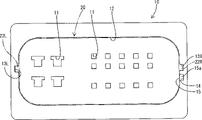
图1是第一实施例的凹形壳体的前视图;Figure 1 is a front view of a female housing of a first embodiment;
图2是凸形壳体的后视图;Figure 2 is a rear view of the male housing;
图3是前视图,示出了组合正确的凸形壳体装配在凹形壳体中的情况;Fig. 3 is a front view showing a male housing assembled correctly in a female housing;
图4是前视图,示出了组合不正确的凸形壳体装配在凹形壳体中的情况;Fig. 4 is a front view showing a situation where a male casing with an incorrect combination fits in a female casing;
图5是组合不正确的凸形壳体的后视图;Figure 5 is a rear view of an incorrectly assembled male housing;
图6是沿着图1的线vi-vi放大的横断面图;和Figure 6 is an enlarged cross-sectional view along the line vi-vi of Figure 1; and
图7是沿着图4的线vii-vii放大的横断面图。FIG. 7 is an enlarged cross-sectional view along line vii-vii of FIG. 4 .
具体实施方式Detailed ways
[第一实施例][first embodiment]
现在将参考图1到7描述本发明的优选实施例。A preferred embodiment of the present invention will now be described with reference to FIGS. 1 to 7 .
连接器包括可以正确装配在一起的凹形壳体10和凸形壳体20。另一凸形壳体(以下称为“错误壳体30”)位于凸形壳体20的附近,该错误壳体与凸形壳体20在外边缘的形状和大小上一致,但极点的数目不同于凸形壳体20。在附图中,示意地示出了凹形壳体10中空腔11的开口形状、凸形壳体20中空腔21的开口形状和错误壳体30中空腔31的开口形状。The connector comprises a
凹形壳体10具有嵌合凹部12,该嵌合凹部向它的前面敞开(即图1中呈现的面)。从前侧观察时,嵌合凹部12为具有四个弧形圆角的大致矩形形状。横截面为大致正方形的狭窄且细长的凹槽13L和13R分别形成在嵌合凹部12内边缘的左和右内侧面,并以平行于两个壳体10和20的装配方向直线延伸。两个(左和右)凹槽13L和13R中的每个从凹形壳体10的前面(嵌合凹部12的开口端)延伸到嵌合凹部12的内端面的位置附近。The
逸出凹槽部分14形成在右内侧面,并配置在凹槽13R的下方一点。该逸出凹槽部分14平行于两个壳体10和20的装配方向,逸出凹槽部分14的内端面配置在凹槽13R的内端部的前方(即,比凹槽13R的内端部更接近于凹形壳体10的前表面)。即,逸出凹槽部分14在装配方向上的长度(深度)小于凹槽13R的长度。逸出凹槽部分14的横截面形状与凹槽13R的横截面形状相同,横截面大小与凹槽13R的横截面大小相同。The
逸出凹槽部分14的内端部用作阻碍部分15,当错误壳体30(其与凹形壳体10一起构成不正确的组合)装配到凹形壳体10中时,错误壳体30的凸起32R在该装配操作期间与该阻碍部分15紧靠接合。也用作逸出凹槽部分14内端面的邻接表面15a形成在阻碍部分15上。邻接表面15a相对于两个壳体10和30的装配方向倾斜,并以这样的方向倾斜以至于当装配力作用于靠着凸起32R的邻接表面32Ra(以下描述)的邻接表面15a时,嵌合凹部12的内边缘表面和错误壳体30的外边缘表面彼此相对移动,就是说,以这样的方向以至于错误壳体30的凸起32R紧靠邻接表面15a时,凸起32R从嵌合凹部12的内表面向其外表面移动。The inner end of the
凸形壳体20可以装配在嵌合凹部12中,在装配过程期间且在完全装配的条件下,阻止凸形壳体20相对于嵌合凹部12沿垂直于装配方向的方向移动(振动)。分别相应于嵌合凹部12中左和右凹槽13L和13R的凸起22L和22R分别形成在凸形壳体20外边缘的左和右侧面。每个凸起22L和22R的形状和大小这样确定以至于凸起22L、22R可以接触相应的凹槽13L、13R的内表面而没有相对振动的平稳滑动,同样在两个壳体10和20的装配期间没有产生大的摩擦。The
像凸形壳体20一样,一对凸起32L和32R分别形成在错误壳体30外边缘的左和右侧面。错误壳体30的左凸起32L在形状、大小和位置方面与凸形壳体20的左凸起22L一致。另一方面,错误壳体30的右凸起32R配置在凸形壳体20的右凸起22R以下的位置(即,沿边缘方向偏离凸起22R的位置),就是说,在相应于嵌合凹部12中逸出凹槽部分14(阻碍部分15)的位置。错误壳体30的右凸起32R的末端面(图7中的较低表面)从错误壳体30(其与凹形壳体10相对)的前面沿装配方向向后凹进(图7中向上)。右凸起32R的末端面用作邻接表面32Ra,其倾斜的方向和角度与阻碍部分15的邻接表面15a相同。Like the
接下来,将描述该实施例的操作。Next, the operation of this embodiment will be described.
当凸形壳体20(其与凹形壳体10一起构成正确的组合)将装配到凹形壳体10中时,凸形壳体20没有阻碍地装配到嵌合凹部12中,如图3所示,两个(左和右)凸起22L和22R分别配合于相应的两个(左和右)凹槽13L和13R,以至两个壳体10和20正确地完全装配在一起。When the male housing 20 (which forms the correct combination with the female housing 10) is to be fitted into the
另一方面,当具有不同数目极点的错误壳体30装配到凹形壳体10中时,错误壳体30的左凸起32L装配到嵌合凹部12的左凹槽13L中,而错误壳体30的右凸起32R进入嵌合凹部12的逸出凹槽部分14,以至错误壳体30的一部分装配到嵌合凹部12中。当错误壳体30这样以少量装配时,形成在凸起32R末端的邻接表面32Ra与阻碍部分15的邻接表面15a紧靠接合,如图7所示,通过邻接表面32Ra与邻接表面15a的紧靠接合,阻止错误壳体30进一步的装配,以至错误壳体30不会很深地装配到正确的装配位置中。因此,确定地检测出错误壳体30部分地装配到凹形壳体10中的事实。On the other hand, when the
凸起32R的邻接表面32Ra和阻碍部分15的邻接表面15a都相对于装配方向倾斜,因此当错误壳体30将被强制装配时,由于该倾斜,嵌合凹部12的内边缘(右内侧面)向错误壳体30的外边缘(右外侧面)移动。因此,嵌合凹部12将不会立刻从错误壳体30的外表面变形,因此邻接表面15a和32Ra将彼此接合。从而,邻接表面15a和32Ra确定地保持在保持接合的状态,以至确定地阻止了两个壳体10和30相对彼此的装配进一步的进行。Both the abutment surface 32Ra of the
如上所述,在该实施例中,当壳体10和30(其构成不正确的组合)将装配在一起时,凸起32R与阻碍部分15紧靠接合,嵌合凹部12的内边缘表面由于两个邻接表面15a和32Ra的倾斜而向凸形壳体20的外边缘表面移动,因此确定地避免了当嵌合凹部12变形而向外扩展时,错误壳体30的装配通过力继续进行的情况。As described above, in this embodiment, when the
如果错误壳体的凸起和嵌合凹部的阻碍部分分别形成在错误壳体30和凹形壳体10的前面,那么在装配开始前凸起与阻碍部分紧靠接合,因此存在如下担忧,即操作者不知道组合不正确或布置不正确,得到两个壳体仅仅是互相没有对准的错误观点,并试图继续装配操作。If the protrusion of the wrong case and the obstructing portion of the fitting recess are respectively formed on the front of the
然而,在该实施例中,阻碍部分15形成在逸出凹槽部分14的内端部,该逸出凹槽部分14形成在嵌合凹部12的内边缘,凸起32R的邻接表面32Ra从错误壳体30的前面向后凹进,因此当错误壳体30的装配进行预定的行程时,该装配操作被限制,因此可以确定地检测出不正确的组合或不正确的布置。However, in this embodiment, the blocking
本发明并不限于以上参考附图所描述的实施例,例如以下的实施例落在本发明的技术范围中,而且只要不偏离本发明的主题,不同于以下实施例的其他变形也可以做出。The present invention is not limited to the embodiments described above with reference to the accompanying drawings. For example, the following embodiments fall within the technical scope of the present invention, and as long as they do not depart from the subject of the present invention, other modifications different from the following embodiments can also be made .
(1)在上述实施例中,制备多种凸形壳体和多种凹形壳体,当凹形和凸形壳体构成不正确的组合时,凸起与阻碍部分紧靠接合。然而,本发明可以应用于这种类型的连接器,其中一种凸形壳体和一种凹形壳体适合于装配在一起,当凸形壳体关于它的轴旋转或倒置(在装配方向上延伸)从而相对于凹形壳体布置不正确时,凸起可以紧靠阻碍部分,由此检测这样的错误装配。(1) In the above embodiment, various types of male housings and various types of female housings were prepared, and when the female and male housings constituted an incorrect combination, the protrusions were closely engaged with the blocking portions. However, the present invention can be applied to connectors of the type in which a male housing and a female housing are adapted to fit together when the male housing is rotated or inverted about its axis (in the fitting direction) In the event of an incorrect arrangement relative to the female housing, the protrusion can abut against the obstructing portion, thereby detecting such a wrong fit.
(2)在上述实施例中,尽管制备了两种凸形壳体和两种凹形壳体,但是本发明也可以应用于制备两种以上的凸形壳体和两种以上的凹形壳体的情况。(2) In the above embodiments, although two kinds of convex shells and two kinds of concave shells were prepared, the present invention can also be applied to prepare two or more kinds of convex shells and two or more kinds of concave shells body situation.
(3)在上述实施例中,凸起形成在凸形壳体上,而凹槽和阻碍部分形成在凹形壳体上。然而,在本发明中,凸起可以形成在凹形壳体的嵌合凹部的内边缘上,而凹槽和阻碍部分可以形成在凸形壳体的外边缘处。(3) In the above embodiments, the protrusion is formed on the male housing, and the groove and the blocking portion are formed on the female housing. However, in the present invention, the protrusion may be formed on the inner edge of the fitting recess of the female housing, and the groove and the blocking portion may be formed at the outer edge of the male housing.
(4)在上述实施例中,仅在一个区域设置了阻碍部分。然而,在本发明中,可以在多个区域分别设置这样的阻碍部分。(4) In the above-described embodiments, the blocking portion is provided only in one area. However, in the present invention, such blocking portions may be respectively provided in a plurality of regions.
(5)在上述实施例中,阻碍部分凹进,凸起从壳体的前面向后凹进。然而,在本发明中,阻碍部分和凸起中的一个或两个通常可以配置成与壳体的前面齐平。(5) In the above embodiments, the blocking portion is recessed, and the protrusion is recessed rearward from the front of the housing. However, in the present invention, one or both of the blocking portion and the protrusion may generally be arranged flush with the front of the housing.
Claims (3)
Applications Claiming Priority (2)
| Application Number | Priority Date | Filing Date | Title |
|---|---|---|---|
| JP178338/2003 | 2003-06-23 | ||
| JP2003178338A JP4093570B2 (en) | 2003-06-23 | 2003-06-23 | connector |
Publications (1)
| Publication Number | Publication Date |
|---|---|
| CN1574498A true CN1574498A (en) | 2005-02-02 |
Family
ID=33534983
Family Applications (2)
| Application Number | Title | Priority Date | Filing Date |
|---|---|---|---|
| CN200410061602.4A Pending CN1574498A (en) | 2003-06-23 | 2004-06-23 | Connector |
| CNU2004200657320U Expired - Lifetime CN2733651Y (en) | 2003-06-23 | 2004-06-23 | Connector |
Family Applications After (1)
| Application Number | Title | Priority Date | Filing Date |
|---|---|---|---|
| CNU2004200657320U Expired - Lifetime CN2733651Y (en) | 2003-06-23 | 2004-06-23 | Connector |
Country Status (3)
| Country | Link |
|---|---|
| US (1) | US6953370B2 (en) |
| JP (1) | JP4093570B2 (en) |
| CN (2) | CN1574498A (en) |
Cited By (3)
| Publication number | Priority date | Publication date | Assignee | Title |
|---|---|---|---|---|
| CN101749756A (en) * | 2008-12-19 | 2010-06-23 | 乐金电子(天津)电器有限公司 | Hot air convection type microwave oven |
| CN107732534A (en) * | 2016-08-10 | 2018-02-23 | 矢崎总业株式会社 | Connector |
| CN108879190A (en) * | 2018-06-29 | 2018-11-23 | 安徽江淮汽车集团股份有限公司 | Wire bundle plug-in connector |
Families Citing this family (8)
| Publication number | Priority date | Publication date | Assignee | Title |
|---|---|---|---|---|
| DE102006019203A1 (en) * | 2006-04-21 | 2007-10-25 | Erni-Elektro-Apparate Gmbh | Connector for connecting electronic components |
| KR101569842B1 (en) | 2009-09-30 | 2015-11-17 | 삼성전자 주식회사 | A power supply unit for a television and a television including the same |
| JP5375739B2 (en) * | 2010-05-20 | 2013-12-25 | 住友電装株式会社 | connector |
| CN102468578B (en) * | 2010-11-16 | 2016-03-16 | 泰科电子(上海)有限公司 | The method for designing of the misplug preventing device of the housing of electric connector |
| WO2012151367A2 (en) * | 2011-05-03 | 2012-11-08 | Cardioinsight Technologies, Inc. | Electrical connector plug with key to avoid contact damage |
| US8845368B1 (en) * | 2012-08-31 | 2014-09-30 | Amazon Technologies, Inc. | Electrical connectors |
| US11217941B1 (en) * | 2020-09-23 | 2022-01-04 | All Best Precision Technology Co., Ltd. | Electrical connector set, and socket and plug thereof |
| JP7626736B2 (en) * | 2022-09-26 | 2025-02-04 | 矢崎総業株式会社 | Mis-mating prevention connector |
Family Cites Families (8)
| Publication number | Priority date | Publication date | Assignee | Title |
|---|---|---|---|---|
| JP3424780B2 (en) * | 1995-06-30 | 2003-07-07 | 矢崎総業株式会社 | Connector with mating detector |
| JPH10335007A (en) * | 1997-06-02 | 1998-12-18 | Sumitomo Wiring Syst Ltd | Connector |
| US6332789B1 (en) * | 1999-05-31 | 2001-12-25 | Yazaki Corporation | Connector supporting mechanism |
| US6478632B2 (en) * | 2000-04-28 | 2002-11-12 | Sumitomo Wiring Systems, Ltd. | Shake preventing construction for a terminal fitting and a connector |
| JP3644408B2 (en) * | 2001-05-30 | 2005-04-27 | 住友電装株式会社 | connector |
| JP2003031316A (en) * | 2001-07-18 | 2003-01-31 | Jst Mfg Co Ltd | Mis-mating connector |
| JP3925165B2 (en) * | 2001-11-16 | 2007-06-06 | 住友電装株式会社 | connector |
| JP3846628B2 (en) * | 2002-02-20 | 2006-11-15 | 住友電装株式会社 | connector |
-
2003
- 2003-06-23 JP JP2003178338A patent/JP4093570B2/en not_active Expired - Lifetime
-
2004
- 2004-06-22 US US10/873,795 patent/US6953370B2/en not_active Expired - Fee Related
- 2004-06-23 CN CN200410061602.4A patent/CN1574498A/en active Pending
- 2004-06-23 CN CNU2004200657320U patent/CN2733651Y/en not_active Expired - Lifetime
Cited By (6)
| Publication number | Priority date | Publication date | Assignee | Title |
|---|---|---|---|---|
| CN101749756A (en) * | 2008-12-19 | 2010-06-23 | 乐金电子(天津)电器有限公司 | Hot air convection type microwave oven |
| CN101749756B (en) * | 2008-12-19 | 2013-11-27 | 乐金电子(天津)电器有限公司 | Hot air convection type microwave oven |
| CN107732534A (en) * | 2016-08-10 | 2018-02-23 | 矢崎总业株式会社 | Connector |
| CN107732534B (en) * | 2016-08-10 | 2019-06-28 | 矢崎总业株式会社 | Connector |
| CN108879190A (en) * | 2018-06-29 | 2018-11-23 | 安徽江淮汽车集团股份有限公司 | Wire bundle plug-in connector |
| CN108879190B (en) * | 2018-06-29 | 2019-08-06 | 安徽江淮汽车集团股份有限公司 | Wire bundle plug-in connector |
Also Published As
| Publication number | Publication date |
|---|---|
| JP4093570B2 (en) | 2008-06-04 |
| JP2005019020A (en) | 2005-01-20 |
| CN2733651Y (en) | 2005-10-12 |
| US6953370B2 (en) | 2005-10-11 |
| US20040266271A1 (en) | 2004-12-30 |
Similar Documents
| Publication | Publication Date | Title |
|---|---|---|
| CN2733651Y (en) | Connector | |
| JP3211672B2 (en) | connector | |
| CN1068977C (en) | Connector | |
| US20110070763A1 (en) | Lever-type connector | |
| JP2004171885A (en) | Connector | |
| JP2000331745A (en) | connector | |
| JP2001230021A (en) | connector | |
| US20040192119A1 (en) | Connector and a terminal fitting | |
| JP5682476B2 (en) | connector | |
| JP3804483B2 (en) | Waterproof connector | |
| JPH11214062A (en) | Double locking connector | |
| US6863551B2 (en) | Connector, set of connectors and method of connecting a connector | |
| JP2003297490A (en) | Connector | |
| JP2005005135A (en) | Connector | |
| CN114914742B (en) | Connectors | |
| JP4304490B2 (en) | Split connector | |
| JP2004014426A (en) | Connector | |
| CN1574482A (en) | A connector and a connector assembly | |
| JP2003264036A (en) | Lever type connector | |
| JPH08335473A (en) | Connector structure | |
| JP2001057269A (en) | Connector | |
| JP6879244B2 (en) | connector | |
| JPH10255891A (en) | Connector | |
| JP2002270274A (en) | Connector | |
| JP3786265B2 (en) | connector |
Legal Events
| Date | Code | Title | Description |
|---|---|---|---|
| C06 | Publication | ||
| PB01 | Publication | ||
| C10 | Entry into substantive examination | ||
| SE01 | Entry into force of request for substantive examination | ||
| C12 | Rejection of a patent application after its publication | ||
| RJ01 | Rejection of invention patent application after publication |