CN1068977C - Connector - Google Patents
Connector Download PDFInfo
- Publication number
- CN1068977C CN1068977C CN97114683A CN97114683A CN1068977C CN 1068977 C CN1068977 C CN 1068977C CN 97114683 A CN97114683 A CN 97114683A CN 97114683 A CN97114683 A CN 97114683A CN 1068977 C CN1068977 C CN 1068977C
- Authority
- CN
- China
- Prior art keywords
- mentioned
- stay
- connector
- detection piece
- connector shells
- Prior art date
- Legal status (The legal status is an assumption and is not a legal conclusion. Google has not performed a legal analysis and makes no representation as to the accuracy of the status listed.)
- Expired - Fee Related
Links
Images


Classifications
-
- H—ELECTRICITY
- H01—ELECTRIC ELEMENTS
- H01R—ELECTRICALLY-CONDUCTIVE CONNECTIONS; STRUCTURAL ASSOCIATIONS OF A PLURALITY OF MUTUALLY-INSULATED ELECTRICAL CONNECTING ELEMENTS; COUPLING DEVICES; CURRENT COLLECTORS
- H01R13/00—Details of coupling devices of the kinds covered by groups H01R12/70 or H01R24/00 - H01R33/00
- H01R13/64—Means for preventing incorrect coupling
- H01R13/641—Means for preventing incorrect coupling by indicating incorrect coupling; by indicating correct or full engagement
-
- H—ELECTRICITY
- H01—ELECTRIC ELEMENTS
- H01R—ELECTRICALLY-CONDUCTIVE CONNECTIONS; STRUCTURAL ASSOCIATIONS OF A PLURALITY OF MUTUALLY-INSULATED ELECTRICAL CONNECTING ELEMENTS; COUPLING DEVICES; CURRENT COLLECTORS
- H01R13/00—Details of coupling devices of the kinds covered by groups H01R12/70 or H01R24/00 - H01R33/00
- H01R13/62—Means for facilitating engagement or disengagement of coupling parts or for holding them in engagement
- H01R13/627—Snap or like fastening
- H01R13/6271—Latching means integral with the housing
- H01R13/6272—Latching means integral with the housing comprising a single latching arm
-
- H—ELECTRICITY
- H01—ELECTRIC ELEMENTS
- H01R—ELECTRICALLY-CONDUCTIVE CONNECTIONS; STRUCTURAL ASSOCIATIONS OF A PLURALITY OF MUTUALLY-INSULATED ELECTRICAL CONNECTING ELEMENTS; COUPLING DEVICES; CURRENT COLLECTORS
- H01R13/00—Details of coupling devices of the kinds covered by groups H01R12/70 or H01R24/00 - H01R33/00
- H01R13/62—Means for facilitating engagement or disengagement of coupling parts or for holding them in engagement
- H01R13/639—Additional means for holding or locking coupling parts together, after engagement, e.g. separate keylock, retainer strap
Abstract
A connector includes first and second connector housings which are fitted together. A seesaw or lever-type lock piece is provided in one of said connector housings and a hooking part is provided on the other connector housing for being hooked by a first downward projection of the lock piece. A detecting member is mounted for free sliding movement along the upper face of the lock piece. After a fitting operation of both housings is carried out, the detecting member is pushed forwardly. When the connector housings are in an incomplete fitted position or state, since the first downward projection is mounted on the hooking part and the lock piece is in an oblique position, the pushing of the detecting member is prevented and an incomplete fitted state is detected. When the detecting member is further pushed in, one of the housings is pushed in with the lock piece and is properly fitted. The detecting member is retained just at the position of the front end of the lock piece and the connector housings are thereby double locked.
Description
The present invention relates to a kind of connector that is provided with first and second housings.Whether it is to combine with the latch part on the stay on the housing and another housing, normally be locked together with two housings of a detection piece indication.
Just had in the past and utilize moving of stay position change to detect the connector that connector shell is local to be connected, one of them example is to be provided with the lever of buckle portion or the stay of seesaw type in the front side of the connector shell of a side, is being provided with to be used for the latch part of snap close hook portion on the connector shell of opposite side.When two housings are combined together, hook portion is installed in makes stay center on fulcrum on the latch part swingingly to push; When two housings are normally cooperated, stay revert to it the home position, be locked on the latch part by the snap close hook portion.In addition, a detection piece that is inserted in the bottom side of stay rear end is set also, when two housings were normally linked together, stay revert to its home position, and detection piece just can be inserted in the opening on the rearward end bottom side; On the other hand, when two housings are that the part is engaged in a time-out, make the stay swing on the latch part, thereby detection piece just can not insert, just can detect the incomplete connection of housing thus owing to hook portion rides over.
But above-mentioned structure has shortcoming, is under seesaw or the lever-type occasion at stay for example, is that the rear end of stay should descend if the hook portion of front end is when riding on the latch part in theory; But in fact form with resilient synthetic resin, thereby at this moment have only front end to become bending and do not make its back-end location change over downward extension owing to stay itself; Even like this can be owing to change of shape, its position changes, but this also is slightly, like this, hook portion is maintained under the position or state of incomplete cooperation, detection piece can not enter the stay rear end below, thereby can not examine then, make this usual way that insecure shortcoming be arranged.
U.S. Pat 4946395 discloses a kind of electric connector, the lock arm that an integral body is arranged on the sidewall of a connection body of this electric connector, its locking flank that is connected on the body with another pairing is meshing mutually, connects the Crossware that also has an integral body on the body at one.Simultaneously, this electric connector also has a connector position that can prevent lock arm and locking flank dislocation and determines device.Position determining means has one and the intermeshing hook-shaped lock arm of Crossware and an assay plate.Whether this connector is to detect connector in the slit between lock arm and the Crossware and be in place by the assay plate of position determining means is inserted, and after two connection bodies that detect connector are not in place, further promote position determining means, thereby two connection bodies of connector are connected fully.Simultaneously, hook-shaped lock arm meshes to prevent that two are connected the body accidental separation with Crossware.
Yet, because the Crossware of above-mentioned connector is tabular, when if two connection bodies of connector are not in place, to form a wedge-shaped crevice between lock arm and the Crossware, when in the wedge-shaped crevice that the assay plate of position determining means is inserted between lock arm and the Crossware, Crossware might produce distortion and upwards arch upward, and this moment, position determining means still can push smoothly, made people can take for connector and was in place.Therefore, still there is the insecure shortcoming of detection in the position determining means of this connector.
The present invention makes in order to solve the above problems, and its objective is provides a kind of connector that can detect incomplete mated condition reliably.
The connector of the present invention of making in order to achieve the above object, it is the stay that on any one party of the pair of connectors housing that cooperatively interacts, is provided with an energy elasticity and moves obliquely, when above-mentioned connector shell is combined together, make this stay tilt mobile by set latch part on the other side's connector shell that matches, by the stay on the home position that when two connector shells are normally cooperated, can revert to it two connector shells are locked under normal cooperation position or the state, detection piece is can move along with the inclination of stay end and move to predetermined position, when stay passed through latch part, the inclination mobile terminal of stay extended through the part of detection piece.
According to an embodiment of the invention, connector is provided with first and second connector shells, and they are to be applicable to along the cooperation direction between a plurality of incomplete cooperation positions and normal, engaged position to link together; A latch part, it is on the housing that is fixed in above-mentioned first and second connector shells.
A stay is fixed on another housing of above-mentioned first and second connector shells, and is provided with one and can moves obliquely when first and second connector shells are moved to normal, engaged position and by above-mentioned latch part and revert to the end of its home position with the above-mentioned latch part of snap close; A detection piece, it can move along above-mentioned cooperation direction, when above-mentioned first and second connector shells are in above-mentioned undesired cooperation position, see along above-mentioned cooperation direction, detection piece is that the end position with above-mentioned stay departs from, detection piece is to move and move to predetermined position along with the inclination of stay end, and during by latch part, the inclination mobile terminal of stay extends through the part of detection piece at stay; Above-mentioned detection piece is along the cooperation direction of connector shell, move to direction backwards and forward, and when detection piece extended through above-mentioned stay, above-mentioned detection piece pushed stay with predetermined power.
When above-mentioned first and second connector shells are in normal, engaged position, detection piece extends through the end of stay, and when first and second connector shells are in normal, engaged position, along cooperating direction to see that the end of stay and detection piece are unswerving each other.
Above-mentioned detection piece is provided with a pushing member, it be used for another housings of first and second connector shells never normal, engaged position be pressed to normal, engaged position, thereby first and second connector shells is dual is locked together with this.
According to another embodiment of the present invention, connector of the present invention also is provided with a member, and this is to be used for detection piece is remained on the outside of stay end.
According to another embodiment of the present invention, the end of stay is provided with first hook portion with first contact-making surface, latch part is provided with one second contact-making surface, and when first and second connectors are moved to normal, engaged position, the initial contact of first contact-making surface second contact-making surface is crossed latch part then; Second contact-making surface can tilt.
Stay is provided with a bar, and this bar is a spot wobble that centers on the opposing party's housing of first and second connector shells; Above-mentioned detection piece is provided with at least one projection, on the opposing party's housing of above-mentioned first and second connector shells, be provided with second latch part, when first and second connector shells move to normal, engaged position, above-mentioned at least one projection and the engagement of second latch part are thus with dual being locked together of above-mentioned first and second connector shells.
According to another implementation of the invention, connector is provided with: first and second connector shells, and they are to be applicable to along the cooperation direction between a plurality of incomplete cooperation positions and normal, engaged position to link together; Latch part on housing that is arranged in first and second connector shells; Stay on another housing that is arranged in first and second connector shells, this stay can the first or second connector shell medium dip move; When first and second connector shells were combined together, stay moved and crosses latch part, when connector shell is normally cooperated, by stay and latch part first and second connector shells was locked on the normal cooperation position.
An energy moves along with the inclination of stay and mobile obliquely detection piece, a protuberance that is arranged on the position that combines with the outside of the inclination mobile terminal of above-mentioned stay, when detection piece moves along with stay, above-mentioned protuberance extends through the part of above-mentioned detection piece, when first and second connector shells are in undesired cooperation position, see along above-mentioned cooperation direction, above-mentioned protuberance departs from stay, when first and second connector shells are in normal, engaged position, see that along cooperating direction the end of stay and protuberance are unswerving mutually.
When the connector housing is in incomplete cooperation, move along stay by making detection piece, detection piece extends through protuberance, detects incomplete mated condition thus.After outstanding from protuberance, when further pushing detection piece, a connector housing is pushed in another connector shell, and they normally are combined together.
When stay was crossed latch part, protuberance was in the outside of the inclination mobile terminal of stay, therefore can guarantee the detection of incomplete cooperation position.In addition, after incomplete cooperation position was detected, normal cooperation can obtain automatically by further pushing detection piece.When being pushed, detection piece can also obtain " dual locking ".
Below, by accompanying drawing, further introducing the present invention with reference to the expression various embodiments of the invention, these embodiment are nonrestrictive examples, identical label is represented identical part in these accompanying drawings.Wherein,
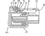
Fig. 1 is the cutaway view of connector shell state before cooperation of expression first embodiment of the invention;
Fig. 2 is the top view of the biopsy cavity marker devices of cloudy housing;
Fig. 3 is the mounting structure stereogram of expression detection piece;
Fig. 4 detects the cutaway view that housing is in incomplete mated condition;
Fig. 5 is that two housings of expression are normally cooperated and detection piece is maintained at the cutaway view of the state on the normal position:
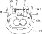
Fig. 6 is the view sub-anatomy of second embodiment of the invention;
Fig. 7 is the cutaway view of expression housing state before cooperation;
Fig. 8 is the rearview of cloudy housing;
Fig. 9 is that expression detects the cutaway view that housing is in incomplete mated condition;
Figure 10 represents that two housings are normally cooperated and the cutaway view of the maintained state of detection piece;
Figure 11 is the cloudy housing cutaway view of third embodiment of the invention;
The 12nd, the rearview of cloudy housing shown in Figure 11;
Figure 13 is the cloudy housing cutaway view of fourth embodiment of the invention;
Figure 14 is the rearview of cloudy housing shown in Figure 13.
Earlier the first embodiment of the present invention is described according to Fig. 1~Fig. 5.The connector of this first embodiment is a water proof type, and adopts the impulse force locking mode, as shown in Figure 1, is provided with the male connector housing M1 that cooperatively interacts (below abbreviate positive housing as) and female connector housing F1 (below abbreviate cloudy housing as).Sun housing M1 is by plastic and be to be connected with engineering part etc., it is made into the square tube shape with a front of freely opening and a bottom, be provided with an inner fovea part 1, setting the positive type joint that does not have expression among a plurality of figure 1 li of this inner fovea part, they are outstanding from inner fovea part 1.
Cloudy housing F1 forms with synthetic resin equally, around the front end (left side of Fig. 1) of body 2 the protective cover portion 3 that roughly is made into square tube shape is being set.Be assembled in the protective cover portion 3 above-mentioned positive housing M1 and the front end of body 2.In body 2, arranging a plurality of chambers 4 accordingly with the positive type joint of positive housing M1, negative joint is tightened up on the wire terminations that does not have expression in the drawings, and insert from behind, with its snap close, form the state that hooks with the lance shape hook 5 that is arranged on 4 li of chambers.Tightening up the water proof rubber plug in the rear end of each negative joint, thus with the inlet seal of each chamber 4.Edge is being adorned rubber ring 6 around the body 2 of the inside of protective cover portion 3, with two upper shell M1, when F1 links together, by between the perisporium that rubber ring 6 is clamped in cloudy housing F1 and positive housing M1 just with the clearance seal between two housing F1, the M1.
Between two housing M1, F1, be provided with one they are locked into the retaining mechanism of normal mated condition.Central part at the Width of the upper surface of cloudy housing F1 is being provided with stay 8, this stay 8 is made into along longitudinally and becomes elongated, and " low gate " (low gate) shape section arranged, the lower edge of the left and right sides sidewall of in the longitudinal direction substantial middle part links into an integrated entity at fulcrum 9 places and body 2, stay 8 can be resembled center on fulcrum 9 lever or the seesaw to swing.Width central part at the upper surface of protective cover portion 3 is being offered grooving 10, to admit the front end of stay 8.Front end at stay 8 forms hook portion 12, and the front contact surface 12a of hook portion 12 combines with the following latch part that forms on the upper surface of positive housing M1 13.Latch part 13 is to combine with the hook portion 12 of stay 8, and the front end of latch part 13 has the surface of a perpendicular, also has the contact surface 13a of an inclination.Like this, in the time of on cloudy housing F1 being pushed into positive housing M1, the hook portion 12 of stay 8 rides on the 13a of inclined plane, and makes stay 8 swing (referring to Fig. 4) along clockwise direction.When two housing F1, M1 were normally cooperated, hook portion 12 was crossed latch part 13, thereby stay 8 returns to original position, and by on the rear surface that hook portion 12 is latched in latch part 13 and with two housings locking (see figure 5)s.
The contact surface 12a of hook portion 12 and latch part 13,13a makes respectively under the situation of above-mentioned shape, need just can make hook portion 12 cross latch part 13 with bigger power, like this, just formed " impulse force locking ", promptly, if hook portion 12 being crossed the power of latch part 13 needed maximums sets for also bigger than the maximal friction that forms the state that is fitted to each other between male and female connector housing, then push cloudy housing F1 with impulse force, make the hook portion 12 of stay 8 cross latch part 13, and cloudy housing F1 is pushed into the normal position, thereby male and female connector is normally connected to each other two upper shell M1, F1 is locked in together to each other.
Though as above saidly under the occasion that adopts " middle power locking ", unlikelyly make two housing M1, F1 be in incomplete mated condition, but, for example cloudy housing F1 is pushed and make before stay 8 locking when the lock release direction moves, the hook portion 12 of stay 8 is ridden on the top of latch part 13 and make housing still be in incomplete mated condition (as shown in Figure 4).
In order to detect above-mentioned incomplete mated condition, a detection piece 15 is set on cloudy housing F1.This detection piece 15 is made into an independent synthetic resin sheet.Shown in Fig. 3 was detailed, detection piece 15 was made into across stay 8 and becomes " low gate " shape, forms the foot 16 of giving prominence to foreign side in left and right side and lower end.Width central part in detection piece 15 leading edges is being provided with a pressurization part 17 that preset width is arranged highlightedly, and forms the projection 18 (as described below) that snap close is used at the upper surface of the lateral border of this pressurization part 17.At the rear side with a certain distance from the detection piece 15 of this projection 18, an operating portion 19 projects upwards.
Form roughly identical with the pressurization part 17 of detection piece 15 groove 21 of width at stay 8 upper surfaces, this groove 21 extends to the rear end from the forward slightly position of the central portion of length direction, the effect of the front end genesis press section 22 of groove 21.The upper surface of the rear end of stay 8, along horizontal expansion and also slightly the highland form pressurized operation portion 23.
Cloudy housing F1 is provided with left and right sides sidewall 25, form on the inner surface of each sidewall 25 along the guide channel 26 of front and back longitudinal extension when carrying out compounding practice, respectively the slip of two foots 16 of detection piece 15 is guided.
25 front end forms high slightly roof portion 27 in the two side, and the trailing edge of this roof portion 27 just is positioned at the top of stay 8 front ends, forms at its trailing edge and can be engaged in the projection 18 of detection piece 15 and the hook portion 28 between the operating portion 19.
Outer surface in the foot 16 of detection piece 15 forms boss 30, on guide channel 26, is formed with back, the preceding bonnet lock hole 31,32 that can hold boss 30 on left and right sidewall.The bonnet lock hole 31 of rear side is used for interim the maintenance, and the bonnet lock hole 32 of front side is used for normally or keeps fully.
Also be, during installation and measuring part 15,, make stay 8 under the state of lock release direction swing by pushing above-mentioned pressurized operation portion 23, two foots 16 are inserted from the rear end of the guide channel 26 of correspondence, kept temporarily by at first boss 30 being embedded into the bonnet lock hole 31 of rear side.On this interim holding position, as shown in Figure 1, the pressurized operation portion 23 of stay 8 revert on original position, and is configured to latch on the trailing edge of detection piece 15.When detection piece 15 further being pushed, and when arriving the front end top position of stay 8 along guide channel 26, be assembled in 32 li of front side bonnet lock holes and be held by boss 30, the hook portion 28 of roof portion 27 is coupled between projection 18 and the operating portion 19.
According to above-mentioned first embodiment, earlier detection piece 15 is held on the interim holding position cloudy relatively housing F1, as shown in Figure 1.Then, in famale connector being installed to cloudy housing F1 after, cloudy housing F1 is pushed on the positive housing M1, then, boss 30 deviate from rear side bonnet lock hole 31 after, detection piece 15 is pushed forward into along guide channel 26.
In the compounding practice process of above-mentioned housing, in case being in, two housing M1, F1 do not have the normal incomplete mated condition that cooperates, just form as shown in Figure 4, the hook portion 12 of stay 8 rides on the latch part 13, swings to clockwise direction.When detection piece 15 was pushed, pressurization part 17 moved to 21 li of the grooves of the upper surface of stay 8, gives prominence to above pressurization part 22 front ends, just detects incomplete cooperation thus.
Then, when further detection piece 15 being pushed, by pushing pressurization part 22, stay 8 is pushed together with cloudy housing F1, when cloudy housing F1 is pushed into the normal position, the hook portion 12 by making it and the rear surface snap close of latch part 13 with two housing F1, M1 lockings, make stay 8 revert to its original position thus simultaneously.When detection piece 15 is pushed into precalculated position on the front end of stay 8, detection piece 15 is continued to push again, the hook portion 28 of roof portion 27 is coupled between the projection 18 and operating portion 19 of detection piece 15 as illustrated in fig. 5.And the boss 30 that makes foot 16 is coupled to 32 li of front side bonnet lock holes, and detection piece 15 is remained on stay 8 front positions, thus, can prevent floating unexpectedly of stay 8 front ends, and with connector shell " dual locking ".
Under the occasion that at the very start two housing M1, F1 is normally cooperated, guide along 26 pairs of detection pieces 15 of guide channel, and make the upper surface of its stay 8 by normally reverting to the home position, detection piece 15 can be remained on the position of stay 8 front ends as described above equally.
According to the first above-mentioned embodiment, after being coupled to cloudy housing F1 on the positive housing M1, just detection piece 15 can be pushed, and when housing is in incomplete mated condition, can detect by the outstanding of detection piece 15.And because when stay 8 rides on the latch part 13, can positively make the front end of the stay 8 that detection piece 15 setovers have changed, so can detect incomplete mated condition very reliably.
And, after detecting this incomplete mated condition, just cloudy housing F1 can be pushed into the normal position and be locked by continuing to push detection piece 15.Because detection piece 15 remains on stay 8 front positions, thereby detection piece 15 can play the effect of dual locking shell.
Below, with reference to Fig. 6~Figure 10 the second embodiment of the present invention is described.This second embodiment is provided with positive housing M2 and the cloudy housing F2 that interconnects.Sun housing M2 is made into the front and is provided with roughly square tube shape cooperating recesses 41, that the end is arranged, is disposing a plurality of a plurality of positive type joints outstanding from cooperating recesses 41 back.
Fig. 6 represents cloudy housing F2 briefly, is formed with the protective cover portion 43 that holds above-mentioned positive housing M2 on it, is adorning negative joint for 42 li at body, and they are to connect with corresponding positive type joint.
The impulse force retaining mechanism is being set between two housing M2, F2.Width central part at the upper surface of cloudy housing F2 is provided with stay 45, and this stay 45 is made into along fore-and-aft direction elongated, and forms " low gate " cross sectional shape.The lower edge of the left and right sides sidewall on the substantial middle part of length direction and body 42 link into an integrated entity and constitute fulcrum 46, and stay 45 can be swung around fulcrum 46 with lever or seesaw mode.The Width central portion of the upper surface of protective cover 43 is cut to hold the front end of stay 45.
Front end at stay 45 forms the hook portion 47 that snap close is used, and is used for latching on the following latch part that matches.Upper surface in the rear end of stay 45 forms the step 48 that upwards exceeds.
The upper surface of positive housing M2 be provided with can with the latch part 49 of hook portion 47 snap closes of above-mentioned stay 45, the contact-making surface of this latch part 49 and hook portion 47 roughly is vertical, constitute impulse force locking thus, promptly, when cloudy housing F2 being pushed to positive housing M2, overcome bigger resistance and make the hook portion 47 of stay 45 cross latch part 49, and latch on the latch part 49.After stay 45 is swung (see figure 9) along clockwise direction and ridden on the latch part 49, cloudy housing F2 is pushed into the normal position by impulse force.When normal the cooperation, because hook portion 47 is crossed latch part 49, stay 45 revert to its original position, and hook portion 47 is latched on the rear surface of latch part 49, as illustrated in fig. 10 housing is locked together thus.Can be by the rear end that pressure is applied to locking member 45 with lock release or will be in conjunction with releasing.
Even utilize above-mentioned impulse force locking type structure also can similarly be in incomplete mated condition with above-mentioned first embodiment just, the hook portion 47 of stay 45 be positioned on the upper surface of latch part 49 as illustrated in fig. 9.In order to detect this incomplete mated condition, form the detection piece 51 that a stay 45 with cloudy housing F2 separates.Detection piece 51 have than stay 45 long slightly any total length and be configured to and can be free to slide at the upper surface upper edge of stay 45 longitudinally.In more detail, at the front end of detection piece 51 detection lug 52 of deflection distortion is being set, is being provided with protuberance 53 upwards on the top of detection lug 52, the upper end, front of protuberance 53 is made into inclined-plane 53a.Form the semicircular hood 55 of gated type at the upper surface of protective cover portion 43, so that cover its front portion from the upper surface of the front end of stay 45.Extend at the upper surface of this semicircular hood 55, from the position of its trailing edge predetermined distance and form the groove 56 of opening, be provided with the latch part of using with protuberance 53 snap closes 57 in the inside of groove 56 as illustrated in fig. 10 at front end.
Inboard in the left and right sides of detection piece 51 foot 59 forms guide channel 60 along longitudinally, forms the teat 61 that can match with above-mentioned guide channel 60 on the left and right side of stay 45 rear ends with being free to slide.On the front end outer surface of two foots 59 of detection piece 51 and detection piece 51, form prominent bar 62.On the side wall inner surfaces of the left and right sides of above-mentioned semicircular hood 55, cut out the guide channel 63 that can match with above-mentioned prominent bar 62 with being free to slide.In addition, in the inside top of detection piece 51, form the mating groove 65 of the step 48 that can embed stay 45 from its trailing edge a distance.
Below, the action of second embodiment is described.Earlier detection piece 51 is contained in as illustrated in fig. 7 on the retreating position with respect to the stay 45 of cloudy housing F2.Along direction shown in the arrow of Fig. 7 cloudy housing F2 is pushed positive housing M2 then.The detection piece 51 that then will be in retreating position pushes forward.
In with above-mentioned housing engagement process,, swing towards the up time direction when then the hook portion 47 of stay 45 is on passing through latch part 49 in case two housing M2, F2 are not in incomplete mated condition by normal snap close.So detection piece 51 is pushed obliquely in the swing mode identical with stay 45, and the lower end of the protuberance 53 of detection lug 52 is contacted with the top 55a trailing edge of semicircular hood 55.Because detection lug 52 can not deflection deformation under this occasion, thereby the pushing on stay 45 of detection piece 51 be limited, and just detects the state of incomplete cooperation thus.
Then, when further detection piece 51 being pushed, by whole cloudy housing F2 being pushed with detection piece 51 pushing semicircular hood 55, when cloudy housing F2 is pushed into normal snap close position, by being latched on the rear surface of latch part 49, hook portion 47, make stay 45 revert to its home position simultaneously with two housing M2, F2 lockings.Along with the recurrence of stay 45, detection piece 51 is swing in the same direction also.The top 55a of inclined-plane 53a and semicircular hood 55 combines.Thereby when detection piece 51 is continued to push, just make detection lug 52 deflection deformation downwards and be pushed into the downside of top 55a.When detection piece 51 advances to the precalculated position, protuberance 53 is latched on the latch part 57 by making detection lug 52 recoveries and distortion.And the step 52a of the connection side of detection lug 52 contacts with the trailing edge of top 55a, and is held in the state that it moves forward and backward that limits.By detection piece 51 is remained on stay 45 directly over, just can prevent the accident swing of stay 45, thus with housing " dual locking ".
Under the situation that two housing M2 and F2 are normally cooperated from the beginning, the detection piece 51 of release is pushed into, and detection lug 52 is held by above-mentioned identical mode deflection deformation.
According to the operation principle of aforesaid second embodiment, after being coupled to cloudy housing F2 in the positive housing M2, detection piece 51 is pushed, when being under the incomplete mated condition, because detection lug 52 contacts with semicircular hood 55, make to push restrictedly, detect incomplete mated condition thus.At this moment, because the rear end of detection piece 51 is outstanding from the rear end of stay 45, thereby also can detect incomplete mated condition by observing.
Because when riding over stay 45 on the latch part 49, front end has changed its position again, so detection piece 51 pushes along stay 45, and contacts semicircular hood 55 up from the front end of stay 45.So can detect incomplete mated condition quite reliably.Because detection piece 51 is arranged on the stay 45, thereby push operation is also become carry out easily.
After detecting incomplete mated condition, push detection piece 51, by being pushed into the normal position, cloudy housing F2 is locked.Owing to can remain on the detection piece 51 that is pushed on the stay 45 that revert to original position, so can be used for detection piece 51 " dual locking " housing.
Figure 11 and Figure 12 represent third embodiment of the invention.In this embodiment, the slip guiding structural slight change on detection piece 51a and the stay.Wherein, formation and forms the guide channel 72 that holds above-mentioned guide rail 71 at the inner surface of two 59a of foot of detection piece 51a along the guide rail 71 of longitudinally on stay 45a.Remaining structure is identical with second embodiment with operation.
Figure 13 and Figure 14 represent fourth embodiment of the invention.In this embodiment, the slip guiding structural slight change on the stay 45b of detection piece 51b.Wherein, form guide rail 73 at the upper edge, left and right side of stay 45b longitudinally, and detection piece 51b two on form the guide channel 74 that holds above-mentioned guide rail 73 on the inner surface of the 59b of foot.Remaining structure is identical with second embodiment with operation.
Some embodiment that are illustrated with reference to accompanying drawing above the present invention is not limited to, for example, below said embodiment also be included in the technical scope of the present invention, and do not exceeding under the subject area situation of the present invention, can also make various changes and implement the present invention.
Among first embodiment, detection piece comprises the structure of pushing front end from the rear end of stay to, but so long as can detect incomplete mated condition, even detection piece laterally is pushed into the structure of stay front end from side, is also contained in the category of the present invention.
The present invention not only is used for traditional locking type structure, also can be used for above-mentioned " impulse force locking " formula knot Structure.
The present invention can be applicable to and be provided with arm-type stay and be connected the connection of seesaw shape stay Device, above-mentioned arm are the cantilever beam shapes that is configured to the flexible deformation.
Claims (10)
1. a connector comprises first and second connector shells, is applicable to along the cooperation direction between a plurality of incomplete cooperation positions and normal, engaged position to link together;
One latch part, it is attached on the housing in above-mentioned first and second connector shells;
One stay, it is attached on another housing in above-mentioned first and second connector shells, above-mentioned stay is provided with an end, it moves and crosses above-mentioned latch part obliquely, when first and second connector shells are moved to normal, engaged position by the home position that revert to it, so that the above-mentioned latch part of snap close;
One detection piece, it can move and when above-mentioned first and second connector shells are in above-mentioned undesired cooperation position, see along above-mentioned cooperation direction along above-mentioned cooperation direction, departs from the end position of above-mentioned stay; It is characterized in that:
Above-mentioned detection piece is to move and move to predetermined position along with the inclination of stay end, and during by latch part, the inclination mobile terminal of stay extends through the part of detection piece at stay; Above-mentioned detection piece is along the cooperation direction of connector shell, move to direction backwards and forward, and when detection piece extended through above-mentioned stay, above-mentioned detection piece pushed stay with predetermined power.
2. connector as claimed in claim 1 is characterized in that: when above-mentioned first and second connector shells were in normal, engaged position, detection piece extended through the end of above-mentioned stay; And when above-mentioned first and second connector shells are in normal, engaged position, see that along above-mentioned cooperation direction the end of above-mentioned stay and detection piece are unswerving each other.
3. connector as claimed in claim 2, it is characterized in that: above-mentioned detection piece is provided with a pushing member, its with another housing in first and second connector shells never normal, engaged position be pushed into normal, engaged position, thereby be locked together first and second connector shells are dual.
4. connector as claimed in claim 1 is characterized in that: it is provided with a member that is used for above-mentioned detection piece is remained on the outside of above-mentioned stay end.
5. connector as claimed in claim 1, it is characterized in that: the end of above-mentioned stay is provided with first hook portion with first contact-making surface, above-mentioned latch part is provided with second contact-making surface, above-mentioned first contact-making surface contacts with second contact-making surface earlier, crosses above-mentioned latch part then when above-mentioned first and second connector shells are moved to normal, engaged position.
6. connector as claimed in claim 5 is characterized in that: above-mentioned second contact-making surface tilts.
7. connector as claimed in claim 1 is characterized in that: above-mentioned stay has a bar, the fulcrum on its another housing in above-mentioned first and second connector shells and swinging.
8. connector as claimed in claim 1, it is characterized in that: above-mentioned detection piece is provided with at least one projection, second hook portion on another housing in above-mentioned first and second connector shells, when above-mentioned first and second connector shells are moved on the normal, engaged position, at least one above-mentioned projection combines with above-mentioned second hook portion, thus with dual being locked together of above-mentioned first and second connector shells.
9. a connector comprises first and second connector shells, is applicable to along the cooperation direction between a plurality of incomplete cooperation positions and normal, engaged position to link together:
One latch part, it is arranged on the housing in above-mentioned first and second connector shells,
One stay, it is arranged on another housing in above-mentioned first and second connector shells, and it can move in above-mentioned first and second connector shells obliquely; Be engaged in a time-out at above-mentioned first and second connector shells, above-mentioned stay moves and crosses above-mentioned latch part; When connector shell is normally cooperated, first and second connector shells are locked on the normal, engaged position by above-mentioned stay and latch part;
One detection piece; It is characterized in that:
Above-mentioned detection piece can Sui the inclination of stay and is moved and move obliquely, at the position that combines with the outside of the inclination mobile terminal of above-mentioned stay a protuberance is being set, when above-mentioned detection piece moves along with stay, the part of the above-mentioned detection piece of above-mentioned protuberance extend through, when above-mentioned first and second connector shells are in incomplete cooperation position, see that along above-mentioned cooperation direction above-mentioned protuberance is to depart from the end of above-mentioned stay.
10. connector as claimed in claim 9 is characterized in that: when above-mentioned first and second connector shells are in above-mentioned normal, engaged position, see along above-mentioned cooperation direction that the end of above-mentioned stay and above-mentioned protuberance are unswerving each other.
Applications Claiming Priority (3)
| Application Number | Priority Date | Filing Date | Title |
|---|---|---|---|
| JP193690/1996 | 1996-07-23 | ||
| JP19369096A JP3235478B2 (en) | 1996-07-23 | 1996-07-23 | connector |
| JP193690/96 | 1996-07-23 |
Publications (2)
| Publication Number | Publication Date |
|---|---|
| CN1171642A CN1171642A (en) | 1998-01-28 |
| CN1068977C true CN1068977C (en) | 2001-07-25 |
Family
ID=16312167
Family Applications (1)
| Application Number | Title | Priority Date | Filing Date |
|---|---|---|---|
| CN97114683A Expired - Fee Related CN1068977C (en) | 1996-07-23 | 1997-07-16 | Connector |
Country Status (5)
| Country | Link |
|---|---|
| US (1) | US6024595A (en) |
| EP (3) | EP0821441B1 (en) |
| JP (1) | JP3235478B2 (en) |
| CN (1) | CN1068977C (en) |
| DE (1) | DE69738230T2 (en) |
Families Citing this family (42)
| Publication number | Priority date | Publication date | Assignee | Title |
|---|---|---|---|---|
| JP3235478B2 (en) * | 1996-07-23 | 2001-12-04 | 住友電装株式会社 | connector |
| EP0933835B1 (en) * | 1998-02-03 | 2003-09-10 | The Whitaker Corporation | Electrical connector |
| JP2001085111A (en) * | 1999-09-10 | 2001-03-30 | Sumitomo Wiring Syst Ltd | Connector |
| JP3419715B2 (en) * | 1999-10-14 | 2003-06-23 | 株式会社オートネットワーク技術研究所 | Lock mechanism in connector |
| JP3349484B2 (en) * | 1999-11-09 | 2002-11-25 | 住友電装株式会社 | Detachment detection system for joints |
| US6273741B1 (en) * | 2000-01-14 | 2001-08-14 | Daimlerchrysler Corporation | Locking connector for antenna cable |
| JP2001291557A (en) * | 2000-04-06 | 2001-10-19 | Sumitomo Wiring Syst Ltd | Connector |
| JP3958525B2 (en) * | 2001-02-27 | 2007-08-15 | 矢崎総業株式会社 | Connector mating detection structure |
| JP3920055B2 (en) | 2001-04-12 | 2007-05-30 | 矢崎総業株式会社 | Method of assembling half-fitting prevention connector and half-fitting prevention connector |
| JP3810285B2 (en) * | 2001-06-12 | 2006-08-16 | 矢崎総業株式会社 | Half-mating prevention connector |
| CN100336271C (en) * | 2002-05-24 | 2007-09-05 | 西安富士达科技有限责任公司 | Small type push in self locking precise stationary phase connector |
| JP3903885B2 (en) * | 2002-09-02 | 2007-04-11 | 住友電装株式会社 | Connector with detection member |
| US7252556B2 (en) * | 2003-06-18 | 2007-08-07 | Fci | Electrical connector having locking claw |
| DE102004049333B4 (en) * | 2004-10-09 | 2007-03-08 | Hirschmann Automotive Gmbh | Connectors for use in vehicles |
| JP4770346B2 (en) * | 2005-09-13 | 2011-09-14 | 住友電装株式会社 | connector |
| DE102006023471B4 (en) * | 2006-05-18 | 2011-12-29 | Continental Automotive Gmbh | Device housing, in particular for a sensor for motor vehicles |
| WO2008066149A1 (en) * | 2006-12-01 | 2008-06-05 | Tyco Electronics Amp K.K. | Electric connector assembly |
| JP4968793B2 (en) * | 2006-12-01 | 2012-07-04 | タイコエレクトロニクスジャパン合同会社 | Electrical connector assembly |
| JP2008192517A (en) * | 2007-02-06 | 2008-08-21 | Tyco Electronics Amp Kk | Electric connector assembly |
| US7892014B2 (en) * | 2007-04-04 | 2011-02-22 | John Mezzalingua Associates, Inc. | Releasably engaging high definition multimedia interface plug |
| JP4911712B2 (en) * | 2007-04-10 | 2012-04-04 | タイコエレクトロニクスジャパン合同会社 | Electrical connector assembly |
| KR100858729B1 (en) * | 2007-06-27 | 2008-09-17 | 한국단자공업 주식회사 | Connector housing |
| DE102010024206B4 (en) * | 2009-07-08 | 2015-08-20 | Sumitomo Wiring Systems, Ltd. | Connector and connector with connector |
| JP2011049074A (en) * | 2009-08-27 | 2011-03-10 | Create Pro:Kk | Connector device |
| JP5511464B2 (en) * | 2010-03-26 | 2014-06-04 | 矢崎総業株式会社 | Board connection connector fitting confirmation structure |
| JP2014123466A (en) * | 2012-12-20 | 2014-07-03 | Sumitomo Wiring Syst Ltd | Connector |
| US9160095B2 (en) * | 2013-02-28 | 2015-10-13 | Yazaki North America, Inc. | Connector assembly with connector position assurance stabilizer |
| KR101491270B1 (en) * | 2013-07-05 | 2015-02-06 | 현대자동차주식회사 | High voltage connector |
| JP2015079710A (en) * | 2013-10-18 | 2015-04-23 | 住友電装株式会社 | Connector |
| US9356394B2 (en) | 2013-12-11 | 2016-05-31 | JAE Oregon, Inc. | Self-rejecting connector |
| US8968021B1 (en) | 2013-12-11 | 2015-03-03 | JAE Oregon, Inc. | Self-rejecting automotive harness connector |
| JP6347228B2 (en) * | 2015-05-11 | 2018-06-27 | 住友電装株式会社 | connector |
| EP3252880B1 (en) | 2016-06-02 | 2020-05-20 | Aptiv Technologies Limited | Electrical connector assembly with improved locking device |
| JP6850477B2 (en) * | 2017-04-24 | 2021-03-31 | 日本圧着端子製造株式会社 | Electrical connector with lock mechanism |
| US10855025B2 (en) | 2017-05-01 | 2020-12-01 | J.S.T. Corporation | Connector position assurance device, connector system and method for operating the connector system |
| US9929509B1 (en) * | 2017-06-12 | 2018-03-27 | Delphi Technologies, Inc. | Connector system with low profile connector position assurance device |
| CN107448692A (en) * | 2017-09-01 | 2017-12-08 | 特百科汽车工业(宁波)有限公司 | A kind of fluid line and the device for being provided with the fluid line |
| US10109950B1 (en) * | 2017-09-13 | 2018-10-23 | Delphi Technologies, Inc. | High vibration connector with a connector-position-assurance device |
| CN108417443B (en) * | 2018-04-09 | 2020-06-02 | 金陵科技学院 | Railway relay base locking method |
| JP2020080271A (en) * | 2018-11-14 | 2020-05-28 | 住友電装株式会社 | connector |
| JP2021005518A (en) * | 2019-06-27 | 2021-01-14 | 住友電装株式会社 | connector |
| EP3886264B1 (en) * | 2020-03-27 | 2023-11-08 | Aptiv Technologies Limited | Sealed electrical connector |
Citations (3)
| Publication number | Priority date | Publication date | Assignee | Title |
|---|---|---|---|---|
| US4946395A (en) * | 1989-07-17 | 1990-08-07 | General Motors Corporation | Electrical connector with connector position assurance device |
| EP0449239A1 (en) * | 1990-03-27 | 1991-10-02 | Yazaki Corporation | A connector engagement detecting apparatus |
| EP0717465A1 (en) * | 1994-10-10 | 1996-06-19 | Molex Incorporated | Electrical connector position assurance system |
Family Cites Families (15)
| Publication number | Priority date | Publication date | Assignee | Title |
|---|---|---|---|---|
| US4634204A (en) | 1985-12-24 | 1987-01-06 | General Motors Corporation | Electrical connector with connector position assurance/assist device |
| US4708413A (en) * | 1986-03-21 | 1987-11-24 | General Motors Corporation | Electrical connector with position assurance and assist |
| JP2537302B2 (en) * | 1990-03-01 | 1996-09-25 | 矢崎総業株式会社 | Lock check device for electrical connector |
| US5120255A (en) * | 1990-03-01 | 1992-06-09 | Yazaki Corporation | Complete locking confirming device for confirming the complete locking of an electric connector |
| JPH0466784A (en) * | 1990-07-06 | 1992-03-03 | Seiko Epson Corp | Micropump and manufacture thereof |
| JPH0472573A (en) * | 1990-07-13 | 1992-03-06 | Komatsu Ltd | Detecting device for speed of rotation |
| JP2563323Y2 (en) * | 1990-10-22 | 1998-02-18 | 矢崎総業株式会社 | connector |
| US5199902A (en) * | 1991-12-23 | 1993-04-06 | Gte Products Corporation | Connector device |
| JP2727869B2 (en) * | 1992-05-29 | 1998-03-18 | 住友電装株式会社 | Body fixing connector |
| JPH0650268U (en) * | 1992-12-07 | 1994-07-08 | 住友電装株式会社 | connector |
| US5507666A (en) * | 1993-12-28 | 1996-04-16 | Yazaki Corporation | Lock securing mechanism for connectors |
| JP2921645B2 (en) | 1994-07-12 | 1999-07-19 | 矢崎総業株式会社 | Connector mating detection structure |
| US5605471A (en) * | 1995-02-01 | 1997-02-25 | United Technologies Automotive, Inc. | Electrical connector assembly employing a connector position assurance device |
| US5720623A (en) * | 1996-06-10 | 1998-02-24 | General Motors Corporation | Position assurance electrical connector |
| JP3235478B2 (en) * | 1996-07-23 | 2001-12-04 | 住友電装株式会社 | connector |
-
1996
- 1996-07-23 JP JP19369096A patent/JP3235478B2/en not_active Expired - Fee Related
-
1997
- 1997-07-16 CN CN97114683A patent/CN1068977C/en not_active Expired - Fee Related
- 1997-07-18 EP EP97305398A patent/EP0821441B1/en not_active Expired - Lifetime
- 1997-07-18 DE DE69738230T patent/DE69738230T2/en not_active Expired - Lifetime
- 1997-07-18 EP EP07012071A patent/EP1837958A1/en not_active Withdrawn
- 1997-07-18 EP EP07012114A patent/EP1833124A3/en not_active Withdrawn
- 1997-07-23 US US08/899,141 patent/US6024595A/en not_active Expired - Lifetime
Patent Citations (3)
| Publication number | Priority date | Publication date | Assignee | Title |
|---|---|---|---|---|
| US4946395A (en) * | 1989-07-17 | 1990-08-07 | General Motors Corporation | Electrical connector with connector position assurance device |
| EP0449239A1 (en) * | 1990-03-27 | 1991-10-02 | Yazaki Corporation | A connector engagement detecting apparatus |
| EP0717465A1 (en) * | 1994-10-10 | 1996-06-19 | Molex Incorporated | Electrical connector position assurance system |
Also Published As
| Publication number | Publication date |
|---|---|
| EP1833124A2 (en) | 2007-09-12 |
| JPH1041017A (en) | 1998-02-13 |
| JP3235478B2 (en) | 2001-12-04 |
| US6024595A (en) | 2000-02-15 |
| DE69738230D1 (en) | 2007-12-06 |
| EP0821441A3 (en) | 1999-04-07 |
| EP0821441A2 (en) | 1998-01-28 |
| EP0821441B1 (en) | 2007-10-24 |
| DE69738230T2 (en) | 2008-07-31 |
| EP1837958A1 (en) | 2007-09-26 |
| CN1171642A (en) | 1998-01-28 |
| EP1833124A3 (en) | 2009-01-14 |
Similar Documents
| Publication | Publication Date | Title |
|---|---|---|
| CN1068977C (en) | Connector | |
| CN102044796B (en) | Fluidproof connector and method of assembling the same | |
| US7156684B2 (en) | Connector locking construction | |
| CN100511860C (en) | Lever type connector | |
| US5823809A (en) | Lever-type connector | |
| EP0993077B1 (en) | Half-fitting prevention connector and method of producing same | |
| CN101867118B (en) | Waterproof connector | |
| CN1773782A (en) | Connector | |
| CN102570133A (en) | Connector | |
| CN101180772B (en) | Electric connector with improved releasable locking device | |
| CN104577450A (en) | Connector | |
| JPH04163870A (en) | Connector housing lock | |
| CN1159668A (en) | Connector | |
| CN1578012A (en) | Connector | |
| CN1716708A (en) | Connector | |
| CN1477735A (en) | Waterproof connector | |
| CN102185210A (en) | Connector | |
| JP2001160457A (en) | Half-fitting preventing connector | |
| CN1265510C (en) | Electric connector subassembly and its used connector | |
| CN1756000B (en) | Terminal fitting and a connector using such a terminal fitting | |
| CN102157852A (en) | Lever connector | |
| CN1150705A (en) | Short circuit connector and retainer | |
| CN1268039C (en) | Connector | |
| CN1104753C (en) | Connector | |
| US6561833B2 (en) | Connector and a method for assembling a connector |
Legal Events
| Date | Code | Title | Description |
|---|---|---|---|
| C10 | Entry into substantive examination | ||
| SE01 | Entry into force of request for substantive examination | ||
| C06 | Publication | ||
| PB01 | Publication | ||
| C14 | Grant of patent or utility model | ||
| GR01 | Patent grant | ||
| CF01 | Termination of patent right due to non-payment of annual fee |
Granted publication date: 20010725 Termination date: 20140716 |
|
| EXPY | Termination of patent right or utility model |