连接器Connector
技术领域technical field
本发明涉及一种具有保持器的连接器。The invention relates to a connector with a retainer.
背景技术Background technique
在现有技术中,已经知道具有相对插入端子金属件的方向倾斜移动的保持器的连接器的实施例,如JP-A-8-138783中所描述的。根据该实施例,保持器安装在保持器安装孔中,设置该孔以在壳体的外表面打开,并且使保持器可在局部锁定位置和完全锁定位置之间移动,在局部锁定位置上,其抽出防止部从空腔中露出以允许插入和抽出端子金属件,在完全锁定位置上抽出防止部挤入空腔内部以被相对插入和抽出该端子金属件的方向倾斜的端子金属件锁定。In the prior art, an embodiment of a connector having a retainer that moves obliquely with respect to the direction of insertion of the terminal metal piece is known, as described in JP-A-8-138783. According to this embodiment, the retainer is installed in the retainer mounting hole, which is provided to open on the outer surface of the housing, and allows the retainer to move between a partially locked position and a fully locked position, in which, Its extraction preventing portion is exposed from the cavity to allow insertion and extraction of the terminal metal, and in the fully locked position the extraction preventing portion is squeezed into the cavity to be locked by the terminal metal that is inclined relative to the direction of insertion and extraction of the terminal metal.
发明内容Contents of the invention
然而,移动上述保持器的方向相对于插入和抽出端子金属件的方向倾斜,因此,在保持器后移的局部锁定位置上,在保持器的前边缘和保持器安装孔的前边缘之间开有预定缝隙,所关注的是外面的外物从此穿入到空腔的内部中。However, the direction of moving the above-mentioned retainer is inclined relative to the direction of inserting and withdrawing the terminal metal piece, therefore, in the partially locked position where the retainer moves backward, there is an opening between the front edge of the retainer and the front edge of the retainer mounting hole. There is a predetermined gap through which foreign objects on the outside penetrate into the interior of the cavity of concern.
在上述的连接器中,当需要执行所谓的内模具装配,例如其中壳体和保持器在相同的模具中由树脂进行模制,当模具打开时,保持器在在模具内的局部锁定位置安装到壳体上,通过从与安装保持器的方向垂直的方向滑动模具来模制该保持器安装孔是必要的,因此保持器安装孔在包括安装方向及与安装方向垂直的两侧方向的三个方向上开口。而且,当插入上级和下级上的空腔中的端子金属件旨在防止由单个保持器抽出时,该保持器安装孔在侧向上打开各个空腔,因此可能引起下面的问题。In the above-mentioned connector, when it is necessary to perform so-called in-mold assembly, such as in which the housing and the retainer are molded of resin in the same mold, when the mold is opened, the retainer is fitted in a partially locked position within the mold To the housing, it is necessary to mold the retainer mounting hole by sliding the mold from a direction perpendicular to the direction in which the retainer is mounted, so that the retainer mounting hole is in three directions including the mounting direction and both sides perpendicular to the mounting direction. opening in one direction. Also, when the terminal metal fittings inserted into the cavities on the upper and lower stages are intended to be prevented from being pulled out by a single retainer, the retainer mounting hole laterally opens the respective cavities, thus possibly causing the following problems.
即,由于移动保持器的方向相对于插入和抽出端子金属件的方向倾斜,在后移的局部锁定位置上,在保持器的前边缘和保持器安装孔的前边缘之间开有预定的缝隙。此外,该缝隙也在与保持器安装孔类似的侧向上打开,因此,插入到上空腔和下空腔中的端子金属件通过该缝隙露到外面,所关注的是由外面的外物引发短路。That is, since the direction of moving the retainer is inclined relative to the direction of inserting and withdrawing the terminal metal piece, in the partially locked position moved back, there is a predetermined gap between the front edge of the retainer and the front edge of the retainer mounting hole . In addition, the slit is also opened on the side similar to the retainer mounting hole, and therefore, the terminal metal fittings inserted into the upper and lower cavities are exposed to the outside through the slit, and there is a concern that a short circuit is caused by a foreign object on the outside. .
在前述连接器中,当需要执行所谓的内部模具装配,例如其中壳体和保持器在相同的模具中由树脂进行模制,并且模具打开时,保持器在模具内的局部锁定位置安装到壳体上,通过从与安装保持器的方向垂直的方向上滑动模具来模制该保持器安装孔是必要的。因此,从与安装方向相对的壳体中的表面到沿着安装方向互相连续的一对表面在三个方向上打开该保持器安装孔。此外,为了方便抽出防止部前进到主体部分后端的插入路径,将保持器安装孔形成到一深度,该深度用于在三个方向打开主体部分的后端上的插入路径。In the aforementioned connector, when it is necessary to perform so-called internal mold assembly, for example, in which the housing and the retainer are molded of resin in the same mold, and when the mold is opened, the retainer is fitted to the housing in a partially locked position within the mold Generally, it is necessary to mold the retainer mounting hole by sliding the mold from a direction perpendicular to the direction in which the retainer is mounted. Therefore, the retainer mounting hole is opened in three directions from the surface in the housing that is opposed to the mounting direction to a pair of surfaces that are continuous with each other along the mounting direction. Furthermore, in order to facilitate the advancement of the extraction preventing portion to the insertion path on the rear end of the main body portion, the retainer mounting hole is formed to a depth for opening the insertion path on the rear end of the main body portion in three directions.
然而,当保持器安装孔由如上所述的在三个方向上开口的模式形成时,所要注意的是导致下列问题。即,当产生一种情况,例如,设置在完全锁定位置上的保持器错误地返回到局部锁定位置一侧,或者保持器与壳体分离时,保持器安装孔的前边缘后侧上的主体部分后端的插入路径的区域在三个方向上开口。此时,当金属端子件被拉到后侧时,端子金属件在端子金属件和撞杆之间形成的间隙范围内后移,并且此时,值得注意的是主体部分的后端到达保持器安装孔前边缘的后侧区域。当外面的外物入侵保持器安装孔以到达该状态下主体部分的后端的插入路径时,前述外物接触到主体部分的后端,并且存在在宽度方向上相互邻近的端子金属件短路的可能性。However, when the retainer mounting hole is formed by the pattern opening in three directions as described above, it is to be noted that the following problems are caused. That is, when a situation arises, for example, the retainer provided at the full lock position is mistakenly returned to the partial lock position side, or the retainer is separated from the housing, the main body on the rear side of the front edge of the retainer mounting hole The region of the insertion path of the part of the rear end is open in three directions. At this time, when the metal terminal piece is pulled to the rear side, the terminal metal piece moves backward within the range of the gap formed between the terminal metal piece and the lance, and at this time, it is worth noting that the rear end of the main body part reaches the retainer The area behind the front edge of the mounting hole. When foreign matter from the outside invades the retainer mounting hole to reach the insertion path of the rear end of the main body portion in this state, the aforementioned foreign matter touches the rear end of the main body portion, and there is a possibility that the terminal metal pieces adjacent to each other in the width direction are short-circuited sex.
因此,本发明的一个目的是防止外面的物体穿过空腔。It is therefore an object of the present invention to prevent foreign objects from passing through the cavity.
本发明的另一目的是防止端子金属件短路。Another object of the present invention is to prevent short-circuiting of terminal metal pieces.
根据本发明的第一方面,提供一种连接器,包括:连接器壳体;设置在连接器壳体中并能从后侧插入端子金属件的空腔;以及在连接器壳体上形成的并在空腔的中间位置上使空腔向外侧开口的保持器安装孔,该保持器安装孔能安装保持器,其中保持器可移动地并相对于在局部锁定位置和完全锁定位置之间插入和抽出端子金属件的方向倾斜地进行安装,其中局部锁定位置允许插入和抽出端子金属件,完全锁定位置锁定端子金属件,在局部锁定位置处,缝隙在保持器的前边缘和保持器安装孔的前边缘之间打开;并且其中保持器和连接器壳体中的至少任一个具有限制部,该限制部通过突出到该缝隙的一侧限制外物穿过空腔。According to a first aspect of the present invention, there is provided a connector, comprising: a connector housing; a cavity provided in the connector housing and capable of inserting a terminal metal piece from the rear side; and a cavity formed on the connector housing And on the middle position of the cavity, the retainer installation hole that makes the cavity open to the outside, the retainer installation hole can install the retainer, wherein the retainer is movably and relatively inserted between the partial locking position and the full locking position Installed obliquely to the direction of extraction of the terminal metal, where the partially locked position allows insertion and extraction of the terminal metal, the fully locked position locks the terminal metal, and in the partially locked position, the gap is between the front edge of the retainer and the retainer mounting hole and wherein at least any one of the retainer and the connector housing has a restricting portion that restricts foreign objects from passing through the cavity by protruding to one side of the gap.
根据本发明的第二方面,提供一种连接器,包括:连接器壳体;多个空腔,设置在连接器壳体中以沿一高度方向对准,并能从后侧插入端子金属件;以及保持器安装孔,形成在连接器壳体上并在空腔的中间位置使各个空腔向外侧开口,该保持器安装孔能安装保持器,该保持器被凹口以形成为在沿与按压保持器的方向相对的表面到与该表面连续的沿所述高度方向的一对侧表面的三个方向上开口,其中保持器可移动地并相对于在局部锁定位置和完全锁定位置之间插入和抽出端子金属件的方向倾斜地进行安装,其中局部锁定位置允许插入和抽出端子金属件,完全锁定位置锁定端子金属件,在局部锁定位置处,缝隙在保持器的前边缘和保持器安装孔的前边缘之间打开;以及其中同时在保持器和连接器壳体的至少任一个上设置有突出到缝隙的一侧的突起部,并且用于当保持器移动到完全锁定位置时释放该突起部的凹陷部形成在相对侧上,从而设置与具有不同高度的各个空腔中的端子金属件对应的缝隙部分,以在前后方向上互相位移。According to a second aspect of the present invention, there is provided a connector comprising: a connector housing; a plurality of cavities provided in the connector housing to be aligned in a height direction and capable of inserting terminal metal pieces from the rear side and a retainer mounting hole formed on the connector housing and opening each cavity to the outside at the middle position of the cavity, the retainer mounting hole capable of mounting a retainer which is notched to be formed along the A surface opposite to a direction in which the retainer is pressed is open in three directions to a pair of side surfaces in the height direction continuous with the surface, wherein the retainer is movably and relatively between the partially locked position and the fully locked position. The direction of inserting and withdrawing the terminal metal piece is installed obliquely, wherein the partial locking position allows the insertion and extraction of the terminal metal piece, and the full locking position locks the terminal metal piece. In the partial locking position, the gap is between the front edge of the retainer and the retainer Open between the front edges of the mounting holes; and wherein a protrusion protruding to one side of the slit is provided on at least either of the retainer and the connector housing at the same time, and is used for releasing when the retainer moves to a fully locked position The recessed portions of the protrusions are formed on opposite sides so that slit portions corresponding to the terminal metal pieces in the respective cavities having different heights are provided to be displaced from each other in the front-rear direction.
根据本发明的第三方面,提供一种连接器,包括:连接器壳体;设置在连接器壳体中并能从后侧插入具有主体部分的端子金属件的空腔,该主体部分基本上为盒状;以及保持器安装孔,形成在连接器壳体上并能在空腔的中间位置使空腔向外侧开口,并能安装保持器;其中在空腔的内部设置有能由插入到正常深度的端子金属件锁定的撞杆,该保持器具有抽出阻止部,该抽出阻止部在保持器安装到正常安装位置时由主体部分的后端锁定,保持器在当保持器到达正常安装位置时使得保持器相对插入和抽出端子金属件的方向可倾斜移动,利用该抽出阻止部能按压插入到空腔内的深度不够的端子金属件的主体部分的后端,从而纠正到正常(regular)深度,其中保持器安装孔凹口以形成从与在连接器壳体中安装保持器的方向相对的表面到与该表面连续并沿安装保持器方向的一对表面的三个方向上的开口,并且形成到在主体部分的后端打开插入路径到三个方向的深度,以及其中抽出阻止部设置有按压突起部,当保持器安装到正常安装位置时,通过移动到从保持器安装孔的前边缘向前突出的位置,在所述空腔内,该按压突起部能按压主体部分的后端到所述位置。According to a third aspect of the present invention, there is provided a connector, comprising: a connector housing; a cavity provided in the connector housing and capable of being inserted from a rear side into a terminal metal piece having a main body portion substantially It is box-shaped; and a retainer mounting hole is formed on the connector housing and can open the cavity to the outside at the middle position of the cavity, and can install the retainer; Lever for normal depth terminal metal locking, the retainer has a pull-out stop that is locked by the rear end of the main body when the retainer is installed in the normal mounting position When the retainer can be moved obliquely relative to the direction of inserting and withdrawing the terminal metal piece, the pull-out preventing part can press the rear end of the main body part of the terminal metal piece inserted into the cavity with insufficient depth, thereby correcting to the normal (regular) depth in which the retainer mounting hole is notched to form an opening in three directions from a surface opposite to the direction in which the retainer is installed in the connector housing to a pair of surfaces continuous with the surface and along the direction in which the retainer is installed, And formed to the depth of opening the insertion path to three directions at the rear end of the main body part, and wherein the withdrawal preventing part is provided with a pressing protrusion, when the retainer is mounted to the normal mounting position, by moving to the front from the retainer mounting hole In the position where the edge protrudes forward, in the cavity, the pressing protrusion can press the rear end of the main body part to the position.
附图说明Description of drawings
本发明的目的和优点将通过参考附图详细描述其优选实施例而更明显。其中:Objects and advantages of the present invention will be more apparent by describing in detail preferred embodiments thereof with reference to the accompanying drawings. in:
图1是根据本发明第一实施例的凸壳体侧视图;Fig. 1 is a side view of a convex housing according to a first embodiment of the present invention;
图2是凸壳体的后视图;Figure 2 is a rear view of the convex housing;
图3是凸壳体的底视图;Figure 3 is a bottom view of the convex housing;
图4是保持器的侧面剖视图;Figure 4 is a side sectional view of the retainer;
图5是保持器的后视图;Figure 5 is a rear view of the retainer;
图6是保持器的底视图;Figure 6 is a bottom view of the holder;
图7是示出锁定突起和导引槽的各个外围部分的透视图;7 is a perspective view showing respective peripheral portions of a locking protrusion and a guide groove;
图8是在局部锁定位置安装有凸端子金属件和保持器的凸壳体的侧面剖视图;Figure 8 is a side sectional view of the male housing with the male terminal metal fitting and retainer installed in the partially locked position;
图9是在局部锁定位置安装有保持器的凸壳体的侧视图;Figure 9 is a side view of the male housing with the retainer installed in the partially locked position;
图10是在局部锁定位置安装有保持器的凸壳体的底视图;Figure 10 is a bottom view of the male housing with the retainer installed in the partially locked position;
图11是示出插入凸端子金属件状态的侧面剖视图;Fig. 11 is a side sectional view showing a state of inserting a male terminal metal piece;
图12是示出在完全锁定位置设置保持器的状态的侧面剖视图;Fig. 12 is a side sectional view showing a state in which the retainer is set in a fully locked position;
图13是示出在完全锁定位置设置保持器的状态的剖面图;Fig. 13 is a sectional view showing a state in which the retainer is set at a fully locked position;
图14是示出在完全锁定位置设置保持器的状态的底视图;Fig. 14 is a bottom view showing a state in which the retainer is set in a fully locked position;
图15A和15B示出模制凸壳体和保持器情况的轮廓的剖视图;Figures 15A and 15B show cross-sectional views of the outline of a molded male housing and retainer case;
图16是根据本发明第二实施例的凸壳体侧视图;Fig. 16 is a side view of a convex housing according to a second embodiment of the present invention;
图17是凸壳体的后视图;Figure 17 is a rear view of the male housing;
图18是凸壳体的底视图;Figure 18 is a bottom view of the convex housing;
图19是保持器的侧剖视图;Figure 19 is a side sectional view of the retainer;
图20是保持器的后视图;Figure 20 is a rear view of the retainer;
图21是保持器的前视图;Figure 21 is a front view of the retainer;
图22是示出锁定突起和导引槽的各个外围部分的透视图;FIG. 22 is a perspective view showing respective peripheral portions of locking protrusions and guide grooves;
图23是安装有处于局部锁定位置的保持器的端子金属件和凸壳体的侧面剖视图;Figure 23 is a side sectional view of the terminal metal fitting and male housing with the retainer installed in a partially locked position;
图24是安装有处于局部锁定位置保持器的凸壳体的部分切割侧视图;Figure 24 is a partial cutaway side view of the male housing with the retainer in a partially locked position installed;
图25是示出插入凸端子金属件到正常深度的状态的侧视图;Fig. 25 is a side view showing a state in which a male terminal metal piece is inserted to a normal depth;
图26是示出设置保持器在完全锁定位置的状态的侧面剖视图;Fig. 26 is a side sectional view showing a state in which the setting retainer is in a fully locked position;
图27是示出将保持器设置在完全锁定位置上的状态的部分切割侧视图;Fig. 27 is a partially cut side view showing a state in which the retainer is set at a fully locked position;
图28是示出在插入凸端子金属件一半时按压保持器的操作的侧面剖视图;Fig. 28 is a side sectional view showing the operation of pressing the retainer when inserting the male terminal metal piece halfway;
图29是示出插入凸端子金属件到上级侧的空腔并分离保持器的状态的侧面剖视图;29 is a side sectional view showing a state in which a male terminal metal fitting is inserted into a cavity on the upper stage side and the retainer is separated;
图30是示出拉动凸端子金属件以向后移动的状态的侧面剖视图;以及30 is a side sectional view showing a state in which the male terminal metal piece is pulled to move backward; and
图31A和31B是示出模制凸壳体和保持器的情形的轮廓的剖视图。31A and 31B are cross-sectional views showing the outline of the case where the male housing and the retainer are molded.
具体实施方式Detailed ways
现在参考附图,将详细给出本发明优选实施例的说明。Referring now to the accompanying drawings, a description will be given in detail of preferred embodiments of the present invention.
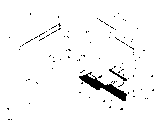
本发明的第一实施例将参考图1到图15B进行解释。根据第一实施例,举例为凸侧连接器。该连接器一般包括凸连接器壳体20(此后,简称为凸壳体20),容纳在凸壳体20内部的凸端子金属件10,以及安装到凸壳体20上的保持器40。此外,下面,凸端子金属件10插入到凸壳体20上的方向形成向前方向,抽出凸端子金属件10的方向反向形成向后方向。此外,由除图3、图6、图10、图14和图15以外的各个附图构成向上和向下方向的基准。A first embodiment of the present invention will be explained with reference to FIGS. 1 to 15B. According to a first embodiment, a male-side connector is exemplified. The connector generally includes a male connector housing 20 (hereinafter, simply referred to as the male housing 20 ), a male terminal metal piece 10 accommodated inside the male housing 20 , and a retainer 40 mounted to the male housing 20 . Further, below, the direction in which the male terminal metal piece 10 is inserted into the male housing 20 forms a forward direction, and the direction in which the male terminal metal piece 10 is withdrawn is reversed to form a rearward direction. In addition, the references of the upward and downward directions are constituted by respective drawings other than FIG. 3 , FIG. 6 , FIG. 10 , FIG. 14 , and FIG. 15 .
首先,描述凸端子金属件10。凸端子金属件10通过使冲压为预定形状的金属板弯曲形成,并包括能连接以与匹配凹金属件(未示出)接触的接头部11,基本上为盒状的主体部分12,和管状部13,其进行连接以与从如图8所示的前侧的电线W的端子产生按压接触。接头部11通过弯曲从主体部分12的前边缘延伸从而沿其长度方向紧密接触的薄板片而形成。管状部13具有在其前侧和后侧相对设置的一对填缝片,同时在前侧的该两填缝片被填塞到电线W的铁心线,在后侧的两填缝片被填塞到电线W的外壳。管状部13通过连接部19连接到主体部分12。First, the male terminal metal fitting 10 is described. The male terminal metal piece 10 is formed by bending a metal plate stamped into a predetermined shape, and includes a joint portion 11 connectable to contact with a mating female metal piece (not shown), a substantially box-shaped main body portion 12, and a tubular Part 13, which is connected so as to make press contact with the terminal of the electric wire W from the front side as shown in FIG. 8 . The joint portion 11 is formed by bending thin plate pieces extending from the front edge of the main body portion 12 so as to be in close contact along the length direction thereof. The tubular portion 13 has a pair of caulking pieces oppositely disposed on its front side and rear side, while the two caulking pieces on the front side are caulked to the core wire of the electric wire W, and the two caulking pieces on the rear side are caulked to the core wire of the electric wire W. The casing of the wire W. The tubular portion 13 is connected to the main body portion 12 by a connection portion 19 .
基本上在主体部分12的下表面(与撞杆24相对的外侧表面)的长度方向上的中心,形成用于允许装入撞杆24的凹陷部14,并且撞杆24的上部由该凹陷部的前边缘锁定。在凹陷部14的前边缘,用于锁定撞杆24的下部的锁定突起部15向外突出形成突出到下侧。形成在主体部分12的下表面的后端部处的台阶状区别部构成用于锁定保持器的锁定台阶部16。在该锁定台阶部16上,突出到与锁定突起部15的高度相同的高度并能锁定保持器40的突起部17冲压形成。在从突起部17向前的中间位置,形成进一步突出到突起部17的下侧的稳定部18,该稳定部18起到稳定凸端子金属件10的插入操作并且防止其反向插入的作用。Substantially at the center of the length direction of the lower surface (the outer side surface opposite to the lance 24 ) of the main body portion 12, a recess 14 for allowing the lance 24 to be fitted is formed, and the upper portion of the lance 24 is covered by the recess. the front edge of the lock. At the front edge of the recessed portion 14 , a locking protrusion 15 for locking the lower portion of the striker bar 24 protrudes outward so as to protrude to the lower side. A stepped distinguishing portion formed at the rear end portion of the lower surface of the main body portion 12 constitutes a locking step portion 16 for locking the retainer. On this locking step portion 16 , a protrusion portion 17 protruding to the same height as that of the locking protrusion portion 15 and capable of locking the retainer 40 is punched and formed. At an intermediate position forward from the protruding portion 17, a stabilizing portion 18 further protruding to the underside of the protruding portion 17 is formed, which functions to stabilize the insertion operation of the male terminal metal piece 10 and prevent reverse insertion thereof.
接着,描述凸壳体20。凸壳体20由合成树脂形成,如图8所示,并能构造成连接能从前侧安装匹配凹连接器的覆盖部21和能容纳凸端子金属件10的端子容纳部22。该覆盖部21基本上以向前侧开口的等高径圆柱体的形状形成,并且其内周面的上表面侧设置有锁定部(未示出),该锁定部能通过锁定设置在凹连接器上的锁定臂而将凹连接器维持在安装状态。Next, the convex housing 20 is described. The male housing 20 is formed of synthetic resin, as shown in FIG. 8 , and can be configured to connect a cover portion 21 capable of mounting a mating female connector from the front side and a terminal accommodating portion 22 capable of accommodating the male terminal metal piece 10 . The covering portion 21 is basically formed in the shape of a cylinder of equal height and diameter open to the front side, and the upper surface side of its inner peripheral surface is provided with a locking portion (not shown), which can be arranged in the female connection by locking. The locking arm on the connector keeps the female connector installed.
如图2和图8所示,端子容纳部22基本上以在其宽度方向延长的块状形状形成,在其内部设置有能从后侧插入凸端子金属件10的空腔23,并且形成该空腔23以沿前后方向穿过该凸壳体20,该空腔23以两个上下级布置以通过多个腔体在宽度方向上对准。各个空腔23的下表面设置有能弹性锁定凸端子金属件10的撞杆24。该撞杆24以悬臂形状形成以向前侧延伸,并且形成为能在上下方向(与插入和抽出凸端子金属件10的方向交叉的方向)上进行弯曲变形。此外,能插入锁定突起部15和突起部17的突起部插入槽25形成为在其整个长度上在空腔23的下表面的宽度方向的基本中心处凹入,并且能插入稳定部18的稳定部插入槽26形成为在图2中的其左侧边缘(一角部分)处凹入。该突起部插入槽25在上述撞杆24的整个长度上形成,从而减小撞杆24在插入凸端子金属件10时的弯曲量。此外,稳定部插入槽26到达从撞杆24基座端部略微向后的位置并仅向后侧敞开。此外,在上级侧,稳定部插入槽26比突起部插入槽25深,在下级侧,突起部插入槽25的深度与稳定部插入槽26的深度基本相同。As shown in FIGS. 2 and 8 , the terminal accommodating portion 22 is basically formed in a block-like shape elongated in its width direction, and a cavity 23 capable of inserting the male terminal metal piece 10 from the rear side is provided inside it, and is formed. Cavities 23 pass through the convex housing 20 in the front-rear direction, the cavities 23 being arranged in two upper and lower stages to be aligned in the width direction by the plurality of cavities. The lower surface of each cavity 23 is provided with a striker 24 capable of elastically locking the metal part 10 of the male terminal. The lance 24 is formed in a cantilever shape to extend to the front side, and is formed to be bendable in an up-down direction (a direction intersecting a direction in which the male terminal metal fitting 10 is inserted and extracted). Furthermore, a protrusion insertion groove 25 into which the locking protrusion 15 and the protrusion 17 can be inserted is formed to be recessed at a substantially center in the width direction of the lower surface of the cavity 23 over its entire length, and can be inserted into the stabilizing portion 18 . The portion insertion groove 26 is formed to be concave at its left edge (a corner portion) in FIG. 2 . This protrusion insertion groove 25 is formed over the entire length of the above-mentioned lance 24 so as to reduce the amount of bending of the lance 24 when the male terminal metal fitting 10 is inserted. Further, the stabilizer insertion groove 26 reaches a position slightly rearward from the base end of the lance 24 and is opened only to the rear side. Further, on the upper side, the stabilizing portion insertion groove 26 is deeper than the protrusion insertion groove 25 , and on the lower side, the protrusion insertion groove 25 has substantially the same depth as the stabilizing portion insertion groove 26 .
在端子容纳部22的外围表面由用于安装保持器40的保持器安装孔27打开。该保持器安装孔27在凸壳体20中的下表面(与按压保持器40的方向相对的表面)及沿按压保持器40的方向的两个侧表面的三个表面部分上形成,因此,保持器安装孔27以在三个方向上打开的模式形成。保持器安装孔27形成为深度达到从上级的空腔23的上壁23a向上的位置,并且在前后方向上分割各上下空腔23的周壁,从而使各个空腔23在中途向其外侧敞口。保持器安装孔27从上级空腔23的上壁23a向上的部分形成为不开口于侧面而开口于后侧,从而形成用于保持器主体部分41的上部41a的释放间隙28,如后所述。A holder mounting hole 27 for mounting the holder 40 is opened in the peripheral surface of the terminal accommodating portion 22 . This holder mounting hole 27 is formed on the lower surface (the surface opposite to the direction in which the holder 40 is pressed) and three surface portions of both side surfaces in the direction in which the holder 40 is pressed in the male housing 20, and therefore, The holder mounting hole 27 is formed in a pattern that opens in three directions. The retainer mounting hole 27 is formed to a depth reaching a position upward from the upper wall 23a of the upper-stage cavity 23, and divides the peripheral wall of each of the upper and lower cavities 23 in the front-rear direction, so that each cavity 23 is opened to its outer side on the way. . A portion of the retainer mounting hole 27 upward from the upper wall 23a of the upper-stage cavity 23 is formed not to open at the side but at the rear side, thereby forming a relief gap 28 for the upper portion 41a of the retainer main body portion 41 as described later. .
尽管保持器安装孔27的孔边缘的前边缘沿上下方向基本上笔直形成到约上级的空腔23的侧壁(宽度方向上的空腔23的分隔壁)的一半的深度,前侧边缘倾斜以从该处朝向前侧形成向上斜面的同时,所述前侧边缘切割所述侧壁的上半部分,此后前边缘再次在上下方向上笔直形成以切割上级空腔23的上壁和从该处开始向上的部分。因此,保持器安装孔27的前边缘的上部形成有比其下部更凹入到前侧的凹陷部38。相反,尽管保持器安装孔27的后边缘倾斜以形成朝向前侧的向上斜面到上级的空腔23的下壁23b(下级空腔23的上壁,分隔上、下空腔23的壁),但后边缘以多个预定长度而基本上水平地形成,并且此后切割下壁23b以及当侧壁再次及以后倾斜时切割上级空腔23的侧壁,笔直沿上下方向形成以切割上级空腔23的上壁23a,并且此后,再次以多个预定高度倾斜并基本上水平地形成。此外,倾斜保持器安装孔27的孔边的部分上的所有倾斜角度设置为相对凸端子金属件10的插入方向约40度(小于45度)。此外,在保持器安装孔27的后侧上的下级空腔23的下壁23c的部分形成比前侧部厚并且形成为构成于形成完全锁定位置的保持器40的高度基本上相同的高度。Although the front edge of the hole edge of the holder mounting hole 27 is formed substantially straight in the up-down direction to about half the depth of the side wall of the cavity 23 of the upper stage (the partition wall of the cavity 23 in the width direction), the front side edge is inclined. While forming an upward slope from there toward the front side, the front side edge cuts the upper half of the side wall, after which the front edge is formed straight again in the up and down direction to cut the upper wall of the upper cavity 23 and from the side wall. The part that starts upwards. Therefore, an upper portion of the front edge of the holder mounting hole 27 is formed with a recessed portion 38 that is more recessed to the front side than a lower portion thereof. On the contrary, although the rear edge of the retainer mounting hole 27 is inclined to form an upward slope toward the front side to the lower wall 23b of the cavity 23 of the upper stage (the upper wall of the cavity 23 of the lower stage, the wall separating the upper and lower cavities 23), But the rear edge is formed substantially horizontally with a plurality of predetermined lengths, and thereafter cuts the lower wall 23b and cuts the side wall of the upper cavity 23 when the side wall is inclined again and later, is formed straight in the up and down direction to cut the upper cavity 23 The upper wall 23a, and thereafter, is again inclined at a plurality of predetermined heights and formed substantially horizontally. In addition, all inclination angles on the portion of the hole side of the inclined holder mounting hole 27 are set to be about 40 degrees (less than 45 degrees) with respect to the insertion direction of the male terminal metal piece 10 . In addition, a portion of the lower wall 23c of the lower cavity 23 on the rear side of the retainer mounting hole 27 is formed thicker than the front side and formed at substantially the same height as the height of the retainer 40 forming the fully locked position.
如图1和7所示,在端子容纳部22的两侧面中,保持器安装孔27的侧面打开部分的上侧和后侧的区域形成台阶区别表面29,并比前区域更凹入。该台阶区别表面29具有以肋状沿保持器安装孔27后边缘斜度的锁定突起30。该锁定突起30主要用作当保持器40被按压以安装到凸壳体20上时稳定该按压状态。此外,在锁定突起30的外部表面,在其长度方向的中心线的分界线一侧(下侧,靠近保持器安装孔27的一侧)具有在其整个表面上的覆盖面30a,因此,安装保持器40到导引槽49中的操作能平稳地执行。此外,锁定突起30的上下两个端面分别形成具有水平表面,在上侧的端面也形成为具有延续到水平表面的垂直表面。As shown in FIGS. 1 and 7 , in both side faces of the terminal accommodating portion 22 , areas on the upper side and the rear side of the side opening portion of the holder mounting hole 27 form a step difference surface 29 and are more concave than the front area. The stepped distinguishing surface 29 has locking protrusions 30 that slope along the rear edge of the holder mounting hole 27 in a rib shape. The locking protrusion 30 is mainly used to stabilize the pressed state when the retainer 40 is pressed to be mounted on the male housing 20 . In addition, on the outer surface of the locking protrusion 30, there is a covering surface 30a on the entire surface thereof on the boundary side (the lower side, the side near the retainer mounting hole 27) of the center line in the length direction thereof, so that the mounting retaining The operation of the tool 40 into the guide groove 49 can be performed smoothly. In addition, both upper and lower end surfaces of the locking protrusion 30 are respectively formed to have horizontal surfaces, and the end surface on the upper side is also formed to have a vertical surface continuing to the horizontal surface.
此外,形成按压限制突起31以在锁定突起30的下延长线上突出。设置该按压限制突起31以从锁定突起30分开预定距离,当保持器40设置在局部锁定位置(图8到10中所示的位置)时,按压限制突起31通过由保持器40的导引槽49的下端进行锁定而限制按压,这样使得保持器40不会错误地被按压到完全锁定位置,只要按压限制突起31不被施加等于或大于预定压力的操作力。In addition, the pressing restricting protrusion 31 is formed to protrude on the lower extension line of the locking protrusion 30 . The pressing restriction protrusion 31 is provided to be separated from the locking protrusion 30 by a predetermined distance, and when the retainer 40 is set at the partial locking position (position shown in FIGS. The lower end of 49 is locked to limit the pressing, so that the retainer 40 is not pressed to the fully locked position by mistake, as long as the pressing limiting protrusion 31 is not applied with an operating force equal to or greater than a predetermined pressure.
用于在保持器40设置在完全锁定位置(如图12到图14所示的位置)时限制摇晃的摇晃限制部32突出在台阶区别表面29中的上述锁定突起30的上侧。该摇晃限制部32由沿前后方向基本水平延伸的模式形成。同时,构成朝向上侧的向上斜面的坡面32a形成在摇晃限制部32的下面的一侧上,其覆盖在摇晃限制部32的整个长度上。此外,捕捉板33突出形成在摇晃限制部32的前侧上。捕捉板33这样形成,其上边缘相对于摇晃限制部32的上边缘延续并且通过当保持器40设置在完全锁定位置时由保持器40的锁定爪52锁定,而将保持器40保持在完全锁定位置。顺便提及,捕捉板33的下面侧形成具有构成朝向上侧的向上斜面的坡面33a,从而使锁定爪52平稳骑跨于其上。此外,在保持器安装孔27的后边缘,在宽度方向上的两端的下端部设置有能将保持器40保持在如下状态的锁定凹陷部34,即通过由保持器40的锁定部48锁定该锁定凹陷部来限制保持器40,使保持器不从完全锁定位置向后侧移位。由锁定部48锁定的锁定凹陷部34由沿上下方向笔直上升的表面构成。A shake restricting portion 32 for restricting shaking when the retainer 40 is set at a fully locked position (position shown in FIGS. 12 to 14 ) protrudes above the above-mentioned locking protrusion 30 in the step distinguishing surface 29 . The sway restricting portion 32 is formed of a pattern extending substantially horizontally in the front-rear direction. Meanwhile, a slope surface 32 a constituting an upward slope toward the upper side is formed on the lower side of the sway restricting portion 32 , which covers the entire length of the sway restricting portion 32 . Furthermore, a catch plate 33 is protrudingly formed on the front side of the shake restricting portion 32 . The catch plate 33 is formed such that its upper edge continues with respect to the upper edge of the shake restricting portion 32 and holds the retainer 40 in the fully locked position by being locked by the locking pawl 52 of the retainer 40 when the retainer 40 is set at the fully locked position. Location. Incidentally, the lower face side of the catch plate 33 is formed with a slope 33a constituting an upward slope toward the upper side so that the lock pawl 52 rides smoothly thereon. In addition, at the rear edge of the retainer mounting hole 27, the lower end portions of both ends in the width direction are provided with locking recesses 34 capable of holding the retainer 40 in a state by locking the retainer 40 by the locking portion 48 of the retainer 40. The locking recess restricts the retainer 40 from being displaced rearwardly from the fully locked position. The locking recessed portion 34 locked by the locking portion 48 is constituted by a surface that rises straight in the up-down direction.
接着,描述保持器40。保持器40由类似于凹壳体20的合成树脂材料形成,如图4所示,该保持器由适于安装到保持器安装孔27中的保持器主体部分41和突出以在保持器主体部分41的宽度方向的两端部形成的一对侧板42构成。该保持器40朝向在局部锁定位置和完全锁定位置之间插入和抽出凸端子金属件10的方向可倾斜移动,随后将提及。此外,厚壁操作部43设置在两侧板42的后部。Next, the holder 40 is described. The retainer 40 is formed of a synthetic resin material similar to the female housing 20, and as shown in FIG. A pair of side plates 42 formed at both ends in the width direction of 41 are constituted. The retainer 40 is obliquely movable toward a direction of inserting and withdrawing the male terminal metal piece 10 between a partial locking position and a full locking position, which will be mentioned later. In addition, a thick-walled operation portion 43 is provided at the rear of the side panels 42 .
如图4和5所示,保持器主体部分41以具有可适应于凸壳体20的上下各个空腔23(可连接)的两上下级的格子形式形成,详细地说,这样构成,即沿宽度方向延伸的上部41a、中部41b以及下部41c由分别沿上下方向延伸的各个侧部连接。保持器主体部分41的前边缘和后边缘以基本可适应于保持器安装孔27的孔边缘的前边缘和后边缘的形式形成,上面已经提及。详细说,保持器主体部分41的前边缘从下部41c到中部41b沿上下方向笔直上升,上级侧的侧部的基本下半倾斜以构成朝向前侧的上斜面,基本所述侧部的上半和上部41a在上下方向上笔直形成。上级侧的侧部和上部41a突出到前侧的部分形成突起部44。相反,根据保持器主体部分41的后边缘,插入具有预定长度基本上形成下级的侧部的中心的水平部分的上下部以倾斜形状形成,并且该倾斜形状构成朝向前侧的向上斜面,上部41a沿上下方向笔直形成并且此后以倾斜形状形成。此外,上部41a的上表面基本上水平形成。As shown in FIGS. 4 and 5, the retainer main body portion 41 is formed in a grid form with two upper and lower stages adaptable to the upper and lower cavities 23 (connectable) of the convex housing 20, in detail, it is constructed in such a way that The upper part 41a, the middle part 41b, and the lower part 41c extended in the width direction are connected by each side part extended in the up-down direction, respectively. The front and rear edges of the holder main body portion 41 are formed in the form of front and rear edges substantially adaptable to the hole edges of the holder installation hole 27, which has been mentioned above. In detail, the front edge of the holder main body portion 41 rises straight up and down from the lower portion 41c to the middle portion 41b, the substantially lower half of the side portion on the upper stage side is inclined to constitute an upper slope toward the front side, and substantially the upper half of the side portion And the upper part 41a is formed straight in the up-down direction. The side portion on the upper stage side and the portion of the upper portion 41 a protruding to the front side form a protrusion 44 . On the contrary, according to the rear edge of the holder main body part 41, the upper and lower parts inserted into the horizontal part having a predetermined length substantially forming the center of the side part of the lower stage are formed in an inclined shape, and the inclined shape constitutes an upward slope toward the front side, the upper part 41a It is formed straight in the up and down direction and thereafter formed in an oblique shape. In addition, the upper surface of the upper portion 41a is formed substantially horizontally.
当保持器40设置在局部锁定位置时,基本上以格子形状形成的保持器主体部分41与各个空腔23连通,详细地说,在保持器主体部分41中,上部41a基本上适应于上级空腔23的上壁23a,中部41b基本上适应于上级空腔23的下壁23b,且下部41c基本上适应于下级空腔23的下壁23c,并且保持器主体部分41布置成从各个空腔13释放从而允许插入和抽出端子金属件10(图8)。在局部锁定位置,使保持器主体部分41的上部41a能由插入到上级侧空腔23中的凸端子金属件10锁定,并使中部41b能由插入到下级侧空腔23中的凸端子金属件10锁定,从而能防止保持器40从局部锁定位置向处于插入凸端子金属件状态的下侧位移。即,保持器主体部分41的上部41a和中部41b能看作构成能限制保持器40分离的抽出限制部。When the retainer 40 is set at the partial locking position, the retainer main body portion 41 formed substantially in a lattice shape communicates with the respective cavities 23, in detail, in the retainer main body portion 41, the upper portion 41a is substantially adapted to the upper-level cavity. The upper wall 23a of the cavity 23, the middle part 41b is basically adapted to the lower wall 23b of the upper cavity 23, and the lower part 41c is basically adapted to the lower wall 23c of the lower cavity 23, and the retainer main body portion 41 is arranged to be separated from each cavity. 13 is released to allow insertion and extraction of the terminal metal piece 10 (FIG. 8). In the partial locking position, the upper portion 41a of the retainer main body portion 41 is enabled to be locked by the male terminal metal piece 10 inserted into the upper-stage side cavity 23, and the middle portion 41b is enabled to be locked by the male terminal metal piece inserted into the lower-stage side cavity 23. The member 10 is locked, thereby preventing the retainer 40 from being displaced from the partially locked position to the lower side in the state where the male terminal metal member is inserted. That is, the upper portion 41 a and the middle portion 41 b of the holder main body portion 41 can be regarded as constituting a withdrawal restricting portion capable of restricting separation of the retainer 40 .
同时,当保持器40设置在完全锁定位置,保持器主体部分41的中部41b移动到上级侧的空腔23中,下部41c移动到下级侧的空腔23中,并能由凸端子金属件10的锁定台阶部16和突起部17进行锁定(图12),从而构成相对凸端子金属件10的抽出阻止部。抽出阻止部45形成为具有在局部锁定位置处适应于空腔23的稳定部插入槽26的稳定部通过槽46。此外,抽出阻止部45的后部一侧恰当地形成具有用于释放凸端子金属件10、电线W等的突起部(管状部13等)的释放凹陷部47。此外,在下部41c的宽度方向上的两端位置的后表面的下端部设置有一对锁定部48,该锁定部具有基本上三角形形状的部分,用于当保持器40到达完全锁定位置时锁定该锁定凹陷部34。此外,在完全锁定位置,在保持器主体部分41中,使突起部44释放到凹陷部38中,并且使上部41a释放到释放间隙28中。Meanwhile, when the retainer 40 is set at the fully locked position, the middle portion 41b of the retainer main body portion 41 moves into the cavity 23 on the upper-stage side, and the lower portion 41c moves into the cavity 23 on the lower-stage side, and can be moved by the male terminal metal piece 10 The locking step portion 16 and the protruding portion 17 are locked ( FIG. 12 ), thereby constituting a pull-out prevention portion for the male terminal metal fitting 10 . The withdrawal preventing portion 45 is formed with a stabilizing portion passing groove 46 adapted to the stabilizing portion inserting groove 26 of the cavity 23 at the partial locking position. Further, a release recessed portion 47 having a protrusion (tubular portion 13, etc.) for releasing the male terminal metal fitting 10, the electric wire W, etc. is appropriately formed on the rear side of the withdrawal preventing portion 45. In addition, a pair of locking portions 48 having substantially triangular-shaped portions for locking the retainer 40 when it reaches the fully locked position is provided at the lower end portions of the rear surface at both end positions in the width direction of the lower portion 41c. The recessed portion 34 is locked. Furthermore, in the fully locked position, in the retainer body portion 41 , the protrusion 44 is released into the recess 38 , and the upper portion 41 a is released into the release gap 28 .
保持器40的两侧板42以能压制以插入凸壳体20的两侧表面的间隔进行设置,并能变形以伸展。此外,以当保持器40设置在完全锁定位置时关闭保持器安装孔27侧表面的开口部分并与台阶区别表面29的预定范围相对的尺寸形成两侧板42。此外,两侧板42以与台阶区别表面29的深度基本上相同的厚度形成,并且当保持器40设置在完全锁定位置时,其表面与凸壳体20的外侧表面基本上齐平。因此,保持器40的两侧板42还用作凸壳体20的侧表面部分的外壁。Both side plates 42 of the holder 40 are provided at intervals that can be pressed to be inserted into both side surfaces of the convex housing 20 and deformed to be stretched. Further, both side plates 42 are formed in a size that closes the opening portion of the side surface of the retainer mounting hole 27 and opposes a predetermined range of the step distinguishing surface 29 when the retainer 40 is disposed at the full lock position. In addition, the side plates 42 are formed with substantially the same thickness as the depth of the step distinction surface 29, and their surfaces are substantially flush with the outer side surfaces of the convex housing 20 when the retainer 40 is disposed at the fully locked position. Therefore, the side plates 42 of the holder 40 also serve as the outer walls of the side surface portions of the convex housing 20 .
如图4所示,形成导引槽49以穿过在两侧板42的每个中的保持器主体部分41的后侧上的位置。该导引槽由沿保持器主体部分41的后边缘倾斜的斜面形成,即由与保持器安装孔27的后边缘处斜度(移动保持器40的方向)基本上相同的斜面形成。此外,导引槽49以与锁定突起30的短边侧的宽度尺寸基本上相同的槽宽形成,并且该导引槽的两端部调整为锁定突起30的两端部的形状。此外,导引槽49能通过其两前后端锁定锁定突起30和按压限制突起31,从而将保持器40保持在局部锁定位置(图9)。此外,当保持器40从局部锁定位置移动到完全锁定位置时,使按压限制突起部31压制以从导引槽49进行释放,在此期间,两侧板42变形以扩张,锁定突起30的突出量大于按压限制突起31及锁定边缘,该锁定边缘的高度足够用于继续被导引槽49锁定、甚至通过变形以扩张侧板42而被锁定的状态。因此,通过移动锁定突起30到导引槽49的下端侧,保持器40开始进入正常锁定状态(图13)。此外,具有与导引槽49基本上相同的斜度的壁减轻部50形成为穿过从两侧板42的每个中的导引槽49向下的位置。壁减轻部50的槽宽设定为比导引槽49的宽度小,并且通过适当减小两侧板42的刚性使两侧板42能容易变形以扩张。As shown in FIG. 4 , a guide groove 49 is formed to pass through a position on the rear side of the holder main body portion 41 in each of the side plates 42 . The guide groove is formed by a slope inclined along the rear edge of the holder main body portion 41 , ie, substantially the same slope as at the rear edge of the holder mounting hole 27 (direction of moving the holder 40 ). In addition, the guide groove 49 is formed with substantially the same groove width as the width dimension of the short side of the locking protrusion 30 , and both end portions of the guide groove are adjusted to the shape of both end portions of the locking protrusion 30 . In addition, the guide groove 49 can lock the locking protrusion 30 and the pressing restricting protrusion 31 by both front and rear ends thereof, thereby holding the retainer 40 at the partial locking position ( FIG. 9 ). In addition, when the retainer 40 is moved from the partial locking position to the full locking position, the pressing restricting protrusion 31 is pressed to be released from the guide groove 49, during which the both side plates 42 are deformed to expand, and the protrusion of the locking protrusion 30 The height of the locking edge is greater than that of the pressing limiting protrusion 31 and the locking edge, which is sufficiently high to continue to be locked by the guide groove 49 , even to be locked by deforming to expand the side plate 42 . Therefore, by moving the lock projection 30 to the lower end side of the guide groove 49, the retainer 40 starts to enter the normal lock state (FIG. 13). Furthermore, a wall lightening portion 50 having substantially the same slope as the guide groove 49 is formed through a position downward from the guide groove 49 in each of the side plates 42 . The groove width of the wall lightening portion 50 is set to be smaller than that of the guide groove 49, and the two side plates 42 can be easily deformed to expand by appropriately reducing the rigidity of the two side plates 42.
此外,在两侧板42的各个的内表面上的导引槽49的上侧,能安装上述的摇晃限制部32的限制凹陷部51形成以凹入,并且坡面50形成在该凹陷部上下两边。该限制凹陷部51在从长度方向上两侧板42的各个基本中心部分到达后端的范围上形成并开口于后侧。该限制凹陷部51开口于在高度方向上的上侧,其下边缘沿导引槽49的上边缘形状形成,详细说,该限制凹陷部的前部在沿前后方向基本上水平形成,其后部以构成朝向后侧的向下斜面的倾斜形状形成。此外,当保持器40设置在局部锁定位置时,摇晃限制部32的上边缘保持在与限制凹陷部51的上边缘基本对准的高度位置,并且在摇晃限制部32的下边缘和限制凹陷部51的下边缘之间保持一预定的间隙(图9)。此外,当保持器40设置在完全锁定位置时,摇晃限制部32的下边缘的坡面32a开始接触以适应于形成在限制凹陷部51的下边缘上的坡面51a,从而能限制相对于上侧的摇晃(图13)。Further, on the upper side of the guide groove 49 on the inner surface of each of the side plates 42, the restriction recessed portion 51 capable of mounting the above-mentioned shake restriction portion 32 is formed to be recessed, and the slope surface 50 is formed above and below the recessed portion. both sides. The restricting recessed portion 51 is formed over a range from each substantially central portion of the side panels 42 in the lengthwise direction to the rear end and opens to the rear side. The restriction recess 51 is opened on the upper side in the height direction, and its lower edge is formed along the shape of the upper edge of the guide groove 49. In detail, the front portion of the restriction recess 51 is formed substantially horizontally in the front-rear direction, and thereafter The portion is formed in an inclined shape constituting a downward slope toward the rear side. In addition, when the retainer 40 is set at the partial lock position, the upper edge of the sway restricting portion 32 is maintained at a height position substantially aligned with the upper edge of the restricting recess 51 , and between the lower edge of the sway restricting portion 32 and the restricting recess A predetermined gap is maintained between the lower edges of 51 (FIG. 9). In addition, when the retainer 40 is set at the fully locked position, the slope 32a of the lower edge of the sway restricting portion 32 comes into contact with the slope 51a formed on the lower edge of the restricting recess 51, thereby enabling the restriction relative to the upper sideways shaking (Figure 13).
此外,限制凹陷部51进一步延伸到前侧以扩张凹入区域,锁定爪52形成在其上边缘部分。当保持器40设置在局部锁定位置时,锁定爪52产生在基本相同高度上在凸壳体20的一侧上对锁扣板33的关联,然而,当保持器40变换到完全锁定位置,锁定爪52压制锁扣板33的坡面33a以由锁扣板33的上边缘将其锁定,从而能将保持器40保持在完全锁定位置。In addition, the restricting recessed portion 51 is further extended to the front side to expand the recessed area, and the locking claw 52 is formed at an upper edge portion thereof. When the retainer 40 is set in the partially locked position, the locking pawl 52 produces an association with the striker plate 33 on one side of the male housing 20 at substantially the same height, however, when the retainer 40 is transformed into the fully locked position, the locking The pawl 52 presses the slope 33a of the striker plate 33 to be locked by the upper edge of the striker plate 33, so that the retainer 40 can be held in the fully locked position.
同时,移动保持器40的方向定向为相对插入和抽出凸端子金属件10的方向倾斜的方向,并且因此,在从完全锁定位置后移的局部锁定位置,如图8所示,向下开口的缝隙35和向两侧开口的缝隙36在保持器40的前边缘和保持器安装孔27的前边缘之间形成。At the same time, the direction of moving the retainer 40 is oriented in a direction oblique to the direction of inserting and withdrawing the male terminal metal piece 10, and therefore, in the partially locked position moved back from the fully locked position, as shown in FIG. A slit 35 and a slit 36 open to both sides are formed between the front edge of the holder 40 and the front edge of the holder mounting hole 27 .
此外,保持器40具有能通过突出到开口于下侧的缝隙35的一侧而限制外物穿过进入到空腔23的限制部53。该限制部53设置成突出到保持器主体部分41的下部41c的下端部前表面的前侧,并且其突出大小设定为比缝隙35在前后方向上的长度大。限制部53的宽度尺寸设置为与保持器主体部分41的基本上相同(比凸壳体20的端子容纳部22的小),在宽度方向上的其两侧形成为具有由切割拐角部分得到的坡面。使该限制部53能覆盖开口于沿宽度方向的下侧的缝隙35,并设置该限制部以打开距离端子容纳部22的下表面的预定间隔(移动保持器40的高度量)。此外,关于打开到侧部的缝隙36,由于互相平行形成的保持器安装孔27的前边缘和保持器40的前边缘上部以从其下部突出到前侧的模式构造,所以上侧部36a(对应于上级的空腔23的上半部的区域)和下侧部36b(对应于下级空腔23的整个区域和上级空腔23的下半部的区域)在前后方向上位移。换句话说,缝隙36由保持器主体部分41的突起部44分割为上侧部36a和下侧部36b,并且这两部件设置成在前后方向上位移。In addition, the holder 40 has a restricting portion 53 capable of restricting passage of foreign objects into the cavity 23 by protruding to one side of the slit 35 opened on the lower side. The restriction portion 53 is provided to protrude to the front side of the lower end front surface of the lower portion 41 c of the holder main body portion 41 , and its protrusion size is set to be larger than the length of the slit 35 in the front-rear direction. The width dimension of the restriction portion 53 is set to be substantially the same as that of the holder main body portion 41 (smaller than that of the terminal accommodating portion 22 of the male housing 20), and both sides thereof in the width direction are formed with corner portions obtained by cutting. slope. The restricting portion 53 is made to cover the slit 35 opened to the lower side in the width direction, and is provided to open a predetermined interval (the height amount of the moving holder 40 ) from the lower surface of the terminal accommodating portion 22 . Further, regarding the slit 36 opened to the side, since the front edge of the retainer mounting hole 27 and the upper portion of the front edge of the retainer 40 formed in parallel to each other are configured in a pattern protruding from the lower portion thereof to the front side, the upper side portion 36a ( The region corresponding to the upper half of the cavity 23 of the upper stage) and the lower side portion 36b (the region corresponding to the entire region of the lower cavity 23 and the region of the lower half of the upper cavity 23 ) are displaced in the front-rear direction. In other words, the slit 36 is divided into an upper side portion 36 a and a lower side portion 36 b by the protrusion 44 of the holder main body portion 41 , and these two parts are arranged to be displaced in the front-rear direction.
当保持器40的前边缘设置有突出到开口于侧面的缝隙36的一侧的突起部44时,保持器安装孔27上与突起部44相对的前边缘和按压保持器40的方向(倾斜前方)形成以凹入用于当保持器40移动到完全锁定位置时释放突起部44的凹陷部38。因此,打开到该侧的缝隙36设置有形成在突起部44和凹陷部38之间的上侧部36a和在前后方向上互相位移的下侧部36b。When the front edge of the holder 40 is provided with the protrusion 44 protruding to one side of the slit 36 opening on the side, the front edge of the holder mounting hole 27 opposite to the protrusion 44 and the direction of pressing the holder 40 (inclined forward ) is formed to recess the recessed portion 38 for releasing the protrusion 44 when the retainer 40 is moved to the fully locked position. Therefore, the slit 36 opened to this side is provided with an upper side portion 36 a formed between the protrusion portion 44 and the recessed portion 38 and a lower side portion 36 b displaced from each other in the front-rear direction.
详细的说,突起部44形成在从从上级空腔23的上壁23a略微向上的位置到局部锁定位置上的上级空腔23的下端位置的区域内,其下表面由倾斜表面形成,该倾斜表面构成直到上级空腔23基本上中心位置的前侧的向上斜面。该凹陷部38在从上级空腔23的基本中心位置到上壁23a的更向上的位置的区域内形成,并且其下表面由倾斜表面形成,该倾斜表面基本上构成沿着突起部44的倾斜表面的直线形状。突出该突起部44到前侧的长度设定为比当保持器40从局部锁定位置移动到完全锁定位置时向前侧移动该保持器40的距离略小。因此,在局部锁定位置,突起部44设置在凹陷部38的略前侧(在后方向上)。In detail, the protrusion 44 is formed in a region from a position slightly upward from the upper wall 23a of the upper cavity 23 to a lower end position of the upper cavity 23 at the partially locked position, and the lower surface thereof is formed by an inclined surface, which is inclined. The surface forms an upward slope up to the front side of the upper cavity 23 at an essentially central position. This recessed portion 38 is formed in a region from the substantially central position of the upper cavity 23 to a more upward position of the upper wall 23a, and its lower surface is formed by an inclined surface substantially constituting an inclination along the protruding portion 44. The rectilinear shape of the surface. The length protruding the protrusion 44 to the front side is set to be slightly smaller than the distance to move the retainer 40 to the front side when the retainer 40 moves from the partial lock position to the full lock position. Therefore, in the partial lock position, the protrusion 44 is disposed slightly on the front side (in the rear direction) of the recess 38 .
如图11所示,形成在突起部44和凹陷部38之间的缝隙的上侧部36a设置在侧方向上将插入到上级空腔23中的凸端子金属件10的主体部分12的部分(后端的上部)暴露到外部的位置上。相反,缝隙36的下侧部36b设置在侧方向上将插入到下级空腔23中的凸端子金属件10的主体部分12的部分(后半部)暴露在外部的位置上。此外,尽管缝隙36的下侧部36b在侧向上打开上级空腔23的一部分,但由于该位置是在凸端子金属件10的锁定台阶部16的后侧和连接部19的下侧上的部分,因此上级的凸端子金属件10并不能暴露于该部分。这样,尽管上侧部36a和下侧部36b分别暴露出插入到具有不同高度的空腔23中的凸端子金属件10,但该暴露部分在上下级之间的前后方向上位移。此外,缝隙36的上侧部36a和下侧部36b由于上述突起部44的长度尺寸的关系互相连接,并且随着接近边界位置,前后方向上的开口区域逐渐变窄。As shown in FIG. 11 , the upper side portion 36 a of the gap formed between the protrusion portion 44 and the recess portion 38 is provided in the side direction at the portion of the body portion 12 of the male terminal metal fitting 10 to be inserted into the upper-stage cavity 23 ( The upper part of the rear end) is exposed to the outside. In contrast, the lower side portion 36b of the slit 36 is provided at a position where a portion (rear half) of the main body portion 12 of the male terminal metal fitting 10 inserted into the lower cavity 23 is exposed to the outside in the side direction. Furthermore, although the lower side portion 36b of the slit 36 laterally opens a part of the upper cavity 23, since this position is the portion on the rear side of the locking step portion 16 of the male terminal metal fitting 10 and the lower side of the connection portion 19 , so the upper-stage male terminal metal piece 10 cannot be exposed to this part. Thus, although the upper side portion 36a and the lower side portion 36b respectively expose the male terminal metal fitting 10 inserted into the cavity 23 having different heights, the exposed portion is displaced in the front-rear direction between the upper and lower stages. In addition, the upper side portion 36a and the lower side portion 36b of the slit 36 are connected to each other due to the above-mentioned length dimension of the protrusion portion 44, and the opening area in the front-rear direction gradually narrows as the boundary position is approached.
此外,保持器40具有能通过突出于向下打开的缝隙35一侧而限制外物穿过进入空腔的内部的限制部53。通过从保持器主体部分41的下部41c的下端部的前表面向前侧突出而设置该限制部53,并且其突出尺寸设定为比缝隙35在前后方向上的长度大。根据该限制部53,宽度尺寸设定为与保持器主体部分41的基本相同(比凸壳体20的端子容纳部22的小),其宽度方向上的两侧部分形成具有通过切割其拐角部分得到的坡面。使该限制部53能覆盖沿其基本上整个区域的宽度方向向下开口的缝隙35,并且通过从端子容纳部22的下表面打开预定间隔(从端子容纳部22的下表面移动该保持器40的高度量)设置该限制部。In addition, the holder 40 has a restricting portion 53 capable of restricting passage of foreign objects into the interior of the cavity by protruding beyond the side of the slit 35 opened downward. The restricting portion 53 is provided by protruding to the front side from the front surface of the lower end portion of the lower portion 41 c of the holder main body portion 41 , and its protruding dimension is set to be larger than the length of the slit 35 in the front-rear direction. According to this restricting portion 53, the width dimension is set to be substantially the same as that of the holder main body portion 41 (smaller than that of the terminal accommodating portion 22 of the male housing 20), and both side portions in the width direction thereof are formed with corner portions by cutting. obtained slope. The restricting portion 53 is made to cover the slit 35 opening downward in the width direction of substantially the entire area thereof, and by opening a predetermined interval from the lower surface of the terminal accommodating portion 22 (moving the holder 40 from the lower surface of the terminal accommodating portion 22 The height amount) set the limit part.
当保持器40安装到完全锁定位置时,使限制部53的上表面能与端子容纳部22的下表面进行接触。此时,限制部53的前侧设置有设置在端子容纳部22处的捕捉阻止部37以互相接近以在限制部和捕捉阻止部之间打开一个微小的缝隙(到比电线的直径足够窄的程度),从而防止外部电线等由限制部53碰到。该捕捉阻止部37突出到从保持器安装孔27向前的端子容纳部22的下表面位置处的下侧上,使其突出尺寸小于限制部53的厚度尺寸。捕捉阻止部37的宽度尺寸设定为比端子容纳部22的整个宽度上的尺寸大,即比限制部53大。When the retainer 40 is mounted to the fully locked position, the upper surface of the restricting portion 53 is brought into contact with the lower surface of the terminal accommodating portion 22 . At this time, the front side of the restricting portion 53 is provided with the catch preventing portion 37 provided at the terminal accommodating portion 22 to approach each other to open a slight gap (to a diameter sufficiently narrower than the diameter of the electric wire) between the restricting portion and the catching preventing portion. extent), thereby preventing external wires and the like from being hit by the restricting portion 53. The catch preventing portion 37 protrudes onto the lower side at the position of the lower surface of the terminal accommodating portion 22 forward from the holder mounting hole 27 such that the protruding dimension thereof is smaller than the thickness dimension of the restricting portion 53 . The width dimension of the catch preventing portion 37 is set to be larger than the entire width dimension of the terminal accommodating portion 22 , that is, larger than the restricting portion 53 .
第一实施例由上述结构形成,其操作将随后进行解释。首先,将解释模制凸壳体20和保持器40的方法。总的来说,凸壳体20和保持器40由树脂在相同模制模具的内部进行模制,保持器40在该模具内部的局部锁定位置上集成到凸壳体20上。The first embodiment is formed by the above structure, and its operation will be explained later. First, a method of molding the male housing 20 and the holder 40 will be explained. In general, the male housing 20 and the retainer 40 are molded from resin inside the same molding mould, the retainer 40 being integrated to the male housing 20 in a partially locked position inside this mould.
详细的说,如图15A和15B所示,整个凸壳体20通过沿空腔23的长度方向(所示的上下方向)打开和关闭的一对模具60,61进行模制,保持器安装孔27由沿垂直于上述方向并垂直于安装保持器40的方向(垂直于附图的纸面的方向)的方向向前和向后移动的滑动模具62,即移入凸壳体20的侧面或从该侧面后移滑动模具62来进行模制。此外,保持器40同样在与模制凸壳体20的模具60,61相同的模具中进行保持器安装孔模制的部分演示的右侧的位置上进行模制。此外,在打开模具后,当保持器40通过推动销63推到保持器安装孔27上时,保持器40能安装到局部锁定位置。即,实现内模集成(内模装配)。In detail, as shown in FIGS. 15A and 15B, the entire male housing 20 is molded by a pair of molds 60, 61 that are opened and closed along the length direction of the cavity 23 (up-and-down direction as shown), and the retainer mounting holes 27 is moved forward and backward by the sliding die 62 in the direction perpendicular to the above-mentioned direction and perpendicular to the direction of mounting the holder 40 (direction perpendicular to the paper of the drawings), that is, into the side of the convex housing 20 or from the The side slides mold 62 back for molding. In addition, the retainer 40 is also molded in the same mold as the mold 60 , 61 for molding the male housing 20 at the position on the right side of the partial demonstration of the retainer mounting hole molding. In addition, when the retainer 40 is pushed onto the retainer mounting hole 27 by the push pin 63 after the mold is opened, the retainer 40 can be mounted to the partially locked position. That is, internal mold integration (internal mold assembly) is realized.
当保持器40以这种方式在局部锁定位置安装到凸壳体时,如图8所示,凸端子金属件10从后侧插入到各个空腔23中。那么,插入凸端子金属件10的动作通过将锁定突起部15、稳定部18、和突起部17相应地连续地插入到突起部插入槽25、稳定部插入槽26及稳定部通过槽46中而光滑地被导引。当凸端子金属件10插入到预定深度时,撞杆24受锁定部15压迫而暂时变形以弯曲到下侧。此外,当凸端子金属件10到达正常深度时,如图11所示,锁定突起部15压制撞杆24,该撞杆24弹性恢复进入到凹陷部14中以由凹陷部14的前边缘和锁定突起部15的后端面进行锁定。When the retainer 40 is mounted to the male housing in the partially locked position in this way, as shown in FIG. 8 , the male terminal metal piece 10 is inserted into each cavity 23 from the rear side. Then, the action of inserting the male terminal metal piece 10 is achieved by inserting the locking protrusion 15, the stabilizing portion 18, and the protruding portion 17 into the protrusion insertion groove 25, the stabilizing portion insertion groove 26, and the stabilizing portion passing groove 46 respectively and continuously. Guided smoothly. When the male terminal metal fitting 10 is inserted to a predetermined depth, the lance 24 is pressed by the locking portion 15 to temporarily deform to bend to the lower side. In addition, when the male terminal metal piece 10 reaches the normal depth, as shown in FIG. The rear end surface of the protrusion 15 is locked.
当所有的凸端子金属件10完成插入时,执行将保持器40从局部锁定位置移动到完全锁定位置的操作。当在倾斜的上前方向按压保持器时,导引槽49的下端部的外围变形以压制按压限制部31从而从导引槽49移出,使保持器40动作以通过将在倾斜上方被按压的锁定突起30和导引槽49安装到一起而进行导引。此外,当保持器40达到完全锁定位置时,如图12所示,各个抽出阻止部45进入到各个空腔23中以由锁定台阶部16和凸端子金属件10的突起部17的后端面进行锁定,从而双重防止凸端子金属件10被抽出。当保持器达到完全锁定位置时,如图14所示,设置该限制部53最接近捕捉阻止部37的中后侧。由于具有该捕捉阻止部37,防止外部电线等由限制部53捕获,从而防止出现由所捕获的电线拖动保持器40而使之移动到局部锁定位置一侧的情况。When all the male terminal metal pieces 10 are completely inserted, the operation of moving the retainer 40 from the partially locked position to the fully locked position is performed. When the holder is pressed in the oblique upward and forward direction, the periphery of the lower end portion of the guide groove 49 is deformed to press the pressing restricting portion 31 to move out from the guide groove 49, so that the holder 40 moves to pass the The locking protrusion 30 and the guide groove 49 are fitted together for guidance. Furthermore, when the retainer 40 reaches the fully locked position, as shown in FIG. locked, thereby doubly preventing the male terminal metal piece 10 from being pulled out. When the retainer reaches the fully locked position, as shown in FIG. 14 , this restricting portion 53 is provided closest to the middle rear side of the catch preventing portion 37 . With this catching preventing portion 37 , external electric wires and the like are prevented from being caught by the restricting portion 53 , thereby preventing the retainer 40 from being dragged by the caught electric wires to move to the partial locking position side.
在完全锁定位置,如图13所示,锁定突起30由导引槽49的下端锁定,并且按压限制突起31设置成转移到动作部43的后侧。此外,这时除了通过锁扣板33的上边缘压制锁扣板33的坡面33a而锁定锁定爪52以外,锁定部48进入到凹陷部34中以利用锁定凹陷部34的前表面锁定其后表面,从而双重地将保持器40保持在完全锁定位置(图12)。此外,通过由限制凹陷部51的下边缘锁定摇晃限制部32的下边缘,也限制了保持器40向上侧的摇晃。此外,在完全锁定位置,保持器主体部分41的前边缘接触到保持器安装孔27的前边缘,该保持器安装孔包括突起部44和凹陷部38,两部件基本闭合而没有缝隙,因此,能防止灰尘和尘土等穿过进入到空腔23的内部。当凸连接器已经完成如上所述的集成时,将未示出的匹配的凹连接器连接以安装到罩盖部21的内部。In the fully locked position, as shown in FIG. 13 , the locking protrusion 30 is locked by the lower end of the guide groove 49 , and the pressing restricting protrusion 31 is provided to be shifted to the rear side of the action portion 43 . In addition, at this time, in addition to locking the locking pawl 52 by pressing the slope surface 33a of the locking plate 33 by the upper edge of the locking plate 33, the locking portion 48 enters into the recessed portion 34 to lock thereafter with the front surface of the locking recessed portion 34. surface, thereby doubly retaining the retainer 40 in the fully locked position (FIG. 12). Furthermore, by locking the lower edge of the shake restricting portion 32 by the lower edge of the restricting recessed portion 51 , shaking of the holder 40 to the upper side is also restricted. In addition, in the fully locked position, the front edge of the retainer main body portion 41 contacts the front edge of the retainer mounting hole 27, which includes the protrusion 44 and the recess 38, and the two parts are substantially closed without gaps, therefore, Dust and dust can be prevented from penetrating into the cavity 23 . When the male connector has been integrated as described above, a mating female connector not shown is connected to be installed inside the cover portion 21 .
当将两连接器安装到一起时,值得注意的是由于某些原因而意外的将插入连接器40返回到局部锁定位置,那么,如图11所示,缝隙35,36在保持器40的前边缘和保持器安装孔27的前边缘之间打开。然而,根据开口于侧面的缝隙36,上侧部36a和下侧部36b在前后方向上位移,因此,只有上级侧的凸端子金属件10的主体部分12的一部分暴露到上侧部36a,连接部19的基本整个区域由突起部44进行覆盖,连接部19几乎不露出。相反,仅仅下级侧的凸端子金属件10的连接部19的一部分暴露到下侧部36b,主体部分12的整个区域由空腔23的外围壁覆盖,不露出。即,上级侧的凸端子金属件10和下级侧的凸端子金属件10暴露到侧面的部分在前后方向上互相转换,另外,当上侧部36a和下侧部36b互相接近时缝隙36形成为逐渐变窄,因此,使外部工具等难于同时与上下凸端子金属件10进行接触,因此,防止了上下方向上对准的凸端子金属件10短路的情况。此外,在局部锁定位置,保持器主体部分41的上部41a和中部41b由凸端子金属件10在空腔23内部进行锁定,因此,防止了将保持器40从主壳体20分离的情况。When installing the two connectors together, it is worth noting that due to some reasons, the plug-in connector 40 is accidentally returned to the partial locking position. Then, as shown in FIG. There is an opening between the edge and the front edge of the retainer mounting hole 27. However, according to the slit 36 opened on the side, the upper side portion 36a and the lower side portion 36b are displaced in the front-rear direction, therefore, only a part of the main body portion 12 of the male terminal metal fitting 10 on the upper stage side is exposed to the upper side portion 36a, and the connection The substantially entire area of the portion 19 is covered by the protruding portion 44, and the connection portion 19 is hardly exposed. In contrast, only a part of the connecting portion 19 of the male terminal metal fitting 10 on the lower side is exposed to the lower side portion 36b, and the entire area of the main body portion 12 is covered by the peripheral wall of the cavity 23 without being exposed. That is, the male terminal metal fitting 10 on the upper stage side and the portion exposed to the side of the male terminal metal fitting 10 on the lower stage side are mutually switched in the front-rear direction, and the slit 36 is formed when the upper side portion 36a and the lower side portion 36b approach each other. The taper narrows, thus making it difficult for an external tool or the like to come into contact with the upper and lower male terminal metal fittings 10 at the same time, thus preventing short-circuiting of the male terminal metal fittings 10 aligned in the vertical direction. Further, in the partially locked position, the upper portion 41a and the middle portion 41b of the retainer main body portion 41 are locked inside the cavity 23 by the male terminal metal fitting 10, thus preventing the retainer 40 from being separated from the main housing 20.
此外,向下开口的缝隙35由限制部53在其基本总宽度上进行覆盖,因此,例如,防止电线或工具穿入空腔23,因此,防止了损坏凸端子金属件10的情况或在宽度方向上对准的凸端子金属件10短路的情况。此外,甚至例如在插入凸端子金属件10之前阶段和在安装到局部锁定位置的状态下将保持器40运送到集成点的过程中,由限制部53防止了外物穿过空腔23。In addition, the downwardly opening slit 35 is covered by the restricting portion 53 over its substantially entire width, thus, for example, preventing wires or tools from penetrating into the cavity 23, thus preventing damage to the male terminal metal piece 10 or in the width. The case where the male terminal metal pieces 10 aligned in the direction are short-circuited. Furthermore, foreign objects are prevented from passing through the cavity 23 by the restricting portion 53 even, for example, at a stage before insertion of the male terminal metal fitting 10 and during transport of the retainer 40 to the integration point in a state mounted to the partial lock position.
如上所述,根据第一实施例,在将保持器40设置在局部锁定位置的状态中,限制部53突出到在保持器40的前边缘和保持器安装孔27的前边缘之间打开的缝隙35中,因此防止了外物穿过空腔23。As described above, according to the first embodiment, in the state where the retainer 40 is set at the partial lock position, the restricting portion 53 protrudes to the gap opened between the front edge of the retainer 40 and the front edge of the retainer mounting hole 27 35, thus preventing foreign objects from passing through the cavity 23.
此外,根据该凸连接器,保持器安装孔27在三个方向上开口,因此,当长电线等外物可能侵袭缝隙35时,外物容易干扰凸端子金属件10,然而,通过限制部53事先限制外物穿过,这种情况能事先防止。In addition, according to this male connector, the retainer mounting hole 27 is opened in three directions, and therefore, when a foreign object such as a long electric wire may invade the slit 35, the foreign object easily interferes with the male terminal metal fitting 10, however, through the restricting portion 53 Restrict foreign objects from passing through in advance, and this situation can be prevented in advance.
此外,当安装保持器40到完全锁定位置时,通过设置捕捉阻止部37靠近限制部53,能防止外部电线或类似物由限制部53捕获,因此,能防止保持器40向局部锁定位置的侧面位移。In addition, when the retainer 40 is installed to the fully locked position, by providing the catch preventing portion 37 close to the restricting portion 53, external electric wires or the like can be prevented from being caught by the restricting portion 53, therefore, the retainer 40 can be prevented from moving to the side of the partially locked position. displacement.
如上所述,根据第一实施例,在通过设置在保持器40的前边缘处以突出到前侧的突起部44和在保持器安装孔27的前边缘形成以凹入的凹陷部38而在保持器40的前边缘和保持器安装孔27的前边缘之间形成的缝隙36中,对应于上级空腔23内部的凸端子金属件10的上侧部36a和对应于下级空腔23内部的凸端子金属件的下侧部36b设置为在前后方向上互相位移,因此,在使外物开始同时与具有不同高度的各个空腔内部的凸端子金属件10进行接触时,能防止凸端子金属件10互相短路。As described above, according to the first embodiment, in the holding by the protrusion 44 provided at the front edge of the holder 40 so as to protrude to the front side and the recess 38 formed at the front edge of the holder mounting hole 27 to be recessed. In the gap 36 formed between the front edge of the holder 40 and the front edge of the holder mounting hole 27, the upper side part 36a of the male terminal metal fitting 10 corresponding to the inside of the upper cavity 23 and the upper side part 36a corresponding to the inside of the lower cavity 23 The lower side portions 36b of the terminal metal fittings are arranged to be displaced from each other in the front-rear direction, and therefore, when foreign objects come into contact with the male terminal metal fittings 10 inside the respective cavities having different heights at the same time, it is possible to prevent the male terminal metal fittings from coming into contact with each other. 10 short circuit each other.
此外,基本上以允许在局部锁定位置上插入和抽出与各个空腔23连通的凸端子金属件10的格子形状形成保持器主体部分41,因此,当凸端子金属件10插入到至少任何一个空腔23中时,保持器40能由凸端子金属件10进行锁定,因此,能防止出现将保持器40从局部锁定位置分离的情形。此外,根据该实施例,为了便于基本上以格子(用于释放上部41a)形状形成保持器主体部分41,以达到从上级空腔23的上壁进一步向上的位置的深度形成保持器安装孔27,因此插入到上级空腔23中的凸端子金属件10在侧面方向上暴露到外面。In addition, the retainer main body portion 41 is formed substantially in a lattice shape allowing insertion and withdrawal of the male terminal metal piece 10 communicating with the respective cavities 23 at a partial lock position, so that when the male terminal metal piece 10 is inserted into at least any one of the cavities When in the cavity 23, the retainer 40 can be locked by the male terminal metal piece 10, thereby preventing the situation of separating the retainer 40 from the partially locked position. Furthermore, according to this embodiment, in order to facilitate the formation of the retainer main body portion 41 substantially in the shape of a lattice (for releasing the upper portion 41a), the retainer mounting hole 27 is formed at a depth reaching a position further upward from the upper wall of the upper-stage cavity 23 , so the male terminal metal piece 10 inserted into the upper-stage cavity 23 is exposed to the outside in the side direction.
本发明并不局限于上述说明和附图所描述的第一实施例,例如,下面的实施例也包括在本发明的技术范围中,此外,本发明通过在不偏离除下述的要点的范围进行各种改变而实施。The present invention is not limited to the above description and the first embodiment described in the accompanying drawings, for example, the following embodiments are also included in the technical scope of the present invention, in addition, the present invention is passed in the scope of not departing from following main points Implement various changes.
(1)根据第一实施例,缝隙由单个限制部进行覆盖,该缝隙可部分地由例如多个限制部覆盖,限制部的数量和形状可任意设定。此外,捕捉阻止部的数量和形状可类似的任意设定并依据实际情况进行省略。(1) According to the first embodiment, the slit is covered by a single restricting portion, and the slit can be partially covered by, for example, a plurality of restricting portions, the number and shape of which can be set arbitrarily. In addition, the number and shape of the catching preventing parts can be similarly set arbitrarily and omitted according to actual conditions.
(2)在第一实施例中,已经示出了将限制部提供到保持器上的情况,可将限制部提供到凹壳体上,或者可将限制部设置在保持器和凸壳体上。此外,当限制部设置在凸壳体的一侧上时,当安装到完全锁定位置时的释放部需要设置在保持器的一侧上。(2) In the first embodiment, the case where the restricting portion is provided on the holder has been shown, the restricting portion may be provided on the female housing, or the restricting portion may be provided on the holder and the male housing . Furthermore, when the restricting portion is provided on one side of the male housing, the releasing portion when mounted to the fully locked position needs to be provided on one side of the retainer.
(3)根据第一实施例,示出了在三个方向上开口的保持器安装孔,本发明可应用于仅在一个方向(下方向)开口的保持器安装孔。(3) According to the first embodiment, the retainer mounting hole opened in three directions is shown, and the present invention is applicable to the retainer mounting hole opened in only one direction (downward direction).
(4)尽管第一实施例示出了在保持器主体部分的整个宽度上形成突起部的情况,但例如突起部可仅仅在保持器主体部分的两侧的端部上局部地设置,突起部的数量和形状也可任意设定。此外,凹陷部的数量和形状同样可任意设定以适应于突起部。此外,突起部和凹陷部的形状可基本互相适应并且不必完全互相一致。(4) Although the first embodiment shows the case where the protrusion is formed over the entire width of the retainer main body portion, for example, the protrusion may be partially provided only on the end portions on both sides of the retainer main body portion, and the protrusion portion The quantity and shape can also be set arbitrarily. In addition, the number and shape of the depressions can also be arbitrarily set to suit the protrusions. Furthermore, the shapes of the protrusions and recesses can be substantially adapted to each other and do not have to be completely identical to each other.
(5)尽管第一实施例示出了将突起部设置在保持器上的情况,但该突起部也可设置在凸壳体上,或者可将突起部设置在保持器和凸壳体两者上,此外,当突起部设置凸壳体的一侧时,当安装到完全锁定位置时用于释放突起部的凹陷部必须设置在保持器的一侧。(5) Although the first embodiment shows the case where the protrusion is provided on the holder, the protrusion may also be provided on the male case, or the protrusion may be provided on both the holder and the male case , In addition, when the protrusion is provided on the side of the male housing, the recess for releasing the protrusion must be provided on the side of the retainer when mounted to the fully locked position.
(6)尽管第一实施例示出了以格子形状形成保持器主体部分的情况,但本发明可应用于省略保持器主体部分的上部和连接上部和中部的侧部的构造。(6) Although the first embodiment shows the case where the retainer body portion is formed in a lattice shape, the present invention is applicable to a configuration in which the upper portion of the retainer body portion and the side portion connecting the upper portion and the middle portion are omitted.
(7)尽管第一实施例表述了具有上下两级的连接器,本发明也可用于在上下方向上具有三级或更多级的连接器。(7) Although the first embodiment describes a connector having two stages up and down, the present invention is also applicable to a connector having three or more stages in the up and down direction.
(8)尽管第一实施例表述了连接器在插入侧上,本发明也应用于包含插口端子金属件的插口侧连接器上。(8) Although the first embodiment describes the connector on the insertion side, the present invention is also applicable to the socket side connector including the socket terminal metal.
(9)尽管第一实施例表述了以制造步骤实现所谓的内模装配,可实现所谓的分离分配,其中例如壳体和保持器由树脂通过分别分开的模制模具进行模制,并且打开该模具之后,操作者将保持器在局部锁定位置集成到壳体上。总的来说,通过以在三个方向上开口的模式构成保持器安装孔,在制造步骤中,内模装配和分离分配能选择性的采用,这是方便的。(9) Although the first embodiment expresses that so-called inner mold assembly is realized in a manufacturing step, so-called separate dispensing can be realized in which, for example, the housing and the holder are molded by resin through separate molding dies, and the molds are opened. After moulding, the operator integrates the retainer onto the housing in a partially locked position. In general, by forming the retainer mounting hole in a pattern of openings in three directions, in-mold fitting and separate distribution can be selectively employed in the manufacturing steps, which is convenient.
下面,将参考附图16到图31B解释本发明的第二实施例。根据第二实施例,示出了安装在车辆中的凸侧连接器。该连接器一般包括凸连接器壳体520(此后,简称为凸壳体520),包含在凸壳体520内部的凸端子金属件510,以及安装到凸壳体520的保持器540。此外,下面,插入凸端子金属件510到凸壳体520中的方向构成向前方向,相反的抽出凸端子金属件510的方向构成向后方向。此外,上下方向的基准由除图18和31B以外的各个附图构成。Next, a second embodiment of the present invention will be explained with reference to FIGS. 16 to 31B. According to the second embodiment, a male-side connector installed in a vehicle is shown. The connector generally includes a male connector housing 520 (hereinafter, simply referred to as the male housing 520 ), a male terminal metal piece 510 contained inside the male housing 520 , and a holder 540 mounted to the male housing 520 . Furthermore, below, a direction of inserting the male terminal metal piece 510 into the male housing 520 constitutes a forward direction, and an opposite direction of withdrawing the male terminal metal piece 510 constitutes a rearward direction. In addition, the reference of the up-down direction is constituted by each drawing other than Figs. 18 and 31B.
首先,描述凸端子金属件510。该凸端子金属件510通过将冲成预定形状的金属板进行弯曲形成,并包括如图23所示从前侧顺序可见的能连接以与匹配凹金属件(未示出)进行接触的接头部511、构成基本上盒状的主体部分512、以及连接以与电线W的端子进行按压接触的管状部513。接头部511通过弯曲从主体部分512的前边缘延伸的薄板片以沿其长度近接触而形成,管状部513具有在其前后侧相对的成对填缝片,在前侧的两填缝片填缝到电线W的芯线,后侧的两填缝片填缝到电线W的外壳。管状部513通过连接部519连接到主体部分512后端的基本上半部上。First, the male terminal metal piece 510 is described. The male terminal metal piece 510 is formed by bending a metal plate punched into a predetermined shape, and includes a joint portion 511 which can be connected to make contact with a mating female metal piece (not shown) as seen sequentially from the front side as shown in FIG. 23 , a main body portion 512 constituting a substantially box shape, and a tubular portion 513 connected so as to come into press-contact with the terminal of the electric wire W. The joint portion 511 is formed by bending thin plate pieces extending from the front edge of the main body portion 512 to come into close contact along its length, the tubular portion 513 has a pair of caulking pieces facing each other at its front and rear sides, and the two caulking pieces at the front side are caulked. Sew to the core wire of the wire W, and the two caulking pieces on the rear side are caulked to the shell of the wire W. The tubular portion 513 is connected to substantially half of the rear end of the main body portion 512 through a connection portion 519 .
基本上在主体部分512的下表面(相对撞杆524的外表面)的长度方向的中心上,形成用于允许撞杆524插入的凹陷部514并且撞杆524的上部由其前边缘进行锁定。在凹陷部514的前边缘,用于锁定撞杆524下部的锁定突起部515向外突出以向下侧突出。使形成在主体部分512的下表面后端部处的台阶区别部构成用于锁定该保持器的锁定台阶部516。在锁定台阶部516上,形成突起到与锁定突起部515的高度基本上相同的高度的突起部517。在从突起部517中间向前的位置,形成进一步突出到突起部517的稳定部518。稳定部518起到稳定插入凸端子金属件10的操作、并防止反插入的作用。Substantially on the lengthwise center of the lower surface (opposite the outer surface of the lance 524 ) of the main body portion 512 , a recess 514 for allowing insertion of the lance 524 is formed and the upper portion of the lance 524 is locked by its front edge. At the front edge of the recessed portion 514, a locking protrusion 515 for locking a lower portion of the striker bar 524 protrudes outward to protrude downward. A step difference portion formed at the rear end portion of the lower surface of the main body portion 512 is made to constitute a locking step portion 516 for locking the retainer. On the locking step portion 516 , a protrusion portion 517 protruding to substantially the same height as that of the locking protrusion portion 515 is formed. At a position forward from the middle of the protruding portion 517 , a stabilizing portion 518 protruding further to the protruding portion 517 is formed. The stabilizing portion 518 plays a role in stabilizing the operation of inserting the male terminal metal piece 10 and preventing reverse insertion.
接着,描述凸壳体520。凸壳体520由合成树脂形成,并构造成将能从前侧安装匹配凹连接器的罩盖部521和能包含凸端子金属件10的端子容纳部522进行连接。该罩盖部521基本上以开口于前侧的等高径圆柱体形状形成,并且其内围面的上表面侧具有能通过锁定设置在凹连接器的锁定臂而将凹连接器保持在装配状态的锁定部(未示出)。Next, the convex housing 520 is described. The male housing 520 is formed of synthetic resin, and is configured to connect a cover portion 521 capable of mounting a mating female connector from the front side, and a terminal accommodating portion 522 capable of containing the male terminal metal piece 10 . The cover portion 521 is basically formed in the shape of a cylinder with the same height and diameter opened on the front side, and the upper surface side of its inner peripheral surface has a locking arm which can hold the female connector in the fitting position by locking the locking arm provided on the female connector. state locking section (not shown).
如图17和图23所示,端子容纳部522在宽度方向上基本上以块状形式形成,在其内部具有能从后侧插入凸端子金属件510的空腔523,该空腔523形成为沿前后方向穿过凸壳体520,空腔523设置成由上下两级的多个腔体在宽度方向上排列。从各个空腔523的下表面设置能由凸端子金属件510弹性锁定的撞杆524。以悬臂形状形成撞杆524以向前侧延伸,使撞杆524能变形以在上下方向(与插入和抽出凸端子金属件510的方向相交的方向)上进行弯曲。撞杆524变形以被插入到空腔523中的凸端子金属件510进行按压而暂时向下侧弯曲,以及当凸端子金属件510达到正常深度时,撞杆524恢复到由凹陷部514的前边缘和凸端子金属件510的锁定突起部515进行锁定。当凸端子金属件510到达正常深度时,锁定台阶部516和突起部517设置为从保持器安装孔527的前边缘527a向前一个预定距离A(对应于按压突起部555突出的尺寸)(参见图29),如下所述。为了允许悬臂形状的撞杆524进行恢复(为进行弯曲的变形),确保了在撞杆524与凹陷部514和到达正常深度的凸端子金属件510的锁定突起部515的前边缘之间的预定间隙,因此,使到达正常深度的凸端子金属件510能在间隙的范围内空闲地向后移动。As shown in FIGS. 17 and 23 , the terminal accommodating portion 522 is formed substantially in a block shape in the width direction, and has a cavity 523 inside which the male terminal metal piece 510 can be inserted from the rear side, and the cavity 523 is formed as Passing through the convex housing 520 in the front-rear direction, the cavities 523 are arranged in a width direction by a plurality of cavities in upper and lower stages. From the lower surface of each cavity 523 is provided a striker 524 that can be elastically locked by the male terminal metal piece 510 . The lance 524 is formed in a cantilever shape to extend to the front side, so that the lance 524 is deformable to bend in the up-down direction (the direction intersecting the direction in which the male terminal metal piece 510 is inserted and extracted). The lance 524 deforms to be temporarily bent downward by being pressed by the male terminal metal piece 510 inserted into the cavity 523, and when the male terminal metal piece 510 reaches a normal depth, the lance 524 returns to the front of the concave portion 514. The edge and the locking protrusion 515 of the male terminal metal piece 510 are locked. When the male terminal metal piece 510 reaches the normal depth, the locking step portion 516 and the protrusion portion 517 are set forward from the front edge 527a of the holder mounting hole 527 by a predetermined distance A (corresponding to the protruding dimension of the pressing protrusion portion 555) (see Figure 29), as described below. In order to allow the cantilever-shaped lance 524 to recover (for bending deformation), a predetermined distance between the lance 524 and the front edge of the recess 514 and the locking protrusion 515 of the male terminal metal piece 510 reaching the normal depth is ensured. The gap, therefore, allows the male terminal metal piece 510, which has reached its normal depth, to move back freely within the confines of the gap.
此外,形成能插入锁定突起部515的突起部插入槽525和突起部517以在其整个长度上的空腔523的下表面宽度方向的基本中心上进行凹陷。并且形成能插入稳定部518的稳定部插入槽526在图17中的其左侧边缘(一个拐角部分)进行凹陷。在上述撞杆524的整个长度上形成突起部插入槽525从而减小在插入凸端子金属件510时撞杆524的弯曲量。此外,稳定部插入槽526到达从其基端部略微向后的撞杆524的位置并仅向后侧开口。此外,尽管形成稳定部插入槽526比上级侧上的突起部插入槽525深,但在下级的一侧上,设定突起部插入槽525的深度与稳定部插入槽526的深度基本上相同。Further, a protrusion insertion groove 525 into which the locking protrusion 515 can be inserted and the protrusion 517 are formed to be recessed substantially in the widthwise center of the lower surface of the cavity 523 over the entire length thereof. And the stabilizing part insertion groove 526 formed into which the stabilizing part 518 can be inserted is recessed at its left edge (one corner part) in FIG. 17 . The protrusion insertion groove 525 is formed over the entire length of the above-mentioned lance 524 to reduce the amount of bending of the lance 524 when the male terminal metal piece 510 is inserted. Further, the stabilizing part insertion groove 526 reaches the position of the lance 524 slightly rearward from the base end thereof and is opened only to the rear side. Furthermore, although the stabilizer insertion groove 526 is formed deeper than the protrusion insertion groove 525 on the upper stage side, the protrusion insertion groove 525 is set to be substantially the same depth as the stabilizer insertion groove 526 on the lower stage side.
端子容纳部522的外围表面利用安装保持器40的保持器安装孔527开口。保持器安装孔527在凸壳体520中从下表面(与安装保持器540的方向相对的表面)到两侧面(沿安装保持器540方向的表面)的三个表面区域上形成。因此,保持器安装孔527以在下方向(安装保持器540的方向)和两侧向(垂直于安装保持器540方向的方向)的三个方向上开口的模式形成。形成保持器安装孔527以使所有的空腔523向外部开口,并形成到基本上使上级空腔523的侧壁23b(宽度方向上的空腔523的分割壁)上的下半部凹口(notched)的深度。即,保持器安装孔27形成到将锁定台阶部516和设置在插入到空腔523中的凸端子金属件510的上述三个方向上的主体部分512的后端上的突起部517进行插入的路径打开的深度,基本上主体部分512的上半部和插入连接部519的路径通过留下空腔523的侧壁523b而不打开到两侧。由于保持器安装孔527,上级空腔523的下壁523a(下级空腔523的上壁,换句话说,就是上下空腔523的分割壁),下级空腔523的两侧壁523b和下壁523a(凸壳体520的外壁)在前后方向上分割。此外,从前边缘527a向前的空腔523的保持器安装孔527的一部分的长度尺寸设定为比由预定长度(对应于按压突起部555突出的尺寸)容纳凸端子金属件510的主体部分512所必须的长度大。尽管保持器安装孔527的前边缘527a形成为在上下方向上基本上笔直,但其后边缘由构成朝向后侧的向下斜坡的斜面形成,其倾斜角度设定为相对插入凸端子金属件510的方向约35度(小于45度)。此外,所安装的保持器540制成沿保持器安装孔527的后边缘的斜面移动。The peripheral surface of the terminal accommodating portion 522 is opened with a holder mounting hole 527 of the mounting holder 40 . Holder mounting holes 527 are formed in three surface areas from the lower surface (surface opposite to the direction in which the holder 540 is mounted) to the side surfaces (surfaces in the direction in which the holder 540 is mounted) in the convex housing 520 . Accordingly, the holder mounting hole 527 is formed in a pattern opening in three directions of the lower direction (the direction in which the holder 540 is mounted) and the side direction (the direction perpendicular to the direction in which the holder 540 is mounted). The retainer mounting hole 527 is formed so that all the cavities 523 are opened to the outside, and is formed to substantially notch the lower half of the side wall 23b of the upper-stage cavity 523 (the partition wall of the cavity 523 in the width direction). (notched) depth. That is, the retainer mounting hole 27 is formed to insert the locking step portion 516 and the protrusion portion 517 provided on the rear end of the main body portion 512 in the above-mentioned three directions of the male terminal metal fitting 510 inserted into the cavity 523 The depth at which the path is opened, substantially the path of the upper half of the main body portion 512 and the insertion connection portion 519 passes through leaving the side wall 523b of the cavity 523 without opening to both sides. Due to the retainer installation hole 527, the lower wall 523a of the upper cavity 523 (the upper wall of the lower cavity 523, in other words, the partition wall of the upper and lower cavity 523), the side walls 523b and the lower wall of the lower cavity 523 523a (outer wall of the convex housing 520) is divided in the front-rear direction. In addition, the length dimension of a part of the retainer mounting hole 527 of the cavity 523 forward from the front edge 527a is set to be longer than the main body portion 512 that accommodates the male terminal metal piece 510 by a predetermined length (corresponding to the dimension that the pressing protrusion 555 protrudes). The necessary length is large. While the front edge 527a of the holder mounting hole 527 is formed substantially straight in the up-down direction, its rear edge is formed by a slope constituting a downward slope toward the rear side, the inclination angle of which is set relative to the insertion male terminal metal piece 510 The orientation is about 35 degrees (less than 45 degrees). In addition, the mounted holder 540 is made to move along the slope of the rear edge of the holder mounting hole 527 .
如图16和22所示,在端子容纳部522的两个外侧面,保持器安装孔527的侧面开口部分的上侧和后侧的预定区域形成为由安装保持器540的侧板542的一级凹陷构成的台阶区别表面528。该台阶区别表面528具有沿保持器安装孔527的后边缘倾斜的肋状锁定突起529。该锁定突起529主要用作当保持器540被按压以安装到凸壳体520时稳定按压状态。此外,从锁定突起529的外表面由其长度方向上的中心线构成分界线的一侧(下侧,最接近保持器安装孔527的一侧)具有在其整个表面上的覆盖面529a,从而能平稳地实现将保持器540安装到保持器540的导引槽549的动作。此外,锁定突起529的上下两端面分别形成有水平面,上侧的端面也形成有连接该水平面的垂直面。As shown in FIGS. 16 and 22 , on both outer sides of the terminal accommodating portion 522 , predetermined areas on the upper side and the rear side of the side opening portion of the holder mounting hole 527 are formed as a portion of the side plate 542 of the mounting holder 540 . The step difference surface 528 constituted by level depressions. The stepped distinguishing surface 528 has a rib-shaped locking protrusion 529 inclined along the rear edge of the holder mounting hole 527 . The locking protrusion 529 is mainly used to stabilize the pressed state when the holder 540 is pressed to be mounted to the male housing 520 . In addition, the side (the lower side, the side closest to the retainer mounting hole 527) constituting the dividing line from the outer surface of the locking protrusion 529 by its center line in the length direction has a covering surface 529a on the entire surface thereof, thereby enabling The action of mounting the holder 540 to the guide groove 549 of the holder 540 is achieved smoothly. In addition, the upper and lower end surfaces of the lock protrusion 529 are respectively formed with horizontal surfaces, and the upper end surface is also formed with a vertical surface connecting the horizontal surfaces.
此外,形成按压限制部530以在锁定突起529的下部的延伸线上突起。设置该按压限制部530以从锁定突起部529分开预定距离从而限制按压,使得只要当保持器540设置在局部锁定位置(图23到图25所示的位置)时通过被保持器540导引槽549的下端锁定而使等于或大于预定压力的操作力不施加到该保持器上,保持器就不会错误按压到完全锁定位置。此外,按压限制部530制成为当保持器540移动到完全锁定位置时能由保持器540的后边缘锁定。In addition, a pressing restricting portion 530 is formed to protrude on an extension line of a lower portion of the locking protrusion 529 . This pressing restricting portion 530 is provided to be separated from the locking protrusion 529 by a predetermined distance to restrict pressing so that the groove is guided by the retained member 540 only when the retainer 540 is set at the partial locking position (positions shown in FIGS. 23 to 25 ). The lower end of 549 is locked so that an operating force equal to or greater than a predetermined pressure is not applied to the retainer, and the retainer is not pressed to the fully locked position by mistake. In addition, the press restricting portion 530 is made to be locked by the rear edge of the holder 540 when the holder 540 is moved to the fully locked position.
摇晃限制部531突起以当保持器540设置在完全锁定位置(图26和27中所示的位置)时在上述的锁定突起529的上侧上的台阶区别表面528中限制摇晃。以沿前后方向基本水平延伸的模式形成该摇晃限制部531。同时,摇晃限制部531的下表面侧形成有构成其整个长度上朝向上侧的向上斜面的坡面531a。此外,支撑部532在摇晃限制部531的前侧突起。当保持器540设置在完全锁定位置时,支撑部532的上边缘连续摇晃限制部531的上边缘,并能通过由保持器540的锁定爪553进行锁定而将保持器540保持在完全锁定位置,以后提及。顺便提及,支撑部532的下表面侧形成有构成朝向上侧的向上斜面的坡面531a,从而使在整个锁定爪553上平的骑跨操作平稳。此外,在保持器安装孔527的后边缘,宽度方向上的两端的下端部设置有能将保持器540保持在如下状态的锁定凹陷部533,即通过利用保持器540的锁定部548进行锁定而防止保持器从完全锁定位置位移到后侧的状态。由锁定部548锁定的锁定凹陷部的后表面由沿上下方向上笔直的表面形成。The shake restricting portion 531 protrudes to restrict shake in the above-mentioned step distinction surface 528 on the upper side of the locking protrusion 529 when the retainer 540 is set at the fully locked position (the position shown in FIGS. 26 and 27 ). The shake restricting portion 531 is formed in a pattern extending substantially horizontally in the front-rear direction. Meanwhile, the lower surface side of the shake restricting portion 531 is formed with a slope surface 531a constituting an upward slope toward the upper side over the entire length thereof. In addition, the support portion 532 protrudes on the front side of the shake restricting portion 531 . When the retainer 540 is set at the fully locked position, the upper edge of the supporting portion 532 continuously shakes the upper edge of the restricting portion 531, and can hold the retainer 540 at the fully locked position by being locked by the locking pawl 553 of the retainer 540, Mentioned later. Incidentally, the lower surface side of the support portion 532 is formed with a slope 531 a constituting an upward slope toward the upper side, thereby smoothing a flat riding operation over the entire locking pawl 553 . In addition, at the rear edge of the holder mounting hole 527, the lower end portions of both ends in the width direction are provided with locking recessed portions 533 capable of holding the holder 540 in a state by locking with the locking portion 548 of the holder 540. A state that prevents the retainer from being displaced from the fully locked position to the rear side. The rear surface of the locking recess locked by the locking portion 548 is formed of a straight surface in the up-down direction.
接着,描述保持器540。保持器540由与凸壳体520相同的合成树脂材料形成,如图19所示,包括安装以适应于保持器安装孔527的保持器主体部分541,连接到保持器主体部分541的宽度方向上的两端部并安装到台阶区别表面528以从其外侧进行覆盖的一对侧板542。使保持器540可在局部锁定位置和完全锁定位置之间在插入和抽出的凸端子金属件510的方向倾斜移动,以后提及。此外,保持器540的后半部(包括两侧板542)以厚壁形式形成以沿侧向和比其整个表面上的前半部更靠下的方向突起,从而构成能操作保持器540的操作部543。Next, the holder 540 is described. The retainer 540 is formed of the same synthetic resin material as the male housing 520, and as shown in FIG. A pair of side plates 542 attached to both ends of the step distinguishing surface 528 to cover from the outside thereof. The retainer 540 is made obliquely movable in the direction of insertion and extraction of the male terminal metal piece 510 between a partial locking position and a full locking position, which will be mentioned later. In addition, the rear half of the holder 540 (including both side plates 542 ) is formed in a thick-walled form to protrude in the lateral direction and in a lower direction than the front half on the entire surface thereof, thereby constituting an operation capable of operating the holder 540 . Section 543.
保持器主体部分541形成有具有多个片的窗框44,片的个数与凸壳体520的各级空腔523相同。各个窗框544形成为能与下级侧的各个空腔523适应(连通)。尽管各个窗框的前表面的一侧上开口边缘形成为沿上下方向笔直(垂直)以适应于除了其一部分的保持器安装孔527的前边缘527a上,每个窗框544的后表面的一侧上的开口边形成为倾斜以适应于保持器安装孔527的后边缘。此外,当保持器540设置在局部锁定位置时(图23),各个窗框544下部的前半部和保持器主体部分541的上部允许通过大体使凸端子金属件510适应于空腔523的下壁523a和布置成从空腔523中释放而插入和抽出凸端子金属件510,并制成当保持器540设置在完全锁定位置时进入到空腔523中,并使得可由凸端子金属件510的锁定台阶部15进行锁定(图26),从而构成凸端子金属件510的抽出阻止部545。此外,完全锁定位置对应于权利要求范围内所述的正常安装位置。抽出阻止部545形成为具有当保持器安装到局部锁定位置时能与稳定部插入槽526连通的稳定部通过槽546。此外,抽出阻止部546的后部侧恰当地形成有用于释放凸端子金属件510的突起部(管状部513等),电线W等的释放凹陷部547。此外,设置在宽度方向上的两端位置上的一对窗框544的后表面的下端部具有一对锁定部548,该锁定部548具有当保持器540达到完全锁定位置时由锁定凹陷部33进行锁定的基本上三角形形状的部分。The holder main body portion 541 is formed with the window frame 44 having a plurality of pieces the same number as the cavity 523 of each stage of the male housing 520 . Each window frame 544 is formed to be adaptable to (communicate with) each cavity 523 on the lower side. Although the opening edge on one side of the front surface of each window frame is formed to be straight (vertical) in the up-down direction to fit on the front edge 527a of the retainer mounting hole 527 except a part thereof, one side of the rear surface of each window frame 544 The open side on the side is formed to be inclined to fit the rear edge of the holder mounting hole 527 . In addition, the front half of the lower portion of each sash 544 and the upper portion of the retainer body portion 541 allow the male terminal metal piece 510 to pass through substantially to the lower wall of the cavity 523 when the retainer 540 is disposed in the partially locked position ( FIG. 23 ). 523a and is arranged to be released from the cavity 523 to insert and extract the male terminal metal piece 510, and is made to enter the cavity 523 when the retainer 540 is set in the fully locked position, and makes it possible to be locked by the male terminal metal piece 510 The stepped portion 15 is locked ( FIG. 26 ), thereby constituting the withdrawal preventing portion 545 of the male terminal metal fitting 510 . Furthermore, the fully locked position corresponds to the normal installation position described within the scope of the claims. The withdrawal preventing portion 545 is formed to have a stabilizing portion passing groove 546 capable of communicating with the stabilizing portion insertion groove 526 when the retainer is mounted to the partial locking position. Further, the rear side of the withdrawal prevention portion 546 is appropriately formed with a protrusion (tubular portion 513 and the like) for releasing the male terminal metal fitting 510 , a release recess 547 for the electric wire W, and the like. In addition, the lower end portions of the rear surfaces of a pair of window frames 544 provided at both end positions in the width direction have a pair of locking portions 548 having locking recesses 33 when the retainer 540 reaches the fully locked position. A substantially triangular-shaped portion for locking.
保持器540的两侧板542通过能压在其上以插入凸壳体520的两侧面的间隔进行设置,并能变形以扩张。此外,两侧板542以当保持器540设置在完全锁定位置时关闭保持器安装孔527的侧面的开口部分的尺寸形成,并能与台阶区别表面529的预定范围相对。此外,两侧板542以与台阶区别表面529的深度基本相同的厚度形成,当542保持器540设置在完全锁定位置时,其表面与凸壳体520的外侧面基本齐平。因此,保持器540的两侧板542同样用作凸壳体520的侧面部分的外壁。Both side plates 542 of the holder 540 are provided with intervals that can be pressed thereon to be inserted into both sides of the convex housing 520, and can be deformed to expand. Further, the side plates 542 are formed in a size to close the opening portion of the side of the retainer mounting hole 527 when the retainer 540 is disposed at the full lock position, and can be opposed to a predetermined range of the step distinguishing surface 529 . In addition, both side plates 542 are formed with substantially the same thickness as the depth of the step difference surface 529, and their surfaces are substantially flush with the outer sides of the male housing 520 when 542 the retainer 540 is disposed in the fully locked position. Therefore, the side plates 542 of the holder 540 also serve as the outer walls of the side portions of the male housing 520 .
如图19所示,导引槽549形成以穿过两侧板542的每个中的保持器主体541的后侧的位置。通过沿保持器主体部分541的后边缘的斜度的斜面,即,通过与保持器安装孔527的后边缘的倾斜度(移动保持器540的方向)基本相同的斜面形成。此外,导引槽549以与锁定突起529的短边侧的宽度尺寸基本相同的槽宽形成,其两端部形成为适应于锁定突起529两端部的形状。此外,导引槽549能通过其两前后端锁定锁定突起529和按压限制突起530,从而将保持器540保持在局部锁定位置(图24)。此外,当保持器540从局部锁定位置移动到完全锁定位置时,使按压限制突起530压在其上以从导引槽549进行释放,在此期间,两侧板542变形以扩张,锁定突起529的突起量大于按压限制突起530的突起量,并且大于锁定边缘,所述锁定边缘的高度足以继续由导引槽549、甚至由通过变形以扩张侧板542而进行锁定的状态。因此,通过移动锁定突起529到导引槽549下端侧,保持器540进入正常锁定状态(图27)。在该正常锁定状态,锁定突起529的后端部锁定到导引槽549上,因此,使保持器540从完全锁定位置向前可移动地调整。此外,具有与导引槽549基本上相同的倾斜度的壁减轻部550形成以穿过从两侧板542每个中的导引槽549向下的位置。壁减轻部550的槽宽设定为比导引槽549的小,通过恰当减小两侧板的硬度使两侧板542容易变形而扩张。As shown in FIG. 19 , a guide groove 549 is formed to pass through the position of the rear side of the holder main body 541 in each of the side plates 542 . The slope is formed by a slope along the slope of the rear edge of the holder main body portion 541 , that is, by a slope substantially the same as that of the rear edge of the holder mounting hole 527 (direction of moving the holder 540 ). In addition, the guide groove 549 is formed with substantially the same groove width as the width dimension of the short sides of the locking protrusion 529 , and both ends thereof are formed to conform to the shape of both ends of the locking protrusion 529 . In addition, the guide groove 549 can lock the locking protrusion 529 and the pressing restricting protrusion 530 by both front and rear ends thereof, thereby holding the retainer 540 in a partially locked position ( FIG. 24 ). In addition, when the retainer 540 is moved from the partial locking position to the full locking position, the pressing restricting protrusion 530 is pressed thereon to be released from the guide groove 549, during which the both side plates 542 are deformed to expand, and the locking protrusion 529 The amount of protrusion is greater than that of the pressing limiting protrusion 530 and greater than the locking edge whose height is sufficient to continue the locked state by the guide groove 549 or even by deforming to expand the side plate 542 . Therefore, by moving the locking protrusion 529 to the lower end side of the guide groove 549, the retainer 540 enters the normal locking state (FIG. 27). In this normally locked state, the rear end portion of the locking protrusion 529 is locked to the guide groove 549, thus allowing the retainer 540 to be movably adjusted forward from the fully locked position. In addition, a wall lightening portion 550 having substantially the same inclination as the guide groove 549 is formed to pass through a position downward from the guide groove 549 in each of the two side plates 542 . The groove width of the wall lightening part 550 is set to be smaller than that of the guide groove 549, and the hardness of the two side plates is appropriately reduced to make the two side plates 542 easy to deform and expand.
此外,在两侧板542每个的内表面上的导引槽549的上侧,能安装上述的摇晃限制部531的限制凹陷部551凹入形成,坡面551a形成在该限制凹陷部551上下两边。限制凹陷部551形成在其长度方向从两侧板每一个的基本中心部到达后部的范围,并开口于后侧。限制凹陷部551在高度方向上开口于上侧,其下边缘沿导引槽549的上边缘形状形成,详细说,其前边缘沿前后方向基本水平形成,其后部以构成朝向后侧的向下斜坡的倾斜形状形成。此外,当保持器540设置在局部锁定位置时,摇晃限制部531的上边缘保持在与限制凹陷部551的上边缘对准的高度位置,在其下边缘和限制凹陷部551的下边缘之间保持预定缝隙(图24)。此外,当保持器540设置在完全锁定位置时,摇晃限制部531的下边缘的坡面531a开始接触以适应于形成在限制凹陷部551的下边缘上的坡面551a,从而能限制向上侧的摇晃(图27)。In addition, on the upper side of the guide groove 549 on the inner surface of each of the side plates 542, the restriction recessed portion 551 capable of installing the above-mentioned shaking restriction portion 531 is recessed and formed, and the slope surface 551a is formed on the upper and lower sides of the restriction recessed portion 551. both sides. The restricting recessed portion 551 is formed in a range in its length direction from the substantially central portion of each of the side panels to the rear portion, and opens to the rear side. The restriction recess 551 is opened on the upper side in the height direction, and its lower edge is formed along the shape of the upper edge of the guide groove 549. The sloping shape of the downslope is formed. In addition, when the retainer 540 is set at the partial locking position, the upper edge of the shake restricting portion 531 is maintained at a height position aligned with the upper edge of the restricting recessed portion 551, between its lower edge and the lower edge of the restricting recessed portion 551 Maintain the predetermined gap (Figure 24). In addition, when the retainer 540 is set at the full lock position, the slope 531a of the lower edge of the shake restricting portion 531 comes into contact with the slope 551a formed on the lower edge of the restricting recess 551, thereby being able to restrict upward movement. Shake (Fig. 27).
此外,限制凹陷部551进一步延伸到前侧以扩张其凹陷区域,锁定爪553在其上边缘部分形成。当保持器540设置在局部锁定位置时,锁定爪553开始形成在基本相同高度位置(图24)面对凸壳体520的侧面上的捕获片532的关系。然而,当保持器540转换到完全锁定位置时,锁定爪553压在捕获片532的坡面532a上以由锁定片533的上边缘锁定,从而可将保持器540保持在完全锁定位置(图27)。在该完全锁定位置,使锁扣板532释放到放大的凹陷部552中。In addition, the restriction recessed portion 551 is further extended to the front side to expand its recessed area, and a locking claw 553 is formed at an upper edge portion thereof. When the retainer 540 is disposed in the partially locked position, the locking pawls 553 come into relationship with the capture tabs 532 on the side facing the male housing 520 at substantially the same height position ( FIG. 24 ). However, when the retainer 540 is converted to the fully locked position, the locking pawl 553 is pressed on the slope 532a of the catch piece 532 to be locked by the upper edge of the lock piece 533, so that the retainer 540 can be kept in the fully locked position (Fig. 27 ). In the fully locked position, the striker plate 532 is released into the enlarged recess 552 .
此外,当保持器540设置在局部锁定位置时,在保持器540的前边缘和保持器安装孔527前侧上的孔边缘之间保持预定缝隙554,插入凸端子金属件510通过缝隙554(出现或不出现插入等)的状态能从凸壳体520的外部加以确认。缝隙554与保持器安装孔527类似地在下方向和两侧向的三个方向上开口。In addition, when the retainer 540 is set at the partial lock position, a predetermined gap 554 is maintained between the front edge of the retainer 540 and the hole edge on the front side of the retainer mounting hole 527, and the male terminal metal piece 510 is inserted through the gap 554 (appearing or no insertion, etc.) can be confirmed from the outside of the convex housing 520. The slit 554 opens in three directions of the lower direction and the side direction similarly to the holder mounting hole 527 .
现在,如图21到图23所示,突起到前侧的按压突起部55分别从保持器540的各个抽出阻止部545的前表面提供。该按压突起部555形成以预定长度延伸各个抽出阻止部545到前侧,其上表面连续具有稳定部通过槽546。按压突起555的前表面555a形成为沿上下方向笔直的表面。按压突起部555的高度尺寸设定为与凸端子金属件510的锁定台阶部516的高度尺寸(空腔523的下壁523a的高度尺寸,保持器主体部分541的窗框544的上部的高度尺寸)相同。Now, as shown in FIGS. 21 to 23 , pressing protrusions 55 protruding to the front side are respectively provided from the front surfaces of the respective withdrawal preventing portions 545 of the holder 540 . The pressing protrusion 555 is formed to extend each withdrawal preventing portion 545 to the front side by a predetermined length, and its upper surface continuously has a stabilizing portion passing groove 546 . The front surface 555a of the pressing protrusion 555 is formed as a straight surface in the up-down direction. The height dimension of the pressing protrusion 555 is set to the height dimension of the locking step portion 516 of the male terminal metal fitting 510 (the height dimension of the lower wall 523a of the cavity 523, the height dimension of the upper part of the window frame 544 of the holder main body portion 541 )same.
在安装保持器540在局部锁定位置的状态(图23),按压突起部555设置在基本上适应于空腔523的下壁523a的高度位置,并从保持器主体部分541突出到缝隙554的一侧。此外,当保持器540从局部锁定位置移动到完全锁定位置时,按压突起部555在沿移动保持器540的方向斜上前方进行移动,前表面555a由锁定台阶部516的后表面进行锁定(图26)。在移动过程中,使按压突起部555斜进入到插入凸端子金属件510的锁定台阶部516和突起部517的路径中。因此,当凸端子金属件510未到正常深度并且锁定台阶部516和锁定突起517设置在按压突起部555的前表面555a移动的位置时,根据按压保持器540,锁定台阶部516和锁定突起517由按压突起部555的前表面555a向前侧进行按压,从而能将凸端子金属件510纠正到正常深度(图28)。在完全锁定位置,使按压突起部555进入到突出到保持器安装孔527的前边缘527a的前侧上的位置,并通过按压锁定台阶部516和突起部517达到该位置,使凸端子金属件510能到达该正常深度。此时,从保持器安装孔527的前边缘527a到锁定台阶部513和突起部517的后端位置的距离A,即为,按压突起部555突出的尺寸设定为比形成正常深度的凸端子金属件510的锁定突起部515的前表面和撞杆524的前表面之间的尺寸B大(图29)。In the state ( FIG. 23 ) where the mounting retainer 540 is in the partial locking position, the pressing protrusion 555 is arranged at a height position substantially adapted to the lower wall 523 a of the cavity 523 , and protrudes from the retainer main body portion 541 to a portion of the slit 554 . side. In addition, when the retainer 540 moves from the partially locked position to the fully locked position, the pressing protrusion 555 moves obliquely upward and forward along the direction of moving the retainer 540, and the front surface 555a is locked by the rear surface of the locking step portion 516 (FIG. 26). During the movement, the pressing protrusion 555 is obliquely entered into the path of the locking step 516 and the protrusion 517 of the insertion male terminal metal piece 510 . Therefore, when the male terminal metal piece 510 does not reach the normal depth and the locking step 516 and the locking protrusion 517 are provided at a position where the front surface 555a of the pressing protrusion 555 moves, according to the pressing holder 540, the locking step 516 and the locking protrusion 517 By pressing the front surface 555a of the pressing protrusion 555 to the front side, the male terminal fitting 510 can be corrected to a normal depth (FIG. 28). In the fully locked position, the pressing protrusion 555 is brought into a position protruding onto the front side of the front edge 527a of the retainer mounting hole 527, and by pressing the locking step 516 and the protrusion 517 to this position, the male terminal metal piece The 510 can reach this normal depth. At this time, the distance A from the front edge 527a of the retainer mounting hole 527 to the rear end position of the locking step portion 513 and the protrusion 517, that is, the dimension by which the pressing protrusion 555 protrudes is set to be larger than that of a male terminal formed at a normal depth. The dimension B between the front surface of the locking protrusion 515 of the metal piece 510 and the front surface of the lance 524 is large ( FIG. 29 ).
第二实施例由上述结构形成,其操作下面将进行描述。首先,将描述模制凸壳体520和保持器540的方法。一般来说,凸壳体520和保持器540由树脂在相同的模制模具内部进行模制,保持器540在局部锁定位置在模具内部集成到凸壳体520上。The second embodiment is formed by the above structure, and its operation will be described below. First, a method of molding the male housing 520 and the holder 540 will be described. Generally, the male housing 520 and the retainer 540 are molded from resin inside the same molding mould, the retainer 540 being integrated to the male housing 520 inside the mould, in a partially locked position.
详细的说,如图31A和31B所示,凸壳体520整体由沿空腔523的长度方向(图示的上下方向,前后方向)打开和关闭的一对模具60,61进行模制,保持器安装孔527由沿垂直于上述方向并垂直于安装保持器540的方向(垂直于附图的纸面方向)前后移动的滑动模具562,即,由移动到凸壳体520的侧面和从凸壳体520的侧面后移的滑动模具532进行模制,此外,保持器540也在用于模制凸壳体520的模具560,561相同的模具中模制保持器安装孔的部分所示的右侧位置上进行模制。此外,在打开模具后,当保持器540由推动销563推到保持器安装孔527时,保持器540能安装到局部锁定位置。即,实现了内模集成(内模装配)。In detail, as shown in FIGS. 31A and 31B , the convex housing 520 as a whole is molded by a pair of molds 60, 61 that are opened and closed along the length direction of the cavity 523 (up-and-down direction, front-rear direction in the drawing), maintaining The holder mounting hole 527 is moved back and forth by the slide mold 562 in the direction perpendicular to the above-mentioned direction and perpendicular to the direction of mounting the holder 540 (direction perpendicular to the paper of the drawing), that is, by moving to and from the side of the male housing 520. The side of the housing 520 is molded with the sliding mold 532 moved back, and the holder 540 is also molded in the same mold as the molds 560, 561 used to mold the male housing 520. Part of the holder mounting hole is shown Molded in right position. In addition, when the retainer 540 is pushed into the retainer mounting hole 527 by the pushing pin 563 after the mold is opened, the retainer 540 can be mounted to a partially locked position. That is, internal mold integration (internal mold assembly) is realized.
当保持器540因此在安装到到凸壳体520的局部锁定位置时,如图23所示,凸端子金属件510从后侧插入到各个空腔523中。那么,插入凸端子金属件510的动作由相应地连续地将锁定突起部515、稳定部518、和锁定突起517插入到突起部插入槽525、稳定部插入槽526和稳定部通过槽546中而平稳的导引。当凸端子金属件510插入到预定深度时,撞杆524由锁定突起部515进行按压而暂时变形以向下侧弯曲。此外,当凸端子金属件510到达正常深度时,如图25所示,锁定突起部515压制撞杆524,撞杆524弹性恢复以进入凹陷部5514中从而由凹陷部5514的前边缘和锁定突起部515的后端面而锁定。在凸端子金属件510这样插入到正常深度的情况下,允许恢复撞杆524的间隙在撞杆524的前表面和凹陷部5514的前边缘及锁定突起515的后表面之间形成,此外,锁定台阶部516和突起部517设置成从保持器安装孔527到前侧分开预定的距离A。When the retainer 540 is thus mounted in the partially locked position to the male housing 520 , as shown in FIG. 23 , the male terminal metal piece 510 is inserted into the respective cavity 523 from the rear side. Then, the action of inserting the male terminal metal piece 510 is achieved by successively inserting the locking protrusion 515, the stabilizing portion 518, and the locking protrusion 517 into the protrusion insertion groove 525, the stabilizing portion insertion groove 526, and the stabilizing portion passing groove 546 accordingly. Steady guidance. When the male terminal metal piece 510 is inserted to a predetermined depth, the plunger 524 is pressed by the locking protrusion 515 to be temporarily deformed to be bent downward. In addition, when the male terminal metal piece 510 reaches the normal depth, as shown in FIG. 25, the locking protrusion 515 presses the lance 524, and the lance 524 elastically recovers to enter the recess 5514 so that the front edge of the recess 5514 and the locking protrusion The rear end face of part 515 is locked. Under the situation that male terminal metal piece 510 is inserted to normal depth like this, the gap that allows to restore lance 524 is formed between the front surface of lance 524 and the front edge of recess 5514 and the rear surface of locking protrusion 515, in addition, locking The stepped portion 516 and the protruding portion 517 are provided separated by a predetermined distance A from the holder mounting hole 527 to the front side.
当所有的凸端子金属件510完成插入时,执行将保持器540从局部锁定位置移动到完全锁定位置的操作。当保持器540被按压向斜上前方向时,导引槽549下端部的外围变形以使限制突起530压在其上以从导引槽549向外移动,并且通过由锁定突起529和导引槽549安装在一起而导引操作被按压到斜上方向。此外,当保持器540到达完全锁定位置时,如图26所示,各个抽出阻止部545的按压突起部555进入到各个空腔523中,并由相应凸端子金属件510的锁定台阶部516的后端面锁定,从而将凸端子金属件510保持在正常插入深度的抽出防止状态。When all the male terminal metal pieces 510 are completely inserted, the operation of moving the retainer 540 from the partially locked position to the fully locked position is performed. When the retainer 540 is pressed to the obliquely upward direction, the periphery of the lower end of the guide groove 549 is deformed so that the restriction protrusion 530 is pressed thereon to move outward from the guide groove 549, and by the locking protrusion 529 and the guide The slots 549 are fitted together with the guiding operation pressed to the obliquely upward direction. In addition, when the retainer 540 reaches the fully locked position, as shown in FIG. The rear end face is locked so as to keep the male terminal metal piece 510 in a pull-out preventing state at a normal insertion depth.
在完全锁定位置,如图27所示,锁定突起529由导引槽549的下端进行锁定,按压限制突起530由侧板542的后边缘进行锁定。此外,这时,锁定爪553压在支撑部532的坡面531a上以由支撑部532的上边缘锁定,此外,锁定部48进入到锁定凹陷部533中,其后表面由锁定凹陷部533的前表面锁定,从而将保持器540双重保持在主锁定位置。此外,通过由限制凹陷部561的下边缘锁定摇晃限制部561的下边缘,也限制了保持器540向上侧的摇晃。此外,在完全锁定位置,保持器主体部分541的前边缘基本接触到保持器安装孔527的前边缘,在两部件之间的间隔基本封闭而其间不存在缝隙,因此能防止灰尘、尘土等穿过空腔523的内部。当凸连接器完成上述集成时,未示出的匹配凹连接器将进行连接以安装到罩盖部521中。In the fully locked position, as shown in FIG. 27 , the locking protrusion 529 is locked by the lower end of the guide groove 549 , and the pressing limiting protrusion 530 is locked by the rear edge of the side plate 542 . In addition, at this time, the locking claw 553 is pressed on the slope surface 531a of the support portion 532 to be locked by the upper edge of the support portion 532, and in addition, the locking portion 48 enters the locking recess 533, and its rear surface is formed by the locking recess 533. The front face locks, thereby doubly retaining the retainer 540 in the main locked position. Furthermore, by locking the lower edge of the shake restricting portion 561 by the lower edge of the restricting recessed portion 561 , shaking of the holder 540 to the upper side is also restricted. In addition, in the fully locked position, the front edge of the retainer main body portion 541 substantially touches the front edge of the retainer mounting hole 527, and the space between the two parts is substantially closed without gaps therebetween, thereby preventing dust, dust, etc. from penetrating. through the interior of cavity 523 . When the above-mentioned integration of the male connector is completed, a mating female connector, not shown, will be connected to fit into the cover portion 521 .
同时,在集成凸连接器的过程中,当凸端子金属件510插入到空腔523中时,存在将凸端子金属件510保持在到达正常深度以前的位置上从而产生所谓的半插入状态的情况。此时,如图28所示,当凸端子金属件510插入到在移动按压突起部555的前表面555a的位置上设置锁定台阶部516和突起部517的深度时,在把保持器540从局部锁定位置按压向斜上前方向的情况下,如附图中的虚线所示,按压突起部555的前表面555a接触到锁定台阶部516和突起部517的后表面。随着从该状态进一步按压保持器540,锁定台阶部516和突起部517由在斜上前方向上移位的按压突起部555按压向前侧。此外,当保持器540到达完全锁定位置时,锁定台阶部516和锁定突起517可由按压突起部555按压到从保持器安装孔527的前边缘527a向前的突起的位置上,从而能将凸端子金属件510纠正到正常深度。在该过程中,撞杆524进入到凹陷部5514中,并由其前边缘和锁定突起部525进行锁定。此外,在插入凸端子金属件510的深度比上述半插入状态更不足并且锁定台阶部516和突起部517从按压突起部555的前表面555a移位的地点向后设置,在此情况下,通过使包括按压突起部555的抽出阻止部545的上表面与突起部517的下表面接触,限制了按压保持器540的操作,因此从而能检测出凸端子金属件510的不足。Meanwhile, in the process of integrating the male connector, when the male terminal metal piece 510 is inserted into the cavity 523, there is a case where the male terminal metal piece 510 is kept at a position before reaching the normal depth to produce a so-called half-inserted state. . At this time, as shown in FIG. 28, when the male terminal metal fitting 510 is inserted to the depth at which the locking step portion 516 and the protrusion portion 517 are provided at the position of the front surface 555a of the movement pressing protrusion portion 555, the retainer 540 is removed from the local When the locking position is pressed obliquely upward and forward, the front surface 555a of the pressing protrusion 555 contacts the rear surfaces of the locking step 516 and the protrusion 517 as shown by the dotted line in the drawing. As the retainer 540 is further pressed from this state, the locking step portion 516 and the protrusion portion 517 are pressed to the front side by the pressing protrusion portion 555 displaced in the obliquely upper front direction. In addition, when the retainer 540 reaches the fully locked position, the locking step portion 516 and the locking protrusion 517 can be pressed by the pressing protrusion 555 to the position protruding forward from the front edge 527a of the retainer mounting hole 527, thereby enabling the male terminal Metal piece 510 corrects to normal depth. During this process, the lance 524 enters the recess 5514 and is locked by its front edge and the locking protrusion 525 . In addition, it is provided rearward at a point where the depth of insertion of the male terminal metal fitting 510 is less than that of the half-inserted state described above and the locking step portion 516 and the protrusion portion 517 are displaced from the front surface 555a of the pressing protrusion portion 555, in which case, by Bringing the upper surface of the extraction preventing portion 545 including the pressing protrusion 555 into contact with the lower surface of the protrusion 517 restricts the operation of the pressing holder 540 , thus enabling detection of a shortage of the male terminal metal fitting 510 .
同时,尽管凸连接器用来安装到汽车等中,但依据车辆类型或等级的差别,存在形成不使用空腔523的情况,例如,存在凸端子金属件510根本不插入到下级侧空腔523中的情况。此时,不管是否完成集成的状态(例如,安装到匹配凹连接器的状态),都有可能由某些情况(参见图29的虚线)无准备地将保持器540移动到局部锁定位置的一侧,根据情况,如图29所示,保持器540从凸壳体520中分离。在这种状态下,用于从保持器插入孔527向后插入锁定台阶部516和突起部517的路径区域在下方向和两侧方向的三个方向开口。此外,当推动电线W的力在该状态下进行操作,插入到上级空腔523中的凸端子金属件510在形成在撞杆524的前表面和锁定突起部515后表面之间的间隙范围内后移。Meanwhile, although the male connector is used to be installed in an automobile or the like, depending on the type or grade of the vehicle, there are cases where the cavity 523 is not used, for example, there is a male terminal metal piece 510 that is not inserted into the lower-stage side cavity 523 at all. Case. At this time, regardless of the state of completing the integration (for example, the state of being mounted to the mating female connector), it is possible to move the retainer 540 to a partially locked position unpreparedly by some circumstances (see the dashed line in FIG. 29 ). On the side, according to circumstances, as shown in FIG. 29 , the retainer 540 is separated from the convex housing 520 . In this state, a path area for backward insertion of the lock step portion 516 and the protrusion portion 517 from the retainer insertion hole 527 is open in three directions of the lower direction and the side direction. Further, when the force pushing the electric wire W is operated in this state, the male terminal metal piece 510 inserted into the upper cavity 523 is within the range of the gap formed between the front surface of the lance 524 and the rear surface of the locking protrusion 515 move back.
甚至于在这样一种情况中,锁定台阶部516和突起部517从保持器插入孔527的前边缘527a向前一个距离A(按压突起部555突出的尺寸)进行设置,该距离比上述间隙的长度尺寸B大,因此如图30所示,甚至在最大后移凸端子金属件510的情况下,锁定台阶部516和突起部517从保持器安装孔527的前边缘527a向前设置并有效避免到达保持器安装孔527的前边缘527a的后侧上的区域。因此,例如,甚至当细长工具等外物在宽度方向上入侵保持器安装孔527的内部以到达插入锁定台阶部516和突起部517的路径时,防止了外物与锁定台阶部516和突起部517进行接触。因此,防止了在宽度方向上对准的凸端子金属件510短路的情况。此外,当凸端子金属件510最大地后移时,通过由凹陷部5541的前边缘和锁定突起部515触碰撞杆524,限制了凸端子金属件510进一步后移。此外,凸端子金属件510的连接部519由空腔523的侧壁523a进行保护,因此,防止了入侵的外物与该连接部接触。Even in such a case, the locking step portion 516 and the protrusion portion 517 are provided forward from the front edge 527a of the holder insertion hole 527 by a distance A (the dimension by which the pressing protrusion portion 555 protrudes) which is larger than the above-mentioned gap. The length dimension B is large, so as shown in FIG. 30, even in the case of the maximum rearward movement of the male terminal metal piece 510, the locking step 516 and the protrusion 517 are set forward from the front edge 527a of the retainer mounting hole 527 and effectively prevent An area on the rear side of the front edge 527 a of the holder mounting hole 527 is reached. Therefore, for example, even when a foreign object such as an elongated tool invades the inside of the retainer mounting hole 527 in the width direction to reach a path for inserting the locking step portion 516 and the protrusion 517, the foreign matter is prevented from coming into contact with the locking step portion 516 and the protrusion. Part 517 makes contact. Therefore, a situation where the male terminal metal pieces 510 aligned in the width direction are short-circuited is prevented. In addition, when the male terminal metal piece 510 moves backward at the maximum, further backward movement of the male terminal metal piece 510 is restricted by touching the collision bar 524 by the front edge of the recessed portion 5541 and the locking protrusion 515 . In addition, the connection portion 519 of the male terminal metal piece 510 is protected by the side wall 523a of the cavity 523, thus preventing intruding foreign objects from coming into contact with the connection portion.
如上所述,根据第二实施例,抽出阻止部545具有按压突起部555,设置在主体部分512后端的锁定台阶部516和突起部517由按压突起部555按压到从保持器安装孔527的前边缘向前突出的位置上,因此甚至当凸端子金属件510推动到后侧,并且在保持器540从完全锁定位置到局部锁定位置移动或保持器540从凸壳体520分离的情况下,凸端子金属件510在凸端子金属件510和撞杆524之间的间隙范围内后移时,避免了锁定台阶部516和突起部517达到从保持器安装孔527的前边缘527a向后的区域。因此,甚至当外物入侵保持器安装孔527以到达插入锁定台阶部516和突起部517的路径时,防止了外物与锁定台阶部516和突起部517进行接触,从而能防止出现在宽度方向上对准的凸端子金属件510短路的情况。As described above, according to the second embodiment, the withdrawal preventing portion 545 has the pressing protrusion 555, and the locking step portion 516 and the protrusion 517 provided at the rear end of the main body portion 512 are pressed to the front from the holder mounting hole 527 by the pressing protrusion 555. Therefore, even when the male terminal metal piece 510 is pushed to the rear side, and the retainer 540 is moved from the fully locked position to the partially locked position or the retainer 540 is separated from the male housing 520, the When the terminal metal piece 510 moves backward within the range of the gap between the male terminal metal piece 510 and the lance 524 , the locking step portion 516 and the protrusion portion 517 are prevented from reaching the area rearward from the front edge 527 a of the holder mounting hole 527 . Therefore, even when foreign matter invades the retainer mounting hole 527 to reach the path of the insertion lock step portion 516 and the protrusion portion 517, the foreign matter is prevented from coming into contact with the lock step portion 516 and the protrusion portion 517, thereby preventing the foreign matter from appearing in the width direction. The case where the male terminal metal piece 510 on the upper alignment is short-circuited.
此外,示于第二实施例中的保持器安装孔527形成为以使保持器540相对凸壳体520安装到内模装配的主要目的在安装保持器540的方向和垂直于该安装方向的方向上的三个方向上打开,并形成为便于移动抽出阻止部545到锁定台阶部516和突起部517的插入路径而在三个方向上打开该插入路径的深度。In addition, the retainer mounting hole 527 shown in the second embodiment is formed so that the main purpose of mounting the retainer 540 to the inner mold assembly relative to the male housing 520 is the direction in which the retainer 540 is mounted and the direction perpendicular to the mounting direction. It is opened in three directions above, and is formed to facilitate the insertion path of moving the withdrawal preventing portion 545 to the locking step portion 516 and the protrusion portion 517 to open the depth of the insertion path in three directions.
本发明并不局限于由上述描述和附图所表述的第二实施例,反而,例如,下面的实施例包括在本发明的技术范围内,此外,本发明可由除下面所述的以外的不脱离其本质的范围内的各种改变进行实施。The present invention is not limited to the second embodiment represented by the above description and accompanying drawings, but, for example, the following embodiments are included in the technical scope of the present invention, and in addition, the present invention can be composed of other than those described below. Various changes are implemented within the range that deviates from its essence.
(1)按压突起部的形状和布置位置可除第二实施例以外任意设定。(1) The shape and arrangement position of the pressing protrusion can be set arbitrarily except in the second embodiment.
(2)尽管第二实施例示出了具有上下两级空腔的连接器,本发明也可应用于在上下方向上有一级或三级或更多级的连接器中。此外,在具有一级空腔的情况下,可防止由于在保持器不安装在壳体上并且此后将保持器安装在壳体正常安装位置的状态下将端子金属件插入空腔中而抽出端子金属件。此外,保持器的局部锁定位置可省略。(2) Although the second embodiment shows a connector having two stages of cavities up and down, the present invention can also be applied to a connector having one stage or three or more stages in the up and down direction. In addition, in the case of having a primary cavity, it is possible to prevent the terminal from being drawn out due to insertion of the terminal metal piece into the cavity in a state where the retainer is not mounted on the housing and thereafter the retainer is mounted in the normal mounting position of the housing. metallic parts. Furthermore, a partial locking position of the retainer can be omitted.
(3)尽管第二实施例示出了凸侧的连接器,本发明可应用在包含凹端子金属件的凹侧上的连接器中。(3) Although the second embodiment shows a connector on the male side, the present invention can be applied to a connector on the female side including female terminal metal pieces.
(4)尽管第二实施例以制造步骤示出了实现所谓的内模装配的情况,可实现所谓的分离分配,其中例如壳体和保持器分别采用分离模制模具由树脂进行模制,在模具打开之后,操作人员在局部锁定位置集成该保持器到壳体上。总的来说,通过以在三个方向上开口的模式形成连接器安装孔,在制造步骤中,内模装配和分离分配能选择性的采用,这都是很方便的。(4) Although the second embodiment shows a case in which so-called inner mold assembly is realized in manufacturing steps, so-called separate distribution can be realized in which, for example, the case and the holder are respectively molded by resin using a separate molding mold, in After the mold is opened, the operator integrates the retainer onto the housing in a partially locked position. In general, by forming the connector mounting hole in a pattern opening in three directions, in-mold fitting and separate distribution can be selectively employed in the manufacturing steps, which is convenient.
如上参考第一和第二实施例所述,在将保持器设置在局部锁定位置时,缝隙在保持器的前边缘和保持器安装孔的前边缘之间打开。此时,通过将限制部进行设置以突出到缝隙的侧面,能限制外物穿过该空腔。As described above with reference to the first and second embodiments, when the retainer is set in the partially locked position, a slit opens between the front edge of the retainer and the front edge of the retainer mounting hole. At this time, by providing the restricting portion so as to protrude to the side of the slit, it is possible to restrict foreign objects from passing through the cavity.
尽管根据在三个方向上使保持器安装孔开口的构成,当电线等外物假定为入侵该缝隙时,外物可能干扰凸端子金属件,通过限制部事先限制外物穿过,这种情况可以防止。Although according to the constitution that the retainer mounting hole is opened in three directions, when a foreign object such as an electric wire is supposed to intrude into the gap, the foreign object may interfere with the male terminal metal piece, and the passage of the foreign object is restricted in advance by the restricting portion. In this case can be prevented.
在安装保持器到完全锁定位置时,通过将触碰阻止部设置为靠近限制部,可防止外部电线等由限制部卡住,因此,可防止保持器移位到局部锁定位置的一侧。When installing the retainer to the full lock position, by disposing the touch preventing portion close to the restricting portion, external electric wires etc. can be prevented from being caught by the restricting portion, thus preventing the retainer from shifting to the partial locking position side.
与具有不同高度的各个空腔中端子金属件对应的缝隙部分设置为利用突起部和凹陷部而在前后方向上位移,因此,使外物同时与具有不同高度的各个空腔中的端子金属件进行接触的情况难于发生,因此,能防止端子金属件互相短路。The slit portions corresponding to the terminal metal pieces in the respective cavities having different heights are arranged to be displaced in the front-rear direction by using the protrusions and the recessed portions, so that foreign objects are simultaneously contacted with the terminal metal pieces in the respective cavities having different heights. It is difficult to make contact, and therefore, it is possible to prevent the terminal metal pieces from being short-circuited with each other.
当端子金属件插入到各个空腔中的至少任何一个时,保持器可由端子金属件进行锁定,因此,能防止出现保持器从局部锁定位置分离的情况。When the terminal metal piece is inserted into at least any one of the respective cavities, the retainer can be locked by the terminal metal piece, thus preventing separation of the retainer from the partially locked position.
当在插入到空腔中的端子金属件未达到正常深度的情况下将保持器安装到正常安装位置时,通过与插入和抽出端子金属件的方向倾斜移动保持器,端子金属件可通过由抽出阻止部向前侧按压主体部分的后端而纠正到正常深度。在该过程中,主体部分的后端由抽出阻止部的按压突起部按压到从保持器安装孔的前边缘向前突出的位置。当端子金属件到达正常深度时,通过锁定撞杆,双重防止了抽出。When installing the retainer to the normal mounting position when the terminal metal piece inserted into the cavity does not reach the normal depth, by moving the retainer obliquely to the direction of inserting and withdrawing the terminal metal piece, the terminal metal piece can be pulled out by The stop portion presses the rear end of the main body portion to the front side to correct to the normal depth. During this process, the rear end of the main body portion is pressed by the pressing protrusion of the withdrawal preventing portion to a position protruding forward from the front edge of the holder mounting hole. Extraction is doubly prevented by locking the lance when the terminal metal piece reaches the normal depth.
同时,当保持器从正常安装位置返回到该安装方向之前的位置,或者保持器从连接器壳体分离时,在插入主体部分的后端的路径中,从保持器安装孔的前边缘向后的区域在三个方向上开口。当端子金属件被拉到该状态下,端子金属件可在端子金属件和撞杆之间形成的间隙范围内后移。甚至在这种情况下,主体部分的后端由按压突起部从保持器安装孔的前边缘向前按压,因此,甚至当端子金属件或多或少的后移时,避免了主体部分的后端从保持器安装孔的前边缘到达后部。因此,甚至当外物入侵保持器安装孔以到达主体部分后端上的插入路径时,防止了外物与主体部分的后端进行接触,从而能防止出现端子金属件与其他端子金属件短路的情况。At the same time, when the retainer returns from the normal mounting position to the position before this mounting direction, or the retainer is separated from the connector housing, in the path of inserting the rear end of the main body part, the rearward direction from the front edge of the retainer mounting hole Areas open in three directions. When the terminal metal piece is pulled into this state, the terminal metal piece can move backward within the range of the gap formed between the terminal metal piece and the lance. Even in this case, the rear end of the main body portion is pressed forward from the front edge of the retainer mounting hole by the pressing protrusion, therefore, even when the terminal metal piece is moved back more or less, the rear end of the main body portion is avoided. end from the front edge of the retainer mounting hole to the rear. Therefore, even when a foreign object invades the retainer mounting hole to reach the insertion path on the rear end of the main body portion, the foreign object is prevented from coming into contact with the rear end of the main body portion, thereby preventing the terminal metal piece from short-circuiting with other terminal metal pieces. Condition.
尽管本发明已经参考特定实施例进行演示和说明,对本领域的技术人员来说从这里的教导可明显进行各种改变和变形。这些明显的改变和变形都被认为是属于如所附权利要求限定的本发明的精神、范围和意图。Although the invention has been illustrated and described with reference to particular embodiments, various changes and modifications will be apparent to those skilled in the art from the teachings herein. Such obvious changes and modifications are considered to be within the spirit, scope and intent of the invention as defined by the appended claims.