CN1558741A - Microcoil vaso-occlusive device with multi-axis secondary configuration - Google Patents
Microcoil vaso-occlusive device with multi-axis secondary configuration Download PDFInfo
- Publication number
- CN1558741A CN1558741A CNA018237738A CN01823773A CN1558741A CN 1558741 A CN1558741 A CN 1558741A CN A018237738 A CNA018237738 A CN A018237738A CN 01823773 A CN01823773 A CN 01823773A CN 1558741 A CN1558741 A CN 1558741A
- Authority
- CN
- China
- Prior art keywords
- coil
- energy state
- minimum energy
- configuration
- aneurysm
- Prior art date
- Legal status (The legal status is an assumption and is not a legal conclusion. Google has not performed a legal analysis and makes no representation as to the accuracy of the status listed.)
- Pending
Links
Images


Classifications
-
- A—HUMAN NECESSITIES
- A61—MEDICAL OR VETERINARY SCIENCE; HYGIENE
- A61B—DIAGNOSIS; SURGERY; IDENTIFICATION
- A61B17/00—Surgical instruments, devices or methods, e.g. tourniquets
- A61B17/12—Surgical instruments, devices or methods, e.g. tourniquets for ligaturing or otherwise compressing tubular parts of the body, e.g. blood vessels, umbilical cord
- A61B17/12022—Occluding by internal devices, e.g. balloons or releasable wires
- A61B17/12099—Occluding by internal devices, e.g. balloons or releasable wires characterised by the location of the occluder
- A61B17/12109—Occluding by internal devices, e.g. balloons or releasable wires characterised by the location of the occluder in a blood vessel
- A61B17/12113—Occluding by internal devices, e.g. balloons or releasable wires characterised by the location of the occluder in a blood vessel within an aneurysm
-
- A—HUMAN NECESSITIES
- A61—MEDICAL OR VETERINARY SCIENCE; HYGIENE
- A61B—DIAGNOSIS; SURGERY; IDENTIFICATION
- A61B17/00—Surgical instruments, devices or methods, e.g. tourniquets
- A61B17/12—Surgical instruments, devices or methods, e.g. tourniquets for ligaturing or otherwise compressing tubular parts of the body, e.g. blood vessels, umbilical cord
- A61B17/12022—Occluding by internal devices, e.g. balloons or releasable wires
- A61B17/12131—Occluding by internal devices, e.g. balloons or releasable wires characterised by the type of occluding device
- A61B17/1214—Coils or wires
- A61B17/12145—Coils or wires having a pre-set deployed three-dimensional shape
-
- A—HUMAN NECESSITIES
- A61—MEDICAL OR VETERINARY SCIENCE; HYGIENE
- A61B—DIAGNOSIS; SURGERY; IDENTIFICATION
- A61B17/00—Surgical instruments, devices or methods, e.g. tourniquets
- A61B2017/00831—Material properties
- A61B2017/00867—Material properties shape memory effect
Landscapes
- Health & Medical Sciences (AREA)
- Surgery (AREA)
- Life Sciences & Earth Sciences (AREA)
- Biomedical Technology (AREA)
- Medical Informatics (AREA)
- Vascular Medicine (AREA)
- Reproductive Health (AREA)
- Engineering & Computer Science (AREA)
- Veterinary Medicine (AREA)
- Heart & Thoracic Surgery (AREA)
- Nuclear Medicine, Radiotherapy & Molecular Imaging (AREA)
- Molecular Biology (AREA)
- Animal Behavior & Ethology (AREA)
- General Health & Medical Sciences (AREA)
- Public Health (AREA)
- Neurosurgery (AREA)
- Surgical Instruments (AREA)
- Prostheses (AREA)
- External Artificial Organs (AREA)
Abstract
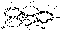
A vaso-occlusive device (10) includes a microcoil (12) formed into a minimum energy state secondary configuration comprising a plurality of curved segments (14a,14b,24), each defining a discrete axis (16), whereby the device, in its minimum energy state configuration, defines multiple axes. In a preferred embodiment, the minimum energy state secondary configuration comprises a plurality of tangentially-interconnected, substantially circular loops (14a,14b) defining a plurality of discrete axes (16). In an alternative embodiment, the minimum energy state secondary configuration defines a wave-form like structure comprising a longitudinal array of laterally-alternating open loops (24) defining a plurality of separate axes (16). In either embodiment, the device (10), in its minimum energy state secondary configuration, has a dimension that is substantially larger than the largest dimension of the vascular site in which the device is to be deployed. Thus, when the device (10) is deployed in an aneurysm (40) , the confinement of the device (10) within the aneurysm (40) causes the device (10) to assume a three-dimensional configuration that has a higher energy state than the minimum energy state.
Description
The cross reference of related application
Inapplicable.The research of federal funding or exploitation
Inapplicable.
Background of invention
The present invention relates generally to angiemphraxis Apparatus and method for field.More specifically, the present invention relates to form the Apparatus and method for that thromboembolism comes occluding vascular by the target site in blood vessel (as aneurysm).
Under a lot of clinical settings, want to obtain blood vessel embolism.For example, blood vessel embolism has been used to control angiorrbagia, blocks the blood supply to tumor, occluding vascular aneurysm, especially intracranial aneurysm.In recent years, be used for the treatment of aneurysmal blood vessel embolism and caused very big attention.Several different form of therapy have been adopted in the prior art.Dormandy for example, people's such as Jr. United States Patent (USP) 4,819,637 has been described a kind of vascular embolization system that utilizes separable balloon, and described balloon is delivered to aneurysm site by endovascular conduit.Balloon is carried in the aneurysm of catheter tip, and owing to solidified liquid (typically being polymer resin or gel) expands with the obstructing arterial tumor in aneurysm.By soft traction on conduit balloon is separated with conduit then.Though the thromboembolism equipment of balloon type can block the aneurysm of a lot of types effectively, solidify the back at solidified liquid and be difficult to its recovery or mobile, unless fill contrast material, be difficult to it is visual.And, also exist balloon in the expansion process to break and too early with the danger of conduit disengaging.
Another kind of mode is directly to the vascular site injecting fluid polymer plug agent that will block.A class I liquid I polymer that uses in the direct injection technology is as rapid polymerization liquid, as cyano-acrylate resin, and isobutyl cyanoacrylate especially, this polymer is delivered to target site with the form of liquid, then in the original place polymerization.Alternatively, used a kind of liquid polymers that from carrier solution, is precipitated out at target site.An example of this class suppository be mixed with bismuth oxide and be dissolved in cellulose acetate polymer in the dimethyl sulfoxide (DMSO).Another kind of suppository is the glycol copolymer that is dissolved among the DMSO.After blood contacted, DMSO just spread apart, and polymer precipitation comes out and quick-hardening becomes to have the embolic mass of aneurysm shape.Other example of the material that adopts in this " direct injection " method is disclosed in following United States Patent (USP): people's such as Paesztor 4,551,132; People's such as Leshchiner 4,795,741; People's such as Ito 5,525,334; With people's such as Greff 5,580,568.
Proved that the agent of direct injection liquid polymer plug is very difficult in practice.For example, to move to contiguous blood vessel from aneurysm be exactly a problem to polymeric material.In addition, a kind of contrast medium of visual needs of embolism materials mixes with it, and embolism materials that selection is mated mutually and contrast medium can cause performance to be affected and be lower than optimum efficiency.And the configuration of accurately controlling the polymerization embolism materials is very difficult, can cause the risk of incorrect placement of this material and/or premature setting.And,, be difficult to it is moved or reclaims in case embolism materials is configured and solidifies.
The method that another kind has prospect is to use thrombosed little coil.Coil can be by biocompatible metals alloy (typically being platinum and tungsten) or suitable polymers manufacturing slightly for this.If adopt the metal manufacturing, coil can be provided to improve thrombosis by polyester fiber.Coil is configured by the microtubular that arrives vascular site.The example of little coil is disclosed in the following United States Patent (USP): people's such as Ritchart 4,994,069; People's such as Guglielmi 5,122,136; People's such as Butler 5,133,731; People's such as Chee 5,226,911; People's such as Chee 5,304,194; 5,312,415 of Palermo; People's such as Phelps 5,382,259; Dormandy, people's such as Jr. 5,382,260; Dormandy, people's such as Jr. 5,476,472; 5,578,074 of Mirigian; 5,582,619 of Ken; 5,624,461 of Mariant; People's such as Mariant 5,639,277; 5,658,308 of Snyder; 5,690,667 of Gia; People's such as McGurk 5,690,671; People's such as Mirigian 5,700,258; People's such as Berenstein 5,718,711; People's such as Taki 5,891,058; People's such as Ken 6,013,084; People's such as Rosenbluth 6,015,424; With people's such as Mariant Des.427,680.
Though little coil component of a lot of prior aries has obtained some successes in treatment has the microaneurysm of narrow relatively neck, but the little coil angiemphraxis device that it has been recognized that the most normal employing is in the aneurysm of wide neck, especially in brain, also do not reach satisfied result.This has caused the development of three-dimensional little coil component, as those at 5,645,558 of the disclosed device of following United States Patent (USP): Horton; People's such as Pham 5,911,731; With 5,957,948 (latter two belong to the device that a class is called as " three-dimensional Guglielmi detachable coil " or " 3D-GDC ' s ") of Mariant.Referring to people such as for example Tan " The Feasibility of Three-Dimensional Guglielmi Detachable Coil for Embolisation of Wide NeckCerebral ANEURYSMS; " Interventional Neuroradiology, Vol.6, pp.53-57 (June, 2000); Cloft et al., " Use of Three-Dimensional GuglielmiDetachable Coils in the Treatment of Wide-necked Cerebral Aneurysms; " American Journal of Neuroradiology, Vol.21, pp.1312-1314 (August, 2000).
Typical three-dimensional little coil is formed by one section tinsel, and tinsel at first forms the one-level configuration of spiral winding, forms then to belong to secondary configuration a kind of in the multiple 3D shape.The minimum energy state of this type of little coil is its three-dimensional secondary configuration.In the time of in being configured in aneurysm, these devices present 3-d modelling, typically are some spheric configuration, are in or are slightly larger than the minimum energy state of secondary configuration.Because the overall size of these devices when its non-minimum energy state configuration is approximately equal to or less than aneurysmal inside dimension, so do not have thing to limit this device because blood flow power moves in aneurysm or upset.
In some of these three-dimension devices (as people's such as Guglielmi United States Patent (USP) 5,122,136), secondary configuration this as helical form or form some similar type of longitudinal axis.When having the device that can be called as " vertically " secondary configuration when being configured in the aneurysm, these devices form three-dimensional non-minimum energy state configuration, but in case after being configured, they promptly show the trend that is returned to minimum energy state.This causes again because the compressing of " coin stacking " (coin stacking) (that is, getting back to the deuterostrophies configuration), thereby allows aneurysmal heavy logical.
Therefore for a long time need but do not obtain so little coil angiemphraxis device as yet, it has the advantage of little coil component of many prior aries, but can be effectively used to treat the aneurysm of many different size configurations, and especially those have the aneurysm of big neck breadth degree.For such device advantageously, compatible with the little coil delivery mechanism of microtubular during use with existing leading line, and can make with the expense suitable with little coil component of prior art.
Summary of the invention
Briefly, the present invention is a kind of little coil angiemphraxis device, and this device has the minimum energy state secondary configuration that comprises a plurality of bending sections, and each bending section defines a discrete axle, and the device that is in minimum energy state configuration thus defines a plurality of axles.More specifically, each bending section defines a plane and one and the vertical substantially axle in this plane.
In an especially preferred embodiment, the present invention is the little loop construction with minimum energy state secondary configuration of an elongation, and this minimum energy state secondary configuration defines a plurality of interconnected tangently and almost circular coils that define a plurality of discrete axles.In a kind of form of preferred embodiment, described circular basically closing coil is coplane basically, and defines substantially parallel axle.That is to say self basic coplane by limit flat of described bending section.In the another kind of form in preferred embodiments, every pair of adjacent coil has formed a low-angle, is not more than about 90 °, preferably is not more than about 45 ° angle thereby their axles have separately formed one between them.
In an alternate embodiment, little loop construction has minimum energy state secondary configuration, this minimum energy state configuration secondary configuration defines the structure of the similar waveform of a vertical array that comprises horizontal alternative open stich, and described open stich defines a plurality of discrete axles.In described preferred embodiment, alternate embodiment can be first kind of form, coil coplane and substantially parallel axes separately basically wherein, perhaps can be second kind of form, wherein every pair of adjacent coil has formed a low-angle, is not more than about 90 °, preferably is not more than about 45 ° angle thereby their axles have separately formed one between them.
In any one embodiment, the size of devices that is in its minimum energy state secondary configuration than this device will dispose wherein the spatial full-size of blood vessel big abundant (preferably greatly at least about 25%).Therefore, in the time of in this device is configured in such as aneurysmal vascular site, the restriction to device in this position causes this device to present the 3-d modelling higher than minimum energy state.Because the minimum energy state of device is than the space of using it therein big (one dimension at least), so the device that is configured is by being limited to be returned to minimum energy state configuration with tight contact of aneurysm wall.Therefore, this device still and aneurysm wall surface on every side be connected, thereby make by moving of causing of blood flow power or upset reduces to minimum.And minimum energy state secondary configuration (configuration that this device is attempted to be returned to) is not the structure that helps " coin stacking ", thereby the degree that compresses that is experienced is reduced to minimum.
The invention provides effective thromboembolism of the blood vessel structure (especially aneurysm) with a variety of shape and size, this will be better understood in detailed description subsequently.When being used for wide carotid aneurysm, especially has advantage.And the present invention can adopt conventional configuration mechanism such as microtubular and leading line to be configured, and this will be described in more detail in bottom.
Summary of drawings
Fig. 1 is the perspective view according to little coil angiemphraxis device of the preferred embodiments of the invention;
Fig. 2 is the partial view of the described device of Fig. 1 label 2 specified portions in Fig. 1;
Fig. 3 and 4 is the partial view according to little coil angiemphraxis device of the another kind of form of the preferred embodiments of the invention;
Fig. 5 is the plane graph according to little coil angiemphraxis device of alternate embodiment of the present invention;
Fig. 6 is the front view of the present invention in enter the process that wide carotid aneurysm is configured by microtubular;
Fig. 7 is the perspective view that is used to make the heat treatment fixing device of the preferred embodiments of the invention.
Detailed Description Of The Invention
At first, shown a kind of little coil angiemphraxis device 10 according to the preferred embodiments of the invention referring to figs. 1 to 4 and 8.Device 10 comprises the tinsel (Fig. 2) of one-level configuration of the formation spiral winding 12 of one section appropriate length.The various alloys that device 10 suitable materials comprised platinum, rhodium, palladium, rhenium, tungsten, gold, silver, tantalum and these metals.Also can adopt other rustless steel of various Surgical Grade.Preferable material comprises platinum/tungsten alloy of being called as platinum 479 (92%Pt, 8%W can be from Sigmund Cohn, of Mount Vernon, NY obtains) and titanium/nickel alloy (as being become the titanium/nickel alloy of " Nitinol ").Another kind of may favourable material be the composite wire that comprises high resiliency metal and highly radiopaque metal.This composite wire also can be resisted permanent deformation.An example of this composite wire is the product that comprises the inner core of nitinol outer layer and pure standard level platinum, can be from Sigmund Cohn, and of Mount Vernon, NY and Anomet Products, of Shrewsbury, MA. obtains.Can adopt the wire diameter of about 0.0125mm to about 0.150mm.
The diameter of little coil 12 typically at about 0.125mm to about 0.625mm scope, be about 0.25mm about 0.40mm extremely for most of neural and vascular applications preferred range.The axial length of little coil 12 can be the random length of about 5mm between about 1000mm, typically is extremely about 400mm of about 20mm.
The one-level of carrying out little coil 12 under tension force is twined.The pitch that amount of tension and one-level are twined has determined the hardness of little coil 12.These parameters can change the little coil that has different hardness along its length to form along the length of little coil 12, and this little coil has advantage in some applications.
Little coil 12 is formed the secondary configuration that comprises a plurality of bending sections, and each bending section defines an axle, thereby little coil 12 defines a plurality of axles.More specifically, each bending section defines a plane and one and the vertical substantially axle in this plane.In the preferred embodiment of Fig. 1 to 4, bending section is interconnection tangently and basic be circular the coil 14a, the 14b that define a plurality of axles 16 that separate.In a kind of form in preferred embodiments, as shown in Figure 1, described almost circular coil 14a, 14b be coplane basically, and defines substantially parallel axle 16.In the another kind of form of preferred embodiment, shown in Fig. 3 and 4, every couple of adjacent coil 14a, 14b has formed a low-angle, is not more than about 90 ° between them, preferably is not more than about 45 ° angle (θ 1, θ 2, θ 3 and θ 4) thereby their axles 16 have separately formed one.
The preferred embodiments of the invention typically comprise pair of end portions coil 14a and at least one intermediate coil 14b.Typically, nearly 4 intermediate coil 14b can be arranged, this depends on by the vascular site of thromboembolism, still also can use nearly 6 or more intermediate coil for very big vascular site.The diameter of intermediate coil approximates the maximum gauge of target vascular site (as aneurysm), and the diameter of end coil 14a is because below with purpose of description and smaller (preferably, little about 1.5mm).
The little coil 12 of one-level forms secondary configuration by heat treatment, and this is well known in the art.For example, annealed one-level coil can stand specified a period of time under degenerate temperature then at first by being arranged in secondary structure on the mandrel that twines or be wound on a shape and sizeable refractory material.For example for platinum 479, annealing temperature is about 500 ℃ to about 1000 ℃, preferred about 670 ℃, keeps cool to room temperature, and ultrasonic cleaning then about 30 to 90 minutes, preferred about 60 minutes.Thereby make permanent synthesizing secondary configuration, this secondary configuration becomes the minimum energy state configuration of little coil 12.
Fig. 7 has shown the heat treatment fixing device 50 that uses in the manufacture process of preferred version of the present invention.Fixing device 50 is made by refractory material, comprises base 52, and this base has the surface that is provided for the mandrel that secondary twines thereon.This mandrel comprises a plurality of surperficial upwardly extending winding pin 54a, 54b from base 52.Example fixation equipment 50 shown in the accompanying drawing has roughly six pins by the hexagon arranged in patterns.There are two ends adjacent one another are to twine pin and four middle pin 54b that twine.There is a pair of fastening bolt 56 to be used for fixing the end of one-level coil 12 at a end near fixing device.
The diameter of end winding pin 54a twines the diameter of pin 54b slightly less than the centre, to reach above-mentioned magnitude relationship.Distance between a pin 54a and 54b slightly larger in diameter than one-level coil 12 is so that only have a circle one-level coil by having the pin of each secondary coil winding.Therefore, each back one circle of secondary coil is stacked on the top of last circle.This has eliminated any straight part of secondary coil, and described straight part can trend towards pushing coil to female tremulous pulse in layoutprocedure.
In the secondary winding process, one-level coil 12 remains under the tension force.Amount of tension can be adjusted with the coil 14a that controls little coil 12, the extent of rebound of 14b.
Little coil 12 carries out that secondary twines so that when twining on the continuous pin of little coil 12 each on fixing device, coil 14a, 14b can reverses direction.This has guaranteed that coil can coin stacking, and in case be configured the back they with regard to random dispersion in whole aneurysm.And in preferred embodiments, each circle twines complete 360 ° before next circle twines.This has guaranteed that each circle is settled fully before little coil 12 reverses direction in aneurysm.Because circle contact completely makes the loop strength maximum, the coil uniformly distributed.
Fig. 5 has shown the little coil angiemphraxis device 20 according to alternate embodiment of the present invention.This embodiment comprises the little coil 22 of one-level, and the little coil of this one-level forms the secondary minimum energy state configuration that limits similar waveform configuration, and the structure of described similar waveform comprises the laterally alternative vertical array that defines the open stich 24 of a plurality of minutes vertical shafts.As in preferred embodiments, alternate embodiment can be first kind of form, wherein coil 24 basic coplanes and axle 26 separately are substantially parallel, perhaps can be second kind of form, wherein every pair of adjacent coil 24 has formed a low-angle, is not more than about 90 °, preferably is not more than about 45 ° angle thereby their axles 26 have separately formed one between them.Material, size and the method preferred embodiment with above-mentioned aspect all material of making this alternate embodiment is similar.
Fig. 6 has shown the method for the present invention that adopts.In use, the near-end of little coil 12 (or 22) is connected with the far-end of leading line or microtubular (not having to show).Can be by any connection the in many modes as known in the art, as following United States Patent (USP) illustrated, the disclosure that comprises these patents here clearly for your guidance: people's such as Geremia 5,108,407; People's such as Guglielmi 5,122,136; 5,234,437 of Sepetka; 5,261,916 of Engelson; Twyford, people's such as Jr. 5,304,195; 5,312,415 of Palermo; People's such as Pham 5,423,829; 5,522,836 of Palermo; People's such as Northrup 5,645,564; 5,725,546 of Samson; 5,800,453 of Gia; People's such as Sepetka 5,814,062; People's such as Lee 5,911,737; People's such as Saadat 5,989,242; People's such as Jacobsen 6,022,369; .Diaz wait people's 6,063,100; People's such as Lulo 6,068,644; With people's such as Lee 6,102,933.
Make target vascular site visual by well-known usual manner in this area.Target vascular site can be the aneurysm 40 that makes female tremulous pulse 42 bifurcateds.Aneurysm 40 has a dome 44 that links to each other with bifurcated artery by neck 46.Conduit 30 passes through in blood vessel, up to the dome 44 that enters aneurysm 40 via neck 46.By means of leading line or microtubular little coil 12 is passed through conduit 30, enter the dome 44 of aneurysm 40 up to little coil 12.
The small-sized end coil 14a that is positioned at little coil 12 far-ends at first enters aneurysm.This helps the proper arrangement of first coil, because less size remains in the aneurysmal neck 46 first coil, avoids female tremulous pulse 42.
Intermediate coil 14b enters aneurysm then.Because their size is fit to aneurysm, can launch reposefully with the minimized friction freedom against aneurysm wall.Because the secondary configuration of little coil 12 is coplane basically, all intermediate coils apply power to the wall of aneurysm dome 44, thereby have improved little coil because the resistance that blood pulses flows and is moved.
When little coil 12 entered aneurysm, it attempted to present its secondary configuration.Yet because it is bigger than aneurysm to be in little coil of secondary configuration, it is restricted to the deployed configuration that trend is filled aneurysm internal volume.In this deployed configuration, little coil is in than the abundant big energy state of its minimum energy state.Therefore, when this device disposes in such as aneurysmal vascular site, cause this device to present the 3-d modelling higher than minimum energy state to the restriction of device in this position.Because the minimum energy state of device is than the space of using it therein big (one dimension at least), the device that is configured is by being limited to be returned to minimum energy state configuration with tight contact of aneurysm wall.Therefore, this device still is connected with on every side aneurysm wall surface, thereby makes by moving of causing of blood flow power or upset reduces to minimum.And minimum energy state secondary configuration (configuration that this device is attempted to be returned to) is not the configuration that helps " coin stacking ", thereby the degree that compresses that is stood is reduced to minimum.
The small-sized end coil 14a that is positioned at little coil 12 near-ends enters aneurysm at last.After little coil is disposed fully, by any suitable method well-known in the art it is controllably separated with leading line, thereby allow to reclaim microtubular or leading line, little coil is stayed suitable place with the thromboembolism aneurysm.After separation, proximal coil 14a curls and enters the neck 46 of aneurysm 40, avoids female tremulous pulse 42.
Like this, the present invention has shown several advantages of the three-dimensional little coil that is better than prior art.For example, because the existence that passes across the coil of neck has increased the covering of aneurysm neck, and any part of device is invaded the probability of female tremulous pulse and is reduced.The secondary coil configuration also provides configuration more stably, in case after being configured, device just shows the more on the whole resistance that coil is compressed, thereby has improved the positional stability of the blood flow that faces pulsation.This stability reaches by total friction lower between device and aneurysm wall.And coil allows device to keep complicated shape in aneurysm, improved thromboembolism at aneurysm random distribution everywhere.
Although this paper has described the preferred embodiments of the invention and alternate embodiment, those skilled in the relevant art will understand their many variations and modification.For example, can find, other secondary configuration that is different from those secondary configuration as herein described can reach the significant advantage of the present invention that most of (if not all) is used for typical aneurysm treatment, or be proved to be especially favourable in concrete clinical practice.Also have, for concrete application, size also may be with disclosed herein different, advantageously to be employed with material.These and other variation and modification be to be regarded as be within the spirit and scope of the invention, as subsequently claims limited.
Claims (18)
1. little coil angiemphraxis device, described device comprises the little coil that forms minimum energy state secondary configuration, this secondary configuration comprises a plurality of bending sections that define a discrete axle respectively, and the described thus device that is in minimum energy state configuration defines a plurality of axles.
2. device as claimed in claim 1, wherein each bending section defines a plane and is basically perpendicular to this planar axle.
3. device as claimed in claim 1, wherein said a plurality of substantially parallel axes.
4. device as claimed in claim 1, every pair of wherein said a plurality of adjacent shaft forms acute angle.
5. device as claimed in claim 1, wherein said bending section is interconnective coil airtightly substantially, substantially tangent.
6. device as claimed in claim 1, wherein said bending section are the open stich of similar waveform.
7. device as claimed in claim 1, wherein said little coil is formed by composite wire.
8. device as claimed in claim 7, wherein said composite wire comprise radiopaque metal and high resiliency metal.
9. device as claimed in claim 8, wherein said composite wire comprises platinum core and nitinol outer layer.
10. little coil angiemphraxis device, described device comprises the little coil that forms minimum energy state secondary configuration, this secondary configuration comprises a plurality of interconnected tangently and almost circular coils, and each coil defines a plane and is basically perpendicular to this planar discrete axle.
11. device as claimed in claim 10, wherein said substantially parallel axes.
12. device as claimed in claim 10, wherein every pair of adjacent shaft forms acute angle.
13. device as claimed in claim 10, wherein said little coil is formed by composite wire.
14. device as claimed in claim 13, wherein said composite wire comprise radiopaque metal and high resiliency metal.
15. device as claimed in claim 14, wherein said composite wire comprises platinum core and nitinol outer layer.
16. the aneurysmal method of thromboembolism said method comprising the steps of:
(a) provide little coil angiemphraxis device, this device comprises the little coil that forms minimum energy state secondary configuration, this secondary configuration comprises a plurality of bending sections that define a discrete axle respectively, the described thus device that is in minimum energy state configuration defines a plurality of axles, and has at least one size greater than the aneurysm inside dimension; With
(b) at the described device of aneurysmal internal configurations, so that described device to be to be comprised in the aneurysm than the sufficiently high configuration of minimum energy state, described thus device is by being limited to be returned to minimum energy state configuration with contacting of aneurysm wall.
17. method as claimed in claim 16, the wherein said device that is in minimum energy state secondary configuration comprise a plurality of interconnected tangently and almost circular coils, each coil defines a discrete axle.
18. method as claimed in claim 16, the wherein said device that is in minimum energy state secondary configuration comprises the open stich of a plurality of interconnected similar waveforms, and each coil defines a discrete axle.
Priority Applications (1)
| Application Number | Priority Date | Filing Date | Title |
|---|---|---|---|
| CN201510300352.3A CN105286937A (en) | 2001-11-07 | 2001-11-07 | Vascular obstruction device |
Applications Claiming Priority (1)
| Application Number | Priority Date | Filing Date | Title |
|---|---|---|---|
| PCT/US2001/050970 WO2003039376A1 (en) | 2001-11-07 | 2001-11-07 | Microcoil vaso-occlusive device with multi-axis secondary configuration |
Related Child Applications (3)
| Application Number | Title | Priority Date | Filing Date |
|---|---|---|---|
| CN201510300352.3A Division CN105286937A (en) | 2001-11-07 | 2001-11-07 | Vascular obstruction device |
| CN 200710005268 Division CN101045005A (en) | 2001-11-07 | 2001-11-07 | Microcoil vaso-occlusive device with multi-axis secondary configuration |
| CN2010105013705A Division CN102038533A (en) | 2001-11-07 | 2001-11-07 | Microcoil vessel obstruction device with multi-axis secondary configuration |
Publications (1)
| Publication Number | Publication Date |
|---|---|
| CN1558741A true CN1558741A (en) | 2004-12-29 |
Family
ID=21743179
Family Applications (1)
| Application Number | Title | Priority Date | Filing Date |
|---|---|---|---|
| CNA018237738A Pending CN1558741A (en) | 2001-11-07 | 2001-11-07 | Microcoil vaso-occlusive device with multi-axis secondary configuration |
Country Status (10)
| Country | Link |
|---|---|
| EP (2) | EP1448105B1 (en) |
| JP (1) | JP4109627B2 (en) |
| CN (1) | CN1558741A (en) |
| AT (1) | ATE452585T1 (en) |
| AU (1) | AU2002236676B2 (en) |
| BR (1) | BR0117168A (en) |
| CA (1) | CA2466017C (en) |
| DE (1) | DE60140905D1 (en) |
| ES (1) | ES2338635T3 (en) |
| WO (1) | WO2003039376A1 (en) |
Cited By (5)
| Publication number | Priority date | Publication date | Assignee | Title |
|---|---|---|---|---|
| CN100448412C (en) * | 2006-04-29 | 2009-01-07 | 朱国华 | Operative clip of titanium and its making process |
| CN101610723B (en) * | 2007-02-07 | 2012-04-25 | 迈科洛斯血管腔内治疗公司 | Winding mandrel for vasoocclusive coils |
| CN103549987A (en) * | 2007-11-09 | 2014-02-05 | 德普新赛斯产品公司 | Tethered coil for treatment of body lumens |
| CN101677821B (en) * | 2007-03-13 | 2014-05-14 | 泰科保健集团有限合伙公司 | Implant and mandrel |
| CN108697427A (en) * | 2016-03-07 | 2018-10-23 | 田中贵金属工业株式会社 | The manufacturing method of embolism spring ring and embolism spring ring |
Families Citing this family (4)
| Publication number | Priority date | Publication date | Assignee | Title |
|---|---|---|---|---|
| US7029486B2 (en) | 2000-09-26 | 2006-04-18 | Microvention, Inc. | Microcoil vaso-occlusive device with multi-axis secondary configuration |
| US9622751B2 (en) | 2008-08-06 | 2017-04-18 | Boston Scientific Scimed, Inc. | Vaso-occlusive devices with textured surfaces |
| CN106102600B (en) | 2014-02-27 | 2019-09-27 | 因库麦迪斯有限公司 | Embolism framework microcoils |
| US10307168B2 (en) | 2015-08-07 | 2019-06-04 | Terumo Corporation | Complex coil and manufacturing techniques |
Family Cites Families (49)
| Publication number | Priority date | Publication date | Assignee | Title |
|---|---|---|---|---|
| US427680A (en) | 1890-05-13 | good-son | ||
| HU184722B (en) | 1980-02-18 | 1984-10-29 | Laszlo Lazar | Therapeutically suitable silicone rubber mixture and therapeuticaid |
| US4795741A (en) | 1987-05-06 | 1989-01-03 | Biomatrix, Inc. | Compositions for therapeutic percutaneous embolization and the use thereof |
| US4819637A (en) | 1987-09-01 | 1989-04-11 | Interventional Therapeutics Corporation | System for artificial vessel embolization and devices for use therewith |
| US4994069A (en) | 1988-11-02 | 1991-02-19 | Target Therapeutics | Vaso-occlusion coil and method |
| US5122136A (en) | 1990-03-13 | 1992-06-16 | The Regents Of The University Of California | Endovascular electrolytically detachable guidewire tip for the electroformation of thrombus in arteries, veins, aneurysms, vascular malformations and arteriovenous fistulas |
| US5108407A (en) | 1990-06-08 | 1992-04-28 | Rush-Presbyterian St. Luke's Medical Center | Method and apparatus for placement of an embolic coil |
| US5133731A (en) | 1990-11-09 | 1992-07-28 | Catheter Research, Inc. | Embolus supply system and method |
| US5226911A (en) | 1991-10-02 | 1993-07-13 | Target Therapeutics | Vasoocclusion coil with attached fibrous element(s) |
| US5304194A (en) | 1991-10-02 | 1994-04-19 | Target Therapeutics | Vasoocclusion coil with attached fibrous element(s) |
| US5234437A (en) | 1991-12-12 | 1993-08-10 | Target Therapeutics, Inc. | Detachable pusher-vasoocclusion coil assembly with threaded coupling |
| US5261916A (en) | 1991-12-12 | 1993-11-16 | Target Therapeutics | Detachable pusher-vasoocclusive coil assembly with interlocking ball and keyway coupling |
| WO1993011719A1 (en) | 1991-12-12 | 1993-06-24 | Target Therapeutics, Inc. | Detachable pusher-vasoocclusive coil assembly with interlocking coupling |
| US5312415A (en) | 1992-09-22 | 1994-05-17 | Target Therapeutics, Inc. | Assembly for placement of embolic coils using frictional placement |
| US5382259A (en) | 1992-10-26 | 1995-01-17 | Target Therapeutics, Inc. | Vasoocclusion coil with attached tubular woven or braided fibrous covering |
| US5382260A (en) | 1992-10-30 | 1995-01-17 | Interventional Therapeutics Corp. | Embolization device and apparatus including an introducer cartridge and method for delivering the same |
| US5690666A (en) | 1992-11-18 | 1997-11-25 | Target Therapeutics, Inc. | Ultrasoft embolism coils and process for using them |
| AU681073B2 (en) * | 1992-11-19 | 1997-08-21 | Target Therapeutics, Inc. | Large diameter vasoocclusion coil |
| US5800453A (en) | 1993-04-19 | 1998-09-01 | Target Therapeutics, Inc. | Detachable embolic coil assembly using interlocking hooks and slots |
| US5423829A (en) | 1993-11-03 | 1995-06-13 | Target Therapeutics, Inc. | Electrolytically severable joint for endovascular embolic devices |
| JP2535785B2 (en) | 1994-06-03 | 1996-09-18 | 工業技術院長 | Vascular embolic agent |
| US5725546A (en) | 1994-06-24 | 1998-03-10 | Target Therapeutics, Inc. | Detachable microcoil delivery catheter |
| US5549624A (en) | 1994-06-24 | 1996-08-27 | Target Therapeutics, Inc. | Fibered vasooclusion coils |
| US5522836A (en) | 1994-06-27 | 1996-06-04 | Target Therapeutics, Inc. | Electrolytically severable coil assembly with movable detachment point |
| US5690671A (en) | 1994-12-13 | 1997-11-25 | Micro Interventional Systems, Inc. | Embolic elements and methods and apparatus for their delivery |
| US5814062A (en) | 1994-12-22 | 1998-09-29 | Target Therapeutics, Inc. | Implant delivery assembly with expandable coupling/decoupling mechanism |
| US5578074A (en) | 1994-12-22 | 1996-11-26 | Target Therapeutics, Inc. | Implant delivery method and assembly |
| US5645558A (en) | 1995-04-20 | 1997-07-08 | Medical University Of South Carolina | Anatomically shaped vasoocclusive device and method of making the same |
| US5911731A (en) | 1995-04-20 | 1999-06-15 | Target Therapeutics, Inc. | Anatomically shaped vasoocclusive devices |
| US5639277A (en) | 1995-04-28 | 1997-06-17 | Target Therapeutics, Inc. | Embolic coils with offset helical and twisted helical shapes |
| US5645564A (en) | 1995-05-22 | 1997-07-08 | Regents Of The University Of California | Microfabricated therapeutic actuator mechanisms |
| US5624461A (en) | 1995-06-06 | 1997-04-29 | Target Therapeutics, Inc. | Three dimensional in-filling vaso-occlusive coils |
| US5989242A (en) | 1995-06-26 | 1999-11-23 | Trimedyne, Inc. | Therapeutic appliance releasing device |
| US5582619A (en) | 1995-06-30 | 1996-12-10 | Target Therapeutics, Inc. | Stretch resistant vaso-occlusive coils |
| US6013084A (en) | 1995-06-30 | 2000-01-11 | Target Therapeutics, Inc. | Stretch resistant vaso-occlusive coils (II) |
| US5580568A (en) | 1995-07-27 | 1996-12-03 | Micro Therapeutics, Inc. | Cellulose diacetate compositions for use in embolizing blood vessels |
| US5658308A (en) | 1995-12-04 | 1997-08-19 | Target Therapeutics, Inc. | Bioactive occlusion coil |
| JP3784112B2 (en) | 1996-08-15 | 2006-06-07 | 株式会社カネカメディックス | Coiled embolic material |
| US5690667A (en) | 1996-09-26 | 1997-11-25 | Target Therapeutics | Vasoocclusion coil having a polymer tip |
| US5911737A (en) | 1997-02-28 | 1999-06-15 | The Regents Of The University Of California | Microfabricated therapeutic actuators |
| US6322576B1 (en) * | 1997-08-29 | 2001-11-27 | Target Therapeutics, Inc. | Stable coil designs |
| US6022369A (en) | 1998-02-13 | 2000-02-08 | Precision Vascular Systems, Inc. | Wire device with detachable end |
| US6068644A (en) | 1998-03-10 | 2000-05-30 | Cordis Corporation | Embolic coil hydraulic deployment system having improved catheter |
| US6063100A (en) | 1998-03-10 | 2000-05-16 | Cordis Corporation | Embolic coil deployment system with improved embolic coil |
| US6015424A (en) | 1998-04-28 | 2000-01-18 | Microvention, Inc. | Apparatus and method for vascular embolization |
| US6165194A (en) * | 1998-07-24 | 2000-12-26 | Micrus Corporation | Intravascular flow modifier and reinforcement device |
| AU6288799A (en) * | 1998-10-09 | 2000-05-01 | Cook Incorporated | Vasoocclusion coil device having a core therein |
| US6280457B1 (en) * | 1999-06-04 | 2001-08-28 | Scimed Life Systems, Inc. | Polymer covered vaso-occlusive devices and methods of producing such devices |
| US6790218B2 (en) * | 1999-12-23 | 2004-09-14 | Swaminathan Jayaraman | Occlusive coil manufacture and delivery |
-
2001
- 2001-11-07 ES ES01986219T patent/ES2338635T3/en not_active Expired - Lifetime
- 2001-11-07 CA CA002466017A patent/CA2466017C/en not_active Expired - Fee Related
- 2001-11-07 CN CNA018237738A patent/CN1558741A/en active Pending
- 2001-11-07 AT AT01986219T patent/ATE452585T1/en not_active IP Right Cessation
- 2001-11-07 EP EP01986219A patent/EP1448105B1/en not_active Expired - Lifetime
- 2001-11-07 AU AU2002236676A patent/AU2002236676B2/en not_active Ceased
- 2001-11-07 WO PCT/US2001/050970 patent/WO2003039376A1/en active Application Filing
- 2001-11-07 EP EP09015616.7A patent/EP2163212B1/en not_active Expired - Lifetime
- 2001-11-07 BR BR0117168-2A patent/BR0117168A/en not_active IP Right Cessation
- 2001-11-07 DE DE60140905T patent/DE60140905D1/en not_active Expired - Lifetime
- 2001-11-07 JP JP2003541472A patent/JP4109627B2/en not_active Expired - Fee Related
Cited By (7)
| Publication number | Priority date | Publication date | Assignee | Title |
|---|---|---|---|---|
| CN100448412C (en) * | 2006-04-29 | 2009-01-07 | 朱国华 | Operative clip of titanium and its making process |
| CN101610723B (en) * | 2007-02-07 | 2012-04-25 | 迈科洛斯血管腔内治疗公司 | Winding mandrel for vasoocclusive coils |
| CN102599956A (en) * | 2007-02-07 | 2012-07-25 | 迈科洛斯血管腔内治疗有限责任公司 | Winding mandrel for vasoocclusive coils |
| CN101677821B (en) * | 2007-03-13 | 2014-05-14 | 泰科保健集团有限合伙公司 | Implant and mandrel |
| CN103549987A (en) * | 2007-11-09 | 2014-02-05 | 德普新赛斯产品公司 | Tethered coil for treatment of body lumens |
| CN103549987B (en) * | 2007-11-09 | 2015-11-25 | 德普新赛斯产品公司 | The tethered coil for the treatment of body cavity |
| CN108697427A (en) * | 2016-03-07 | 2018-10-23 | 田中贵金属工业株式会社 | The manufacturing method of embolism spring ring and embolism spring ring |
Also Published As
| Publication number | Publication date |
|---|---|
| JP2005507300A (en) | 2005-03-17 |
| EP2163212A1 (en) | 2010-03-17 |
| BR0117168A (en) | 2004-10-26 |
| AU2002236676B2 (en) | 2008-02-28 |
| EP1448105B1 (en) | 2009-12-23 |
| WO2003039376A1 (en) | 2003-05-15 |
| ES2338635T3 (en) | 2010-05-11 |
| JP4109627B2 (en) | 2008-07-02 |
| EP1448105A1 (en) | 2004-08-25 |
| ATE452585T1 (en) | 2010-01-15 |
| EP2163212B1 (en) | 2015-09-23 |
| DE60140905D1 (en) | 2010-02-04 |
| CA2466017C (en) | 2008-10-28 |
| CA2466017A1 (en) | 2003-05-15 |
Similar Documents
| Publication | Publication Date | Title |
|---|---|---|
| US7331974B2 (en) | Microcoil vaso-occlusive device with multi-axis secondary configuration | |
| US8323306B2 (en) | Microcoil vaso-occlusive device with multi-axis secondary configuration | |
| US7033374B2 (en) | Microcoil vaso-occlusive device with multi-axis secondary configuration | |
| JP4961349B2 (en) | Embolization coil, embolization coil manufacturing method, medical device | |
| CN100423697C (en) | Filamentous embolic device with expansible elements | |
| CN1250167C (en) | Filamentous embolic device with expansible elements | |
| US9089405B1 (en) | Three-dimensional complex coil | |
| JP2000517222A (en) | Embolization device for placement in blood vessels | |
| CN1558741A (en) | Microcoil vaso-occlusive device with multi-axis secondary configuration | |
| US20040006362A1 (en) | Uniaxial multifilar vaso-occlusive device with high stretch resistance and low buckling strength | |
| CN101045005A (en) | Microcoil vaso-occlusive device with multi-axis secondary configuration | |
| AU2002236676A1 (en) | Microcoil vaso-occlusive device with multi-axis secondary configuration | |
| CN102038533A (en) | Microcoil vessel obstruction device with multi-axis secondary configuration | |
| CN105286937A (en) | Vascular obstruction device |
Legal Events
| Date | Code | Title | Description |
|---|---|---|---|
| C06 | Publication | ||
| PB01 | Publication | ||
| C10 | Entry into substantive examination | ||
| SE01 | Entry into force of request for substantive examination | ||
| C12 | Rejection of a patent application after its publication | ||
| RJ01 | Rejection of invention patent application after publication |
Open date: 20041229 |