CN1514800A - Landing stage door device of elevator - Google Patents
Landing stage door device of elevator Download PDFInfo
- Publication number
- CN1514800A CN1514800A CNA028115651A CN02811565A CN1514800A CN 1514800 A CN1514800 A CN 1514800A CN A028115651 A CNA028115651 A CN A028115651A CN 02811565 A CN02811565 A CN 02811565A CN 1514800 A CN1514800 A CN 1514800A
- Authority
- CN
- China
- Prior art keywords
- door
- mouthful
- taking advantage
- vertical framework
- fireproof component
- Prior art date
- Legal status (The legal status is an assumption and is not a legal conclusion. Google has not performed a legal analysis and makes no representation as to the accuracy of the status listed.)
- Pending
Links
Images


Classifications
-
- B—PERFORMING OPERATIONS; TRANSPORTING
- B66—HOISTING; LIFTING; HAULING
- B66B—ELEVATORS; ESCALATORS OR MOVING WALKWAYS
- B66B13/00—Doors, gates, or other apparatus controlling access to, or exit from, cages or lift well landings
- B66B13/30—Constructional features of doors or gates
- B66B13/303—Details of door panels
Landscapes
- Elevator Door Apparatuses (AREA)
- Wing Frames And Configurations (AREA)
Abstract
A landing stage door of an elevator comprising a fire retarding member disposed partially and fixed at the upper part of the open side end part of the landing stage door to face the jamb upon closing the door. Any one of the jamb and the fire retarding member is provided with a hole and the other is provided with a pair being inserted into the hole upon closing the door and limiting deformation of the landing stage door to the elevator shaft side.
Description
Technical field
The present invention relates to have fireproof construction elevator take advantage of a mouthful door gear.
Background technology
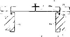
Figure 12 is the section-drawing of taking advantage of mouthful door gear one example of the traditional elevator of expression, and Figure 13 is the section-drawing along the XIII-XIII line of Figure 12.
Among the figure, building take advantage of mouthful wall 1 to be provided with to take advantage of mouthful gangway 2.This takes advantage of mouthful gangway 2 to be formed by three squares bearer 3 as frame body.Three squares bearer 3 have the vertical framework 4a of 1 couple, the 4b of vertical configuration extension and are arranged between the top of indulging framework 4a, 4b and the upper frame 4c of horizontal extension.Be fixed with the vertical framework fireproof component 6 of section L word shape in the end of elevating road 5 sides of indulging framework 4a, 4b.
Take advantage of mouthful gangway 2 to take advantage of the door 7 of mouth to open and close by 1 pair.When the door of the door of respectively taking advantage of mouthful 7 is opened side end and is fixed with door and closes and the reveal portion fireproof component 8 of vertical framework fireproof component 6 subtends.Vertical framework fireproof component 6 and reveal portion fireproof component 8 extend along whole above-below direction (above-below direction of Figure 13) vertical configuration of the door 7 of taking advantage of mouth.
Be fixed with the upper frame fireproof component 9 of the section L word shape of horizontal extension at elevating road 5 side ends of upper frame 4c.When being fixed with door in the upper end of the door of respectively taking advantage of mouthful 7 and closing with a top fireproof component 10 of upper frame fireproof component 9 subtends.
Be provided with in the floor portion of taking advantage of mouthful gangway 2 and take advantage of mouthful threshold 11.Be provided with the pin 12 that the door in mouthful threshold 11 is taken advantage of in insertion in the bottom of the door 7 of respectively taking advantage of mouth.
Take advantage of in mouthful door gear this, having reveal portion fireproof component 8 is so-called weak mutually power (phase ぃ ャ く リ) structure with vertical framework fireproof component 6 subtends, door top fireproof component 10 with the structure of upper frame fireproof component 9 subtends.In case because of fire makes the door of taking advantage of mouthful 7 deflections take place, then reveal portion fireproof component 8 engage with vertical framework fireproof component 6, a door top fireproof component 10 engages with upper frame fireproof component 9, can prevent to take advantage of 7 of mouth to deviate from.Adopt this structure, can obtain necessary fire resistance.
But above-mentioned fireproof construction is applicable to mouthful door gear of newly establishing of taking advantage of, and in order to be applicable to the existing mouthful door gear of taking advantage of, must change all three squares bearer 3 and the door 7 taken advantage of mouthful maybe need be implemented to append on a large scale engineering is set, and has not only bothered but also changes the expense cost.Even be applicable to the occasion of newly establishing elevator,, also need change expense the time of adjusting is installed because of fireproof component 8 is long chi shapes again.
Summary of the invention
The present invention is in order to address the above problem, and its purpose is to provide a kind of mouthful door gear of taking advantage of of the elevator that appends fireproof construction at the Men Shangke that takes advantage of mouthful easily.
Elevator of the present invention take advantage of a mouthful door gear, comprising: have the vertical framework that vertical configuration extends and be formed with the frame body of taking advantage of mouthful gangway, and taking advantage of mouthful door of taking advantage of that mouthful gangway opens and closes; It is characterized in that, open the top local configuration of side end and be fixed with door when closing and the fireproof component of vertical framework subtend at the door of the door of taking advantage of mouthful, either party in vertical framework and fireproof component is provided with porose, the opposing party at vertical framework and fireproof component is provided with the insertion section, this insertion section inserts in the hole when door closes, and restriction takes advantage of the door of mouth to be out of shape to the lifting trackside.
Again, elevator of the present invention take advantage of a mouthful door gear, comprising: have the vertical framework that vertical configuration extends and be formed with the frame body of taking advantage of mouthful gangway, and taking advantage of mouthful door of taking advantage of that mouthful gangway opens and closes; It is characterized in that, open the top local configuration of side end and be fixed with door fireproof component at the door of the door of taking advantage of mouthful with the 1st subtend face that the switching direction parallel shape with the door of taking advantage of mouthful extends, on vertical framework, be fixed with stationary member, and vertical framework fireproof component is installed by stationary member, vertical framework fireproof component has the 2nd subtend face, limits a distortion to the lifting trackside of taking advantage of mouth by making the 1st subtend face and the 2nd subtend face be subtend when door closes.
The simple declaration of accompanying drawing
Fig. 1 is the section-drawing of taking advantage of mouthful door gear of the elevator of the expression embodiment of the invention 1.
Fig. 2 is the block diagram of wanting portion of presentation graphs 1.
Fig. 3 is the section-drawing of taking advantage of mouthful door gear of the elevator of the expression embodiment of the invention 2.
Fig. 4 is the block diagram of wanting portion of presentation graphs 3.
Fig. 5 is the section-drawing of taking advantage of mouthful door gear of the elevator of the expression embodiment of the invention 3.
Fig. 6 is the block diagram of wanting portion of presentation graphs 6.
Fig. 7 is the section-drawing of taking advantage of mouthful door gear of the elevator of the expression embodiment of the invention 4.
Fig. 8 is the block diagram of wanting portion of presentation graphs 7.
Fig. 9 is the section-drawing of taking advantage of mouthful door gear of the elevator of the expression embodiment of the invention 5.
Figure 10 is the block diagram of wanting portion of presentation graphs 9.
Figure 11 is the exploded perspective view of expression Figure 10 and vertical framework and vertical framework fireproof component.
Figure 12 is the section-drawing of taking advantage of mouthful door gear one example of the traditional elevator of expression.
Figure 13 is the section-drawing along the XIII-XIII line of Figure 12.
The specific embodiment
Preferred embodiment of the present invention is described with reference to the accompanying drawings.
Embodiment 1
Fig. 1 is the section-drawing of taking advantage of mouthful door gear of the elevator of the expression embodiment of the invention 1, and Fig. 2 is the block diagram of wanting portion of presentation graphs 1.Among the figure, building take advantage of mouthful wall 1 to be provided with to take advantage of mouthful gangway 2.This takes advantage of mouthful gangway 2 to be formed by three squares bearer 3 as frame body.Three squares bearer 3 have the vertical framework 4a of 1 couple, the 4b of vertical configuration extension and are arranged between the top of indulging framework 4a, 4b and the upper frame 4c (Figure 13) of horizontal extension.Near the upper end of vertical framework 4a, 4b, be provided with hole 21.
Take advantage of mouthful gangway 2 to take advantage of the door 7 of mouth to open and close by 1 pair.When being fixed with door on the top that the door of the door of respectively taking advantage of mouthful 7 is opened side end and closing and the flat fireproof component 21 of vertical framework 4a, 4b subtend.Be pin 23 by being welded with the insertion section on fireproof component 22, this pin 23 is when door closes in the patchhole 21, and door that restriction is taken advantage of mouthful 7 is out of shape to the lifting trackside.Can use bolt etc. as pin 23.
The same with Figure 13, be provided with in the floor portion of taking advantage of mouthful gangway 2 and take advantage of mouthful threshold 11.Be provided with the pin 12 that the door in mouthful threshold 11 is taken advantage of in insertion in the bottom of the door 7 of respectively taking advantage of mouth.
Between the diameter of the diameter in hole 21 and pin 23, preferably leave surplus to a certain degree.Can absorb 7 becomes flexible of taking advantage of mouth thus, can be when door closes more reliably with in pin 23 patchholes 21.
Adopt this mouthful door gear of taking advantage of, because door is when closing in pin 23 patchholes 21, so even also can limit door 7 distortion of taking advantage of mouthful to elevating road 5 sides when heating because of fire, what can prevent to take advantage of mouthful 7 deviates from, and can prevent that flame and cigarette from flowing in elevating road 5.Again because fireproof component 22 door of the door 7 taken advantage of mouthful of local configuration and the being fixed on top of opening side end just, and, on vertical framework 4a, 4b, only hole 21 need be set and get final product, therefore newly establish and established take advantage of mouth 7 on can easily append fireproof construction.
At this, because of being inserted in, takes advantage of in mouthful threshold 11 on the pin 12 of door, so when even the door of taking advantage of mouthful 7 heats because of fire, the bottom of the door of taking advantage of mouthful 7 also is accurate stationary state.Comparatively speaking, the upper end of the door of taking advantage of mouthful 7 is because of being to be hung structure down by gantry crane hook (not shown), thus in case take advantage of 7 of mouth to be out of shape, then and the gap of 3 of three squares bearer can become big.
Yet, in embodiment 1, because porose 21, fireproof component 22 and pin 23 are set near the upper end of the door of taking advantage of mouthful 7, therefore, the gap that door 7 and three squares bearer that can prevent from effectively to take advantage of mouthful are 3.That is, can not guarantee sufficient fire resistance even be not provided with across the fireproof construction of the whole above-below direction of the door of taking advantage of mouthful 7 yet.
Taking advantage of in mouthful door gear of embodiment 1,, therefore can restrain the increase of door 7 weight of taking advantage of mouth because fireproof component 22 is a local part that is installed in the above-below direction of the door 7 of taking advantage of mouth again.
Last example is that pin 23 is welded on the fireproof component 21, but the fixing means of insertion member is not limited to this.
Again, the shape in hole can be carried out various changes according to the section shape that inserts member, and is both square, also the hole can be made the slotted hole that above-below direction extends.
And the quantity of hole and insertion member is not particularly limited, and for example also a plurality of insertion members can be inserted in 1 slotted hole simultaneously.
Fig. 3 is the section-drawing of taking advantage of mouthful door gear of the elevator of the expression embodiment of the invention 2, and Fig. 4 is the block diagram of wanting portion of presentation graphs 3.
Among the figure, near the upper end of vertical framework 4a, 4b, be provided with a plurality of joint-cuttings 24 as the hole.When being fixed with door on the top that the door of the door of respectively taking advantage of mouthful 7 is opened side end and closing and the flat fireproof component 25 of vertical framework 4a, 4b subtend.
Being provided with the insertion section in the end of fireproof component 25 is joggling part 25a, and this joggling part 25a inserts when door closes in the joint-cutting 24, and door 7 distortion to lifting trackside 5 of mouth are taken advantage of in restriction.Joggling part 25a forms a part of warpage of fireproof component 25.Other structure is identical with embodiment 1.
Adopt this mouthful door gear of taking advantage of and since door when closing joggling part 25a insert in the joint-cutting 24, so even also can limit door 7 distortion of taking advantage of mouthful to elevating road 5 sides when heating because of fire, what can prevent to take advantage of mouthful 7 deviates from, and can prevent that flame and cigarette from flowing in elevating road 5.Again because fireproof component 25 door of the door 7 taken advantage of mouthful of local configuration and the being fixed on top of opening side end just, and on vertical framework 4a, 4b, only joint-cutting 24 need be set and get final product, therefore newly establish and established take advantage of mouth 7 on can easily append fireproof construction.
And,,, can further facilitate in installation so can reduce the part number because of joggling part 25a and fireproof component 25 are wholely set.
Fig. 5 is the section-drawing of taking advantage of mouthful door gear of the elevator of the expression embodiment of the invention 3, and Fig. 6 is the block diagram of wanting portion of presentation graphs 5.In this example, be that pin 26 is fixed near the upper end of vertical framework 4a, 4b with the insertion section by welding.When being fixed with door on the top that the door of the door of respectively taking advantage of mouthful 7 is opened side end and closing and the flat fireproof component 25 of vertical framework 4a, 4b subtend.Fireproof component 27 is provided with the hole 27a that can insert pin 26 when door closes.
Adopt this mouthful door gear of taking advantage of, because door is when closing among the pin 26 patchhole 27a, so can limit 7 a distortion of taking advantage of mouthful to elevating road 5 sides.That is, opposite with embodiment 1, on vertical framework 4a, 4b, pin 26 is set, hole 27a is set on fireproof component 27, this occasion also can obtain the effect identical with embodiment 1.
Embodiment 4
Fig. 7 is the section-drawing of taking advantage of mouthful door gear of the elevator of the expression embodiment of the invention 4, and Fig. 8 is the block diagram of wanting portion of presentation graphs 7.Fixing on the top that the door of the door of respectively taking advantage of mouthful 7 is opened side end and to have the fireproof component 33 that opens and closes the 1st subtend face 33a that direction (left and right directions of Fig. 7) parallel shapes extend with the door of taking advantage of mouthful 7.
Indulging on framework 4a, the 4b by being welded with clip 32 as stationary member.Clamping has the vertical framework fireproof component 31 of section L word shape between clip 32 and vertical framework 4a, 4b.Vertical framework fireproof component 31 has the 2nd subtend face 31a parallel with the 1st subtend face 33a.
When framework fireproof component 31 is indulged in installation, at first clip 32 is fixed on vertical framework 4a, the 4b, will indulge framework fireproof component 31 then and push between clip 32 and vertical framework 4a, the 4b.Leading section at clip 32 is provided with pawl, and vertical framework fireproof component 31 is provided with the groove that inserts pawl.
Door is when closing, by 7 distortion to elevating road 5 sides that the 1st subtend face 33a and the 2nd subtend face 31a subtend is limited take advantage of mouthful.That is, fireproof component 33 has the part that is flexed into U groove shape, and when door closed, the part of vertical framework fireproof component 31 was inserted in the U groove.Other structure is identical with embodiment 1.
Adopt this mouthful door gear of taking advantage of, because the 1st subtend face 33a and the 2nd subtend face 31a were subtend when door closed, even event also can limit door 7 distortion to elevating road 5 sides of taking advantage of mouth when heating because of fire, can prevent to take advantage of the door 7 of mouth to deviate from, and can prevent that flame and cigarette from flowing in elevating road 5.Again because door fireproof component 33 and vertical framework the fireproof component 31 just door 7 taken advantage of mouthful of local configuration and being fixed on and the top of vertical framework 4a, 4b, and on vertical framework 4a, 4b, only need fixedly clip 32, to indulge framework fireproof component 31 and push and get final product, therefore on the door of taking advantage of mouthful 7 of newly establishing and having established, can easily append fireproof construction.
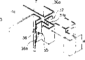
Fig. 8 is the section-drawing of taking advantage of mouthful door gear of the elevator of the expression embodiment of the invention 5, and Fig. 9 is the block diagram of wanting portion of presentation graphs 8.Fixing on the top that the door of the door of respectively taking advantage of mouthful 7 is opened side end and to have the fireproof component 37 that opens and closes the 1st subtend face 37a that direction (left and right directions of Fig. 9) parallel shapes extend with the door of taking advantage of mouthful 7.
On vertical framework 4a, 4b, fixing hook 35 as stationary member by welding.The vertical framework fireproof component 36 of section L word shape is installed by hook 35 on vertical framework 4a, 4b.Vertical framework fireproof component 36 has the 2nd subtend face 36a parallel with the 1st subtend face 37a and can insert the hole 36b of logical hook 35.For example bolt can be used as hook 35, for example circular hole can be used as hole 36b.Figure 11 is the exploded perspective view of expression Figure 10 and vertical framework 4a, 4b and vertical framework fireproof component 36.
When door closes, by making the 1st subtend face 37a and the 2nd subtend face 36a subtend, can limit door 7 the distortion of taking advantage of mouth to elevating road 5 sides.That is, fireproof component 37 has the part that is flexed into U groove shape, and when door closed, the part of vertical framework fireproof component 36 was inserted in the U groove.Other structure is identical with embodiment 1.
Adopt this mouthful door gear of taking advantage of, because the 1st subtend face 37a and the 2nd subtend face 36a were subtend when door closed, even event also can limit door 7 distortion to elevating road 5 sides of taking advantage of mouth when heating because of fire, can prevent to take advantage of the door 7 of mouth to deviate from, and can prevent that flame and cigarette from flowing in elevating road 5.Again because door fireproof component 37 and vertical framework the fireproof component 36 just door 7 taken advantage of mouthful of local configuration and being fixed on and the top of vertical framework 4a, 4b, and on vertical framework 4a, 4b, only need fixedly clip 35, to indulge framework fireproof component 36 cards and only get final product, therefore on the door 7 of taking advantage of mouth of newly establishing and having established, can easily append fireproof construction.
Only be provided with 1 clip 35 in the last example, but the clip 35 more than 2 or 2 also can be set.Again, the quantity of hole 36b should be corresponding with clip 35, also more than 2 or 2.
Wherein, even sufficient fire resistance also can be guaranteed in below 1/3 or 1/3 of the size up and down of the door 7 that the H of size up and down of the fireproof component 22,25,27,33,37 of door 7 sides of taking advantage of mouthful in the foregoing description 1~5 takes advantage of mouthful.That is, take advantage of in the scope below 1/3 or 1/3 of size up and down of mouthful gangway 2, also can guarantee sufficient fire resistance even fireproof component 22,25,27,33,37 only is arranged on from the upper end of taking advantage of mouthful gangway 2.
In the experiment,, fireproof component 22,25,27,33,37 (takes advantage of the size up and down of mouthful gangway 2: 2200mm even only being arranged on 1/10 or 1/10 following scope of the size up and down of taking advantage of mouthful gangway 2 from the upper end of taking advantage of mouthful gangway 2; The size up and down of fireproof component: 200mm), also can guarantee sufficient fire resistance.
Claims (7)
- An elevator take advantage of a mouthful door gear, comprising:Have the vertical framework of vertical configuration extension and be formed with the frame body of taking advantage of mouthful gangway, andTo taking advantage of mouthful door of taking advantage of that mouthful gangway opens and closes;It is characterized in that,Open the top local configuration of side end and be fixed with door when closing and the fireproof component of described vertical framework subtend at the door of the described door of taking advantage of mouthful,Either party in described vertical framework and described fireproof component is provided with porose,The opposing party at described vertical framework and described fireproof component is provided with the insertion section, and insert when door closes in the described hole this insertion section, limits the described door of mouth of taking advantage of and is out of shape to the lifting trackside.
- Elevator as claimed in claim 1 take advantage of a mouthful door gear, it is characterized in that described fireproof component is configured in the scope below 1/3 or 1/3 of the described size up and down of taking advantage of mouthful gangway in described upper end of taking advantage of mouthful gangway.
- Elevator as claimed in claim 1 take advantage of a mouthful door gear, it is characterized in that described insertion section forms by a part of warpage with fireproof component.
- An elevator take advantage of a mouthful door gear, comprising:Have the vertical framework of vertical configuration extension and be formed with the frame body of taking advantage of mouthful gangway, andTo taking advantage of mouthful door of taking advantage of that mouthful gangway opens and closes;It is characterized in that,Open the top local configuration of side end and be fixed with door fireproof component at the door of the described door of taking advantage of mouthful with the 1st subtend face that the switching direction parallel shape with the described door of taking advantage of mouthful extends,On described vertical framework, be fixed with stationary member, and vertical framework fireproof component be installed by described stationary member,Described vertical framework fireproof component has the 2nd subtend face,By when door closes, making described the 1st subtend face and described the 2nd subtend face limit the described door of taking advantage of mouthful and be out of shape to the lifting trackside through being subtend.
- Elevator as claimed in claim 4 take advantage of a mouthful door gear, it is characterized in that described stationary member is a clip, described vertical framework fireproof component is clamped between described clip and the described vertical framework.
- Elevator as claimed in claim 4 take advantage of a mouthful door gear, it is characterized in that described stationary member is a hook, described vertical framework fireproof component is provided with the hole that can insert described hook.
- 7. elevator as claimed in claim 1 takes advantage of a mouthful door gear, it is characterized in that described door fireproof component and described vertical framework fireproof component are configured in the scope below 1/3 or 1/3 of the described size up and down of taking advantage of mouthful gangway in described upper end of taking advantage of mouthful gangway.
Applications Claiming Priority (1)
| Application Number | Priority Date | Filing Date | Title |
|---|---|---|---|
| PCT/JP2002/003774 WO2003086938A1 (en) | 2002-04-16 | 2002-04-16 | Landing stage door of elevator |
Publications (1)
| Publication Number | Publication Date |
|---|---|
| CN1514800A true CN1514800A (en) | 2004-07-21 |
Family
ID=29227593
Family Applications (1)
| Application Number | Title | Priority Date | Filing Date |
|---|---|---|---|
| CNA028115651A Pending CN1514800A (en) | 2002-04-16 | 2002-04-16 | Landing stage door device of elevator |
Country Status (4)
| Country | Link |
|---|---|
| EP (1) | EP1496005A1 (en) |
| JP (1) | JP4158911B2 (en) |
| CN (1) | CN1514800A (en) |
| WO (1) | WO2003086938A1 (en) |
Cited By (2)
| Publication number | Priority date | Publication date | Assignee | Title |
|---|---|---|---|---|
| CN102153010A (en) * | 2010-02-12 | 2011-08-17 | 东芝电梯株式会社 | Storey-standing door device |
| CN113666219A (en) * | 2020-05-15 | 2021-11-19 | 株式会社日立制作所 | Elevator and landing door |
Families Citing this family (8)
| Publication number | Priority date | Publication date | Assignee | Title |
|---|---|---|---|---|
| JP2005320121A (en) * | 2004-05-10 | 2005-11-17 | Mitsubishi Electric Corp | Landing door device for elevator |
| JP2010137957A (en) * | 2008-12-11 | 2010-06-24 | Toshiba Elevator Co Ltd | Doorway device for elevator and renewal method for doorway device for elevator |
| KR101206703B1 (en) * | 2010-10-07 | 2012-11-29 | 오티스 엘리베이터 컴파니 | Structure for blocking flame of elevator fire door |
| JP5941291B2 (en) * | 2012-02-10 | 2016-06-29 | 株式会社Lixil | sash |
| KR101351071B1 (en) | 2013-07-16 | 2014-01-15 | (주)대원엔지니어링 | Elevator four-door assembly with fireproof construction |
| CN105819317B (en) * | 2016-05-19 | 2018-04-10 | 江南嘉捷电梯股份有限公司 | A kind of elevator antetheca door gap sealing structure |
| WO2020115811A1 (en) * | 2018-12-04 | 2020-06-11 | 株式会社日立製作所 | Elevator |
| JP6903780B1 (en) * | 2020-03-06 | 2021-07-14 | 東芝エレベータ株式会社 | Three-sided frame closing plate installation member, closing plate installation structure and closing plate installation method |
Family Cites Families (3)
| Publication number | Priority date | Publication date | Assignee | Title |
|---|---|---|---|---|
| JP3816215B2 (en) * | 1997-10-28 | 2006-08-30 | 三菱電機株式会社 | Elevator door equipment |
| JP3538096B2 (en) * | 2000-01-12 | 2004-06-14 | 三菱電機株式会社 | Elevator landing door |
| JP2003012258A (en) * | 2001-07-05 | 2003-01-15 | Mitsubishi Electric Corp | Sliding door device for elevator landing |
-
2002
- 2002-04-16 JP JP2003583909A patent/JP4158911B2/en not_active Expired - Fee Related
- 2002-04-16 CN CNA028115651A patent/CN1514800A/en active Pending
- 2002-04-16 WO PCT/JP2002/003774 patent/WO2003086938A1/en not_active Application Discontinuation
- 2002-04-16 EP EP02717176A patent/EP1496005A1/en not_active Withdrawn
Cited By (2)
| Publication number | Priority date | Publication date | Assignee | Title |
|---|---|---|---|---|
| CN102153010A (en) * | 2010-02-12 | 2011-08-17 | 东芝电梯株式会社 | Storey-standing door device |
| CN113666219A (en) * | 2020-05-15 | 2021-11-19 | 株式会社日立制作所 | Elevator and landing door |
Also Published As
| Publication number | Publication date |
|---|---|
| EP1496005A1 (en) | 2005-01-12 |
| JP4158911B2 (en) | 2008-10-01 |
| JPWO2003086938A1 (en) | 2005-08-18 |
| WO2003086938A1 (en) | 2003-10-23 |
Similar Documents
| Publication | Publication Date | Title |
|---|---|---|
| CN1514800A (en) | Landing stage door device of elevator | |
| CN1266404C (en) | Chucking | |
| BR0005921A (en) | Elevator shaft | |
| CN201587780U (en) | Traveling cable for elevator | |
| CN201301152Y (en) | Three-door elevator car | |
| CN205542857U (en) | Dual -glass photovoltaic assembly installs briquetting | |
| CN205557918U (en) | Section bar fast -assembling mechanism | |
| CN1437556A (en) | Car upper handrail device of elevator | |
| CN209906135U (en) | Assembly type elevator shaft | |
| CN210660143U (en) | Support frame for coal mine safety production | |
| CN211037382U (en) | Fireproof wallboard of integrated house | |
| CN203021145U (en) | Household elevator sedan with double doors in mutually perpendicular directions | |
| CN109210447B (en) | LED ceiling lamp | |
| CN217107858U (en) | Novel plastic end cover | |
| CN213020992U (en) | Furnace door opening and closing structure | |
| CN208200092U (en) | A kind of elevator symmetrical structure narrow door jamb | |
| CN217600241U (en) | A spacing guide arm structure for hoist | |
| CN2868473Y (en) | Linkage dual regulating door mechanism for smoke discharge cabinet | |
| CN211447849U (en) | Auxiliary device is hung to advance outer wall clamp of window that wafts in area | |
| CN217296848U (en) | Right-angle double-door elevator | |
| CN216893946U (en) | Simple hanging structure of sliding door | |
| CN212201003U (en) | High strength building steel structure | |
| CN217054784U (en) | Sliding rail structure of lifting window | |
| CN206553041U (en) | A kind of novel elevator door-plate slider bracket and its sliding block | |
| CN211342596U (en) | Fireproof window sash convenient to install |
Legal Events
| Date | Code | Title | Description |
|---|---|---|---|
| C06 | Publication | ||
| PB01 | Publication | ||
| C10 | Entry into substantive examination | ||
| SE01 | Entry into force of request for substantive examination | ||
| C02 | Deemed withdrawal of patent application after publication (patent law 2001) | ||
| WD01 | Invention patent application deemed withdrawn after publication |