CN1493893A - Magnification optical fiber and its preparation method - Google Patents
Magnification optical fiber and its preparation method Download PDFInfo
- Publication number
- CN1493893A CN1493893A CNA031553923A CN03155392A CN1493893A CN 1493893 A CN1493893 A CN 1493893A CN A031553923 A CNA031553923 A CN A031553923A CN 03155392 A CN03155392 A CN 03155392A CN 1493893 A CN1493893 A CN 1493893A
- Authority
- CN
- China
- Prior art keywords
- amplifying fiber
- mol
- fiber according
- covering
- amplifying
- Prior art date
- Legal status (The legal status is an assumption and is not a legal conclusion. Google has not performed a legal analysis and makes no representation as to the accuracy of the status listed.)
- Pending
Links
Images


Classifications
-
- G—PHYSICS
- G02—OPTICS
- G02B—OPTICAL ELEMENTS, SYSTEMS OR APPARATUS
- G02B6/00—Light guides; Structural details of arrangements comprising light guides and other optical elements, e.g. couplings
- G02B6/02—Optical fibres with cladding with or without a coating
-
- H—ELECTRICITY
- H01—ELECTRIC ELEMENTS
- H01S—DEVICES USING THE PROCESS OF LIGHT AMPLIFICATION BY STIMULATED EMISSION OF RADIATION [LASER] TO AMPLIFY OR GENERATE LIGHT; DEVICES USING STIMULATED EMISSION OF ELECTROMAGNETIC RADIATION IN WAVE RANGES OTHER THAN OPTICAL
- H01S3/00—Lasers, i.e. devices using stimulated emission of electromagnetic radiation in the infrared, visible or ultraviolet wave range
- H01S3/05—Construction or shape of optical resonators; Accommodation of active medium therein; Shape of active medium
- H01S3/06—Construction or shape of active medium
- H01S3/063—Waveguide lasers, i.e. whereby the dimensions of the waveguide are of the order of the light wavelength
- H01S3/067—Fibre lasers
- H01S3/06708—Constructional details of the fibre, e.g. compositions, cross-section, shape or tapering
-
- C—CHEMISTRY; METALLURGY
- C03—GLASS; MINERAL OR SLAG WOOL
- C03C—CHEMICAL COMPOSITION OF GLASSES, GLAZES OR VITREOUS ENAMELS; SURFACE TREATMENT OF GLASS; SURFACE TREATMENT OF FIBRES OR FILAMENTS MADE FROM GLASS, MINERALS OR SLAGS; JOINING GLASS TO GLASS OR OTHER MATERIALS
- C03C13/00—Fibre or filament compositions
- C03C13/04—Fibre optics, e.g. core and clad fibre compositions
- C03C13/041—Non-oxide glass compositions
- C03C13/043—Chalcogenide glass compositions
- C03C13/044—Chalcogenide glass compositions containing halogen, e.g. chalcohalide glass compositions
-
- C—CHEMISTRY; METALLURGY
- C03—GLASS; MINERAL OR SLAG WOOL
- C03C—CHEMICAL COMPOSITION OF GLASSES, GLAZES OR VITREOUS ENAMELS; SURFACE TREATMENT OF GLASS; SURFACE TREATMENT OF FIBRES OR FILAMENTS MADE FROM GLASS, MINERALS OR SLAGS; JOINING GLASS TO GLASS OR OTHER MATERIALS
- C03C13/00—Fibre or filament compositions
- C03C13/04—Fibre optics, e.g. core and clad fibre compositions
- C03C13/045—Silica-containing oxide glass compositions
- C03C13/046—Multicomponent glass compositions
Abstract
The amplifying optical fiber is located in the center of an optical fiber and comprised of an internal core which contains MX, GaS<SB>3/2</SB>and RE, an external core which surrounds the internal core and contains SiO<SB>2</SB>and a clad which surrounds the external core and contains SiO<SB>2</SB>. M which composes MX is a component selected from the group consisting of Na, K, Rb and Cs. X which composes MX is a component selected from the group consisting of F, Cl, Br and I. RE is a component selected from the group consisting of Ce, Pr, Pm, Nd, Sm, Eu, Gd, Tb, Ho, Dy, Er, Tm and Yb.
Description
Technical field
The present invention relates to optical fiber, and more specifically, relate to amplifying fiber and preparation method thereof.
Background technology
For the rare earth element of trivalent ion attitude such as Ce, Pr, Nd, Pm, Sm, Eu, Gd, Tb, Dy, Ho, Er, Tm and Yb can be by electronic transition emitting fluorescence.The optical fiber that contains these rare earth element can possess the function of the light signal amplification that will import with the method for stimulated emission effect.If the reflectivity to the optical fiber two ends is suitably adjusted, this optical fiber can also possess the function of the optical-fiber laser that produces stimulated emission constantly.Typically, in the frequency span of optical communication, Pr
3+, Nd
3+And Dy
3+In wavelength coverage is 1.3 to 1.4 μ m emitting fluorescences, Tm
3+In wavelength coverage is 1.4 to 1.5 μ m emitting fluorescences, and Er
3+In wavelength coverage is 1.5 to 1.6 μ m emitting fluorescences.Therefore, be doped with Er
3+Fiber amplifier in wavelength is the frequency span of optical communication of 1.5 to 1.6 μ m, be widely used.
In wavelength coverage is 1.5 to 1.6 μ m, use be by with Er
3+Be added in the quartz glass optical fiber commonly used and preparation be doped with Er
3+Fiber amplifier.But, owing to be 1.3 to 1.4 μ m or 1.4 to 1.5 μ m in wavelength coverage, Pr
3+, Dy
3+And Tm
3+The efficient of emitting fluorescence is too low in quartz glass, so be used for not dropping into practical application usually at the fiber amplifier of this wavelength coverage emitting fluorescence.As the alternatives of avoiding these problems, denomination of invention is the U.S.P5 that is presented to Kazuo Fuziura of " Process for thepreparation of fluoride glass and process for the preparation of optical fiberperform using the fluoride glass ", 071,460, with the U.S.P that be presented to Lubos Vacha 5 of denomination of invention for " Polyimide coated heavy metal fluoride glass fiberand method of manufacture ", 567,219, disclose a kind of method for preparing amplifying fiber, this method is by joining rare earth element in the fluoride glass optical fiber so that improve fluorescent emission efficient.
But be to use the problem of fluoride glass below taking place: fluoride glass is different from existing quartz glass, and it can not be with the chemical deposition highly purified basic glass material of having got everything ready, and is difficult to the refringence between core and covering is controlled in 0.1% the scope.As the alternatives of this problem, disclose a kind of by using method to prepare the method for fluoridizing amplifying fiber at surface dress sheath.
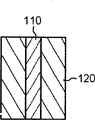
Fig. 1 and 2 illustrates known the passing through of prior art and uses the method that coats sheath to prepare the method for fluoridizing amplifying fiber.With reference to Fig. 1 and 2, with of the form preparation of the corresponding part of amplifying fiber core with rod 110, and with the corresponding other parts of its covering to manage 120 form preparation.Rod 110 is inserted in the hole 125 that forms in pipe 120, prepares stock with form with rod.Then, fluoridize the stretcher of amplifying fiber, will fluoridize optical fiber and stretch by use.
On the other hand, be presented to the U.S.P 6 of the denomination of invention of Polly Wanda Chu for " Composition foroptical waveguide article and method of making continuous clad filament ", 128,430 and denomination of invention be the U.S.P 6 of " Method of making an optical fiber by meltingparticulate glass in a glass cladding tube ", 374,641, a kind of step of in the quartz ampoule quartz glass composition being fluoridized that is included in is disclosed, in other words, will substitute so that improve the preparation method with fluoride as the quartz of core composition.
Fig. 3 illustrate prior art known fluoridize amplifying fiber figure.Fluoridize amplifying fiber 200 and comprise core 210 that places fiber optic hub and the covering 220 that centers on core 210.As understandable, because therefore the problem that light signal transmits in multimode 240,250 has taken place the quite tangible refringence of core 210 and 220 existence of covering from refractive index distribution curve 230.If will fluoridize the core diameter A of amplifying fiber 200 reduces to below the 4 μ m in order to transmit light signal in single mode, so when fluoridizing amplifying fiber and be connected with quartzy amplifying fiber, connecting loss increases quite obviously, and the diameter of representational silica fibre is 8 μ m.
As mentioned above, the known amplifying fiber of prior art comprises the problem of listing below.
At first, when transmitting by the amplifying fiber that has the index of refraction difference between core and covering, light wave transmits with multimode.
Secondly, reduce to below the 4 μ m if will fluoridize the core diameter of amplifying fiber, when fluoridizing the silica fibre of amplifying fiber with transmission light and is connected, connecting to lose has quite significantly increase.
The 3rd, when fluoride glass is exposed in the humidity, because O-H chemical bond in fluoride glass increases, so the light wave loss increases and the physical strength of optical fiber reduces, and thereby the reliability deterioration of amplifying fiber.
The 4th, when substituting quartz glass, produce the obvious problem that increases of light scattering loss that becomes branch to cause because of oxidation-fluoride core with fluoride glass.
Summary of the invention
The invention provides a kind of is that 8 μ m make the amplifying fiber that connects minimization of loss and transmit light with single mode by the holding core diameter.
Even it is a kind of when amplifying fiber is placed wet environment that one embodiment of the invention provide, the amplifying fiber that the light wave loss does not also increase and physical strength is kept.
One embodiment of the invention provide a kind of amplifying fiber that improves fluorescent emission efficient and light amplification efficient.
One embodiment of the invention provide a kind of amplifying fiber, and the optical dispersion loss is reduced in this amplifying fiber.
One embodiment of the invention provide a kind of method that is used to prepare the amplifying fiber that achieves the above object.
The invention provides a kind of amplifying fiber that is used for amplifying optical signals, this light signal transmits by amplifying fiber with stimulated emission, and this amplifying fiber comprises: place the center of described optical fiber and contain MX, GaS
3/2Inner core with RE; Center on described inner core and contain SiO
2Outer core; With around described outer core and contain SiO
2Covering, the M among the wherein said MX of being contained in is a kind of composition that is selected among Na, K, Rb and the Cs; X among the described MX of being contained in is a kind of composition that is selected among F, Cl, Br and the I; With described RE be a kind of composition that is selected among Ce, Pr, Pm, Nd, Sm, Eu, Gd, Tb, Ho, Dy, Er, Tm and the Yb.
Description of drawings
Fig. 1 and Fig. 2 illustrate and adopt the method that coats sheath to prepare the conventional method of fluoridizing amplifying fiber;
Fig. 3 illustrates the conventional amplifying fiber of fluoridizing;
Fig. 4 diagram is according to amplifying fiber of the present invention;
Fig. 5 to 9 is method key diagrams of the present invention's stock of preparing amplifying fiber;
Figure 10 illustrates a kind of structure of light amplification gain measurement equipment; With
Figure 11 diagram is used in the light amplification gain spectra that measuring equipment shown in Figure 10 is measured.
Embodiment
Below, embodiment with reference to the accompanying drawings to describe the present invention.For clear and simple purpose,, will omit it will be described in detail when the known function and the detailed description of structure when theme of the present invention is not known a little incorporated into wherein.
What Fig. 4 showed is a kind of amplifying fiber of the present invention.Amplifying fiber 300 comprises: the inner core 310 that places described amplifying fiber 300 centers; Around the outer core 320 of described inner core 310 with around the covering of described outer core 320.
The diameter C of inner core is 0.1 to 8 μ m and can contains 5 to 67mol% MX, 5 to 50mol% GaS
3/2With 0.001 to 5mol% RE.In addition, it can also comprise one of following: greater than 0 and be less than or equal to the Ge of 33mol%, greater than 0 and be less than or equal to the As of 40mol%, greater than 0 and be less than or equal to the S of 67mol% and greater than 0 and be less than or equal to the LaS of 50mol%
3/2The M that contains in described MX can be a kind of composition that is selected among Na, K, Rb and the Cs; The X that contains in described MX can be a kind of composition that is selected among F, Cl, Br and the I.In addition, RE is a kind of rare earth element and can is a kind of composition that is selected among Ce, Pr, Pm, Nd, Sm, Eu, Gd, Tb, Ho, Dy, Er, Tm and the Yb.
The diameter D of outer core 320 is 2 to 10 μ m and can contains 30 to 100mol% SiO
2In addition, it can also comprise one of following: greater than 0 and be less than or equal to the B of 30mol%
2O
3, greater than 0 and be less than or equal to the P of 10mol%
2O
5, greater than 0 and be less than or equal to the Al of 10mol%
2O
3, greater than 0 and be less than or equal to the GeO of 30mol%
2, greater than 0 and be less than or equal to the PbO of 40mol% and greater than 0 and be less than or equal to the SiF of 10mol%
4
The diameter E of covering 330 is 100 to 250 μ m and can contains 30 to 100mol% SiO
2In addition, it can also comprise one of following: greater than 0 and be less than or equal to the B of 30mol%
2O
3, greater than 0 and be less than or equal to the P of 10mol%
2O
5, greater than 0 and be less than or equal to the Al of 10mol%
2O
3, greater than 0 and be less than or equal to the GeO of 30mol%
2, greater than 0 and be less than or equal to the PbO of 40mol% and greater than 0 and be less than or equal to the SiF of 10mol%
4Outer core 320 and 330 refractive indices n of covering are based upon in 0.001 to 10% the scope and are preferably below 2%.Perhaps, 320 refractive indices n of inner core 310 and outer core are set to below 2%.In the case, the diameter C with inner core 310 is arranged in the scope of 1 to 8 μ m.
Fig. 5 to 9 is method key diagrams of the present invention's stock of preparing amplifying fiber.It is as follows that preparation is used for the step that the method for stock of amplifying fiber comprises: forms outer core, supplies raw material, the formation inner core with split pipe.
The step that forms outer core is the process with method core 430 outside the inwall of the quartz ampoule 420 that is used for covering forms of chemical vapor deposition.With reference to figure 5, use the outer wall heating of thermal source such as oxygen/hydrogen burner with quartz ampoule 420, the unstrpped gas that will be used for outer core simultaneously is passed into quartz ampoule 420.At this moment, move with quartz ampoule 420 rotations and with the longitudinal direction of thermal source 410 along quartz ampoule 420.When quartz ampoule 420 is heated, formed the high-temperature region in quartz ampoule 420 inside.Through the unstrpped gas preparation feedback raw material of high-temperature region, and reaction raw materials deposits on the inwall of quartz ampoule 420 to form outer core 430.Chemical gaseous phase depositing process comprises MCVD (improved chemical vapor deposition), PECVD (plasma fortified chemical vapor deposition).Alternatively, the method that forms integrated pipe can be arranged, in this integrated pipe, be used as covering and use the method for extruding or stretching to prepare respectively as the pipe of outer core, to be inserted into as the pipe of outer core in the pipe as covering, then by the outer wall method of heating, with these quartz ampoule fusions and together adhered to one another as the quartz ampoule of covering.Figure 6 shows that the quartz ampoule 420 with outer core 430, described outer core 430 is that the step according to the outer core of above-mentioned formation forms at the quartz ampoule inwall.
The above-mentioned step that supplies raw material is the process that infeeds quartz ampoule 420 for the raw material 440 that will be used for inner core.Raw material prepares with such method: with material composition such as MX, GaS
3/2, RE etc. in the independently container of making by quartz material fusing to prevent that them from contacting with oxygen, then with its rapid cooling.The raw material 440 that Figure 7 shows that diameter 0.001-10 μ m infeeds in the described quartz ampoule 420 with powder, particle and excellent form.
The step of above-mentioned formation inner core is formed in the process of the raw material 440 that contains in the described quartz ampoule 420.With reference to figure 8, the outside surface of quartz ampoule 420 is heated to predetermined heating-up temperature, simultaneously with quartz ampoule 420 rotation vertically basically.The temperature of heating must be lower than the softening point of quartz ampoule and be higher than the fusing point of raw material 440.When with quartz ampoule 420 heating, the raw material 440 that has melted adheres to the surface of inner core 430 with homogeneous thickness.Meanwhile, will contain and be selected from He, Ne, Ar, Xe, N
2, F
2, Cl
2, Br
2And I
2In the atmosphere of at least two kinds of materials feed in the quartz ampoule 420.
The step of the above-mentioned pipe that splits is to split quartz ampoule 420 to remove the process in hole in the quartz ampoule 420.With reference to figure 9, be heated to quartz ampoule 420 above its softening temperature and will remain under the lower pressure, so that at the inside and outside generation pressure reduction of quartz ampoule 420 in the hole in the quartz ampoule 420.As a result, quartz ampoule 420 inwardly splits along tubular axis, and its inner hole is removed, so prepared the stock of amplifying fiber with the form of rod.
Then, this method proceeds to the step of stretching amplifying fiber.The stock of amplifying fiber that will be by method for preparing is loaded into the equipment that is used for stretching optical fiber, so that can and stretch the end fusing of optical fiber.Optical fiber after the stretching is coated with ultraviolet light photopolymerization resin or thermoset resin, and makes described hardening of resin and form shell with the method for ultraviolet ray or heating.The shell of the Xing Chenging physical strength that improved amplifying fiber is not subjected to the influence of external environment condition to protect it thus.
Can form according to it according to amplifying fiber of the present invention and differently to implement and its multiple embodiments is shown in table 1 and 2.
Table 1
| Form (mol%) | Embodiment I | Embodiment II | Embodiment III | Embodiment IV | |
| Inner core | ??Ge | ?17.5 | ?15 | ?12.5 | ?10 |
| ??As | ?7 | ?6 | ?5 | ?4 | |
| ??S | ?45.5 | ?39 | ?32.5 | ?26 | |
| ??CsBr | ?15 | ?20 | ?25 | ?30 | |
| ??GaS 3/2 | ?14 | ?19 | ?24 | ?30 | |
| ??LaS 3/2 | ?1 | ?1 | ?0 | ?0 | |
| ??Tm | ?0.1 | ?0.1 | ?0.1 | ?0.1 | |
Table 1 is depicted as the data of the composition of representing the inner core in each embodiment.Table 2 is depicted as the data that representative is generally used for the composition of outer core in each embodiment and covering.
Table 2
| Composition | SiO 2 | ?B 2O 3 | ?P 2O 5 | ?Al 2O 3 | ?GeO 2 | ?PbO | ?SiF 4 |
| Outer core | 70 | ?17 | ?3 | ?2 | ?2 | ?5 | ?1 |
| Covering | 70 | ?17 | ?5 | ?2 | ?2 | ?3 | ?1 |
Embodiment 4 and this embodiment measurement result together in the his-and-hers watches 1 describe in detail by example.
Representational embodiment
With reference to figure 4, amplifying fiber 300 according to the present invention comprises inner core 310, outer core 320 and covering 330.The composition of amplifying fiber 300 is shown in table 1 and table 2.The diameter C of inner core 310 is that 0.6 μ m and refractive index thereof are 1.58.The diameter D of outer core 320 is that 8 μ m and refractive index thereof are 1.4590.The diameter E of covering 330 is that 125 μ m and refractive index thereof are 1.45701.The numerical aperture of amplifying fiber 300 (NA) is 0.076, is that mode field diameter (MFD) under the 1.45 μ m is 9.25 μ m at wavelength, and when with transmit that to connect loss when optical fiber is connected be 0.9dB.Although it is 0.117 transmission optical fiber that the numerical aperture of amplifying fiber 300 (NA) is lower than, connect loss and can accomplish less than 1dB, because almost surpassing, the mode field diameter of amplifying fiber (MFD) meets the mode field diameter that transmits optical fiber more than 90%.And amplifying fiber 300 is that transmission loss under the 1.45 μ m is 0.13dB/m at wavelength.By this amplifying fiber, wavelength is that the light signal of 1.45 μ m transmits in single mode 350.In the wavelength of 1.65 μ m, the cutoff wavelength in single mode is that 1.2 μ m and bending loses are 0.2dB/km.
Although 0.1dB/m loss of fluoridizing optical fiber known in the art is a bit larger tham in the transmission of this amplifying fiber 300 loss, but when in the scope of the length of considering the optical fiber that uses in fiber amplifier or fiber laser at 20-40m, it is suitable for using in fiber amplifier or fiber laser.In addition, there is such problem in the optical fiber of fluoridizing of prior art, promptly only to carry out mechanical connection with the transmission silica fibre, connect loss greater than 1dB, and high repeatability is inadequate; Amplifying fiber 300 according to the present invention can obtain high repeatability and the low loss that is connected, because it can join on the transmission silica fibre in fusion.In addition; because inner core is by covering 330 and 320 protections of outer core; and covering and outer core are that raw material is produced with chemically stable quartz glass; even, also the O-H chemical bonding owing to the inner core 310 that external humidification caused can be remained on minimum when the shell (not shown) is that polymer coating is removed owing to connecting.In amplifying fiber 300,,, also light loss can be minimized even be in the state that inner core 310 is partly damaged by the O-H chemical bonding because the transmission of light signal mainly is to finish with stimulated emission by outer core 320 only to take place by inner core 310.
Figure 10 is used for the spectrogram that the light amplification by apparatus measures shown in Figure 10 of the structure of instrument of measuring light gain amplifier and Figure 11 diagram gains with graphical method diagram.Described instrument comprises laser diode 510, the first and second optical connectors 530 and 560 of Wavelength variable type, pumping laser diode 570, photodiode 540, the first and second insulators 520 and 580 and optical spectrum analyser 590.Between first and second optical connectors 530 and 560, amplifying fiber prepared in accordance with the present invention is placed in one in order to connect.
The light signal of laser diode 510 output wavelengths 1.45 to the 1.5 μ m of Wavelength variable type and pumping laser diode 570 are the laser that produces 400mW under the 0.8 μ m at wavelength.The light signal that records with photodiode 540 is output as-and the length of 30dBm and amplifying fiber 300 is 20m.With reference to Figure 11, the above light amplification gain of 30dB is that 60nm records at wave band, and wherein gain is average.Therefore by the use of described amplifying fiber 300, can obtain being doped with Tm
3+Fiber amplifier (TDFA), this amplifier is used to amplify the light signal of S-band (corresponding wavelength range is 1.45 to 1.5 μ m).
As mentioned above, amplifying fiber according to the present invention has following advantage: compared with prior art, it can further reduce the refringence between outer core and covering, so that light signal can be launched with single mode.
In addition; amplifying fiber according to the present invention has the advantage of following another: because inner core is protected by covering and outer core; this covering and outer core are that raw material is produced with chemically stable quartz, can reduce to minimum so immerse the light loss that is caused by humidity.
Though describe the present invention and describe with reference to some preferred embodiment of the present invention, but those skilled in the art should be understood that, do not breaking away under spirit of the present invention and the condition, can carry out various changes in form and details as the defined invention scope of appended claim.
Claims (20)
1, a kind of amplifying fiber that is used for amplifying optical signals, this light signal transmits by amplifying fiber with stimulated emission, and this amplifying fiber comprises:
Place the center of described optical fiber and contain MX, GaS
3/2Inner core with RE;
Center on described inner core and contain SiO
2Outer core; With
Center on described outer core and contain SiO
2Covering, wherein
M among the described MX of being contained in is a kind of composition that is selected among Na, K, Rb and the Cs;
X among the described MX of being contained in is a kind of composition that is selected among F, Cl, Br and the I; With
Described RE is a kind of composition that is selected among Ce, Pr, Pm, Nd, Sm, Eu, Gd, Tb, Ho, Dy, Er, Tm and the Yb.
2, amplifying fiber according to claim 1, wherein said inner core also contains Ge, As and S.
3, amplifying fiber according to claim 2, wherein said inner core also contains LaS
3/2
4, amplifying fiber according to claim 3, the diameter of wherein said inner core are 0.1 to 8 μ m.
5, amplifying fiber according to claim 4, wherein said inner core contain 5 to 67mol% MX, 5 to 50mol% GaS
3/2With 0.001 to 5mol% RE.
6, amplifying fiber according to claim 5, wherein said inner core also contain the S of As, 0<mol%≤67 of GE, 0<mol%≤40 that are selected from 0<mol%≤33 and the LaS of 0<mol%≤50
3/2In a kind of composition.
7, amplifying fiber according to claim 3, wherein:
Described outer core also contains SiF
4With
Described covering also contains SiF
4
8, amplifying fiber according to claim 7, wherein:
Described outer core also contains Al
2O
3And GeO
2With
Described covering also contains B
2O
3And P
2O
5
9, amplifying fiber according to claim 8, the diameter of wherein said outer core are 2 to 10 μ m.
10, amplifying fiber according to claim 9, the diameter of wherein said covering are 100 to 250 μ m.
11, amplifying fiber according to claim 3, the diameter of wherein said outer core are 2 to 10 μ m.
12, amplifying fiber according to claim 11, wherein said outer core contains 30 to 100mol% SiO
2
13, amplifying fiber according to claim 12, wherein said outer core also contains the B that is selected from 0<mol%≤30
2O
3, 0<mol%≤10 P
2O
5, 0<mol%≤10 Al
2O
3, 0<mol%≤30 GeO
2, the PbO of 0<mol%≤40 and the SiF of 0<mol%≤10
4In a kind of composition.
14, amplifying fiber according to claim 3, the diameter of wherein said covering are 100 to 250 μ m.
15, amplifying fiber according to claim 14, wherein said covering contains 30 to 100mol% SiO
2
16, amplifying fiber according to claim 15, wherein said covering also contains the B2O that is selected from 0<mol%≤30
3, 0<mol%≤10 P
2O
5, 0<mol%≤10 Al
2O
3, 0<mol%≤30 GeO
2, the PbO of 0<mol%≤40 and the SiF of 0<mol%≤10
4In a kind of composition.
17, a kind of method for preparing amplifying fiber, the step that this method comprises is as follows:
Feed the outer core of formation in the described quartz ampoule by heated quarty tube and with unstrpped gas;
Solid material is fed in the described quartz ampoule;
Rotate described quartz ampoule formation inner core simultaneously by heating described quartz ampoule; With
Surpass its softening point pipe that splits by heating described quartz ampoule, to remove the hole in the described quartz ampoule.
18, method according to claim 17, wherein the step of the outer core of formation also comprises the step with method core outside the inwall of the quartz ampoule that is used for covering forms of chemical vapor deposition.
19, contain the described fiber network of claim 1.
20, the fiber amplifier that contains the described optical fiber of claim 1.
Applications Claiming Priority (2)
| Application Number | Priority Date | Filing Date | Title |
|---|---|---|---|
| KR200251146 | 2002-08-28 | ||
| KR10-2002-0051146A KR100433909B1 (en) | 2002-08-28 | 2002-08-28 | Amplifying optical fiber and method for fabricating the same |
Publications (1)
| Publication Number | Publication Date |
|---|---|
| CN1493893A true CN1493893A (en) | 2004-05-05 |
Family
ID=31492904
Family Applications (1)
| Application Number | Title | Priority Date | Filing Date |
|---|---|---|---|
| CNA031553923A Pending CN1493893A (en) | 2002-08-28 | 2003-08-28 | Magnification optical fiber and its preparation method |
Country Status (5)
| Country | Link |
|---|---|
| US (1) | US6987923B2 (en) |
| EP (1) | EP1394909A3 (en) |
| JP (1) | JP2004083411A (en) |
| KR (1) | KR100433909B1 (en) |
| CN (1) | CN1493893A (en) |
Cited By (2)
| Publication number | Priority date | Publication date | Assignee | Title |
|---|---|---|---|---|
| CN104496173A (en) * | 2014-12-15 | 2015-04-08 | 山东海富光子科技股份有限公司 | Outer cladding glass for silicate all-glass fibers of high-power fiber lasers |
| CN109052943A (en) * | 2018-09-28 | 2018-12-21 | 镇江微芯光子科技有限公司 | A kind of glass optical fiber of high stability |
Families Citing this family (14)
| Publication number | Priority date | Publication date | Assignee | Title |
|---|---|---|---|---|
| US6516124B2 (en) * | 2001-03-02 | 2003-02-04 | Optical Power Systems Incorporated | Fiber for enhanced energy absorption |
| US20030200771A1 (en) * | 2002-04-30 | 2003-10-30 | Burke Gerald E. | Method of manufacturing phosphosilicate optical fibers and optical fibers formed therefrom |
| US7038844B2 (en) * | 2003-09-29 | 2006-05-02 | The Regents Of The University Of California | High power 938 nanometer fiber laser and amplifier |
| US7046902B2 (en) * | 2003-09-30 | 2006-05-16 | Coractive High-Tech Inc. | Large mode field diameter optical fiber |
| DE102004013814A1 (en) * | 2004-03-20 | 2005-10-13 | B. Braun Medizintechnologie Gmbh | A method of allowing operator input on a medical device |
| US7088900B1 (en) * | 2005-04-14 | 2006-08-08 | Corning Incorporated | Alkali and fluorine doped optical fiber |
| JP2008078629A (en) * | 2006-09-20 | 2008-04-03 | Imra America Inc | Fiber laser, and optical fiber of large effective area doped with rare earth for fiber amplifier |
| JP5113400B2 (en) * | 2007-02-08 | 2013-01-09 | 株式会社フジクラ | Optical fiber, optical fiber device and bundle fiber |
| US7805039B2 (en) * | 2007-05-04 | 2010-09-28 | Weatherford/Lamb, Inc. | Single mode optical fiber with improved bend performance |
| JP5329991B2 (en) * | 2009-01-16 | 2013-10-30 | 三菱電線工業株式会社 | Rare earth element-doped optical fiber preform manufacturing method |
| US10317255B2 (en) * | 2017-01-19 | 2019-06-11 | Corning Incorporated | Distributed fiber sensors and systems employing hybridcore optical fibers |
| WO2020210436A1 (en) * | 2019-04-12 | 2020-10-15 | The Government Of The United States Of America, As Represented By The Secretary Of The Navy | Fabrication of polymer nanocomposites for use as fiber laser claddings |
| WO2022010701A1 (en) * | 2020-07-07 | 2022-01-13 | Panasonic intellectual property Management co., Ltd | Step-core fiber structures and methods for altering beam shape and intensity |
| CN115304266B (en) * | 2022-10-11 | 2023-01-20 | 武汉长进激光技术有限公司 | Anti-irradiation polarization-maintaining erbium-ytterbium co-doped optical fiber and preparation method and application thereof |
Family Cites Families (15)
| Publication number | Priority date | Publication date | Assignee | Title |
|---|---|---|---|---|
| JP2857218B2 (en) | 1990-04-20 | 1999-02-17 | 日本電信電話株式会社 | Fiber laser medium and optical amplifier using the same |
| US5309452B1 (en) | 1992-01-31 | 1998-01-20 | Univ Rutgers | Praseodymium laser system |
| JP3228451B2 (en) * | 1994-01-26 | 2001-11-12 | 日本電信電話株式会社 | Optical fiber amplifier |
| US5530709A (en) | 1994-09-06 | 1996-06-25 | Sdl, Inc. | Double-clad upconversion fiber laser |
| KR100195338B1 (en) * | 1995-08-04 | 1999-06-15 | 권문구 | High-strength optical fiber with carbon coated inner tube and production method thereof |
| EP0787694B1 (en) | 1996-01-30 | 1999-04-21 | Nippon Telegraph And Telephone Corporation | Fluoride glass fiber |
| KR0167132B1 (en) * | 1996-03-30 | 1999-01-15 | 윤종용 | Method and apparatus of manufacturing fiber containing erbium |
| KR20010014100A (en) | 1997-06-23 | 2001-02-26 | 알프레드 엘. 미첼슨 | Composition for optical waveguide article and method for making continuous clad filament |
| JP3860647B2 (en) * | 1997-08-04 | 2006-12-20 | 日立電線株式会社 | Rare earth element-doped optical fiber and manufacturing method thereof, and optical fiber amplifier using the rare earth element doped optical fiber |
| KR100319296B1 (en) * | 1998-10-13 | 2002-04-22 | 윤종용 | Optical Amplifier Fiber |
| JP2000252558A (en) * | 1999-02-26 | 2000-09-14 | Sumitomo Electric Ind Ltd | Light amplifying optical fiber and manufacture thereof |
| US6385384B1 (en) * | 1999-03-15 | 2002-05-07 | Corning Incorporated | Glasses containing rare earth fluorides |
| US6194334B1 (en) * | 1999-06-18 | 2001-02-27 | Corning Incorporated | Tellurite glasses and optical components |
| CN100503493C (en) * | 2001-10-15 | 2009-06-24 | 古河电气工业株式会社 | Method for manufacturing a glass doped with a rare earth element and fiber for optical amplification using the same |
| KR100427446B1 (en) * | 2002-05-13 | 2004-04-17 | 엘지전선 주식회사 | Optical fiber for optical amplifier and production method of the same |
-
2002
- 2002-08-28 KR KR10-2002-0051146A patent/KR100433909B1/en not_active IP Right Cessation
-
2003
- 2003-08-12 US US10/638,985 patent/US6987923B2/en not_active Expired - Fee Related
- 2003-08-28 JP JP2003304157A patent/JP2004083411A/en not_active Abandoned
- 2003-08-28 CN CNA031553923A patent/CN1493893A/en active Pending
- 2003-08-28 EP EP03018798A patent/EP1394909A3/en not_active Withdrawn
Cited By (2)
| Publication number | Priority date | Publication date | Assignee | Title |
|---|---|---|---|---|
| CN104496173A (en) * | 2014-12-15 | 2015-04-08 | 山东海富光子科技股份有限公司 | Outer cladding glass for silicate all-glass fibers of high-power fiber lasers |
| CN109052943A (en) * | 2018-09-28 | 2018-12-21 | 镇江微芯光子科技有限公司 | A kind of glass optical fiber of high stability |
Also Published As
| Publication number | Publication date |
|---|---|
| EP1394909A2 (en) | 2004-03-03 |
| US20040042759A1 (en) | 2004-03-04 |
| KR20040019561A (en) | 2004-03-06 |
| JP2004083411A (en) | 2004-03-18 |
| KR100433909B1 (en) | 2004-06-04 |
| US6987923B2 (en) | 2006-01-17 |
| EP1394909A3 (en) | 2005-05-04 |
Similar Documents
| Publication | Publication Date | Title |
|---|---|---|
| CN1493893A (en) | Magnification optical fiber and its preparation method | |
| US6959022B2 (en) | Multi-clad optical fiber lasers and their manufacture | |
| US7203407B2 (en) | Rare earth doped single polarization double clad optical fiber and a method for making such fiber | |
| JP3386460B2 (en) | Waveguide structure with laser characteristics | |
| US20130336343A1 (en) | Optical fiber, optical fiber laser and optical fiber amplifier, and method of manufacturing optical fiber | |
| US20070003198A1 (en) | Low loss optical fiber designs and methods for their manufacture | |
| US6955774B2 (en) | Plastic optical fiber and method for producing the same | |
| EP0504479A2 (en) | Optical fiber amplifier and coupler | |
| JP2004530621A (en) | Method for producing optical waveguide article having high fluorine content region | |
| JP2005502071A (en) | Optical waveguide article having a fluorine-containing region | |
| WO2007035131A2 (en) | Amplifying optical fiber operating at a wavelength in the range of 1000-1700 nm, methods of fabricating the same, and fiber laser | |
| JP2007536580A (en) | Long wavelength pure silica core single mode fiber and method of forming the fiber | |
| CN102692675A (en) | Gradual refractive index bending resistant multimode optical fiber | |
| CN1284049A (en) | Method of prepn. of base material for optical fiber | |
| US7406238B2 (en) | Optical fiber with extended bandwidth for crimp and cleave connectors | |
| CN1634784A (en) | Erbium Ytterbium codoped multi-component oxide glass monomode fiber core glass and method for preparing monomode fiber | |
| CN112596151B (en) | Erbium-doped polarization-maintaining active optical fiber and preparation method thereof | |
| CN110981183B (en) | Manufacturing method of broadband multimode optical fiber preform | |
| CN110937796B (en) | Method for manufacturing broadband multimode optical fiber preform | |
| US5710852A (en) | Optical waveguide for fiber-optic amplifiers for the wavelength region around 1550 nm | |
| JPH08507490A (en) | Optical waveguide for optical fiber amplifier in wavelength range of about 1300 nm | |
| CN115636581B (en) | Optical fiber preform, optical fiber drawing device, and optical fiber drawing method | |
| KR100420175B1 (en) | Optical fiber preform and manufacturing method thereof | |
| JP2002372604A (en) | Collimator lens, fiber collimator and optical part | |
| CN116768464A (en) | Doped optical fiber, optical fiber amplifier and preparation method of doped optical fiber |
Legal Events
| Date | Code | Title | Description |
|---|---|---|---|
| C06 | Publication | ||
| PB01 | Publication | ||
| C10 | Entry into substantive examination | ||
| SE01 | Entry into force of request for substantive examination | ||
| AD01 | Patent right deemed abandoned | ||
| C20 | Patent right or utility model deemed to be abandoned or is abandoned |