CN1408480A - Method and device for separating impurites from suspension by floatation method - Google Patents
Method and device for separating impurites from suspension by floatation method Download PDFInfo
- Publication number
- CN1408480A CN1408480A CN02143166A CN02143166A CN1408480A CN 1408480 A CN1408480 A CN 1408480A CN 02143166 A CN02143166 A CN 02143166A CN 02143166 A CN02143166 A CN 02143166A CN 1408480 A CN1408480 A CN 1408480A
- Authority
- CN
- China
- Prior art keywords
- liquid
- gas
- saturated
- suspension
- bubble
- Prior art date
- Legal status (The legal status is an assumption and is not a legal conclusion. Google has not performed a legal analysis and makes no representation as to the accuracy of the status listed.)
- Granted
Links
Images


Classifications
-
- B—PERFORMING OPERATIONS; TRANSPORTING
- B03—SEPARATION OF SOLID MATERIALS USING LIQUIDS OR USING PNEUMATIC TABLES OR JIGS; MAGNETIC OR ELECTROSTATIC SEPARATION OF SOLID MATERIALS FROM SOLID MATERIALS OR FLUIDS; SEPARATION BY HIGH-VOLTAGE ELECTRIC FIELDS
- B03D—FLOTATION; DIFFERENTIAL SEDIMENTATION
- B03D1/00—Flotation
- B03D1/02—Froth-flotation processes
-
- B—PERFORMING OPERATIONS; TRANSPORTING
- B03—SEPARATION OF SOLID MATERIALS USING LIQUIDS OR USING PNEUMATIC TABLES OR JIGS; MAGNETIC OR ELECTROSTATIC SEPARATION OF SOLID MATERIALS FROM SOLID MATERIALS OR FLUIDS; SEPARATION BY HIGH-VOLTAGE ELECTRIC FIELDS
- B03D—FLOTATION; DIFFERENTIAL SEDIMENTATION
- B03D1/00—Flotation
- B03D1/14—Flotation machines
- B03D1/1431—Dissolved air flotation machines
-
- B—PERFORMING OPERATIONS; TRANSPORTING
- B01—PHYSICAL OR CHEMICAL PROCESSES OR APPARATUS IN GENERAL
- B01F—MIXING, e.g. DISSOLVING, EMULSIFYING OR DISPERSING
- B01F23/00—Mixing according to the phases to be mixed, e.g. dispersing or emulsifying
- B01F23/20—Mixing gases with liquids
- B01F23/23—Mixing gases with liquids by introducing gases into liquid media, e.g. for producing aerated liquids
- B01F23/235—Mixing gases with liquids by introducing gases into liquid media, e.g. for producing aerated liquids for making foam
-
- B—PERFORMING OPERATIONS; TRANSPORTING
- B01—PHYSICAL OR CHEMICAL PROCESSES OR APPARATUS IN GENERAL
- B01F—MIXING, e.g. DISSOLVING, EMULSIFYING OR DISPERSING
- B01F23/00—Mixing according to the phases to be mixed, e.g. dispersing or emulsifying
- B01F23/20—Mixing gases with liquids
- B01F23/29—Mixing systems, i.e. flow charts or diagrams
- B01F23/291—Mixing systems, i.e. flow charts or diagrams for obtaining foams or aerosols
-
- B—PERFORMING OPERATIONS; TRANSPORTING
- B01—PHYSICAL OR CHEMICAL PROCESSES OR APPARATUS IN GENERAL
- B01F—MIXING, e.g. DISSOLVING, EMULSIFYING OR DISPERSING
- B01F25/00—Flow mixers; Mixers for falling materials, e.g. solid particles
- B01F25/40—Static mixers
- B01F25/42—Static mixers in which the mixing is affected by moving the components jointly in changing directions, e.g. in tubes provided with baffles or obstructions
- B01F25/43—Mixing tubes, e.g. wherein the material is moved in a radial or partly reversed direction
- B01F25/433—Mixing tubes wherein the shape of the tube influences the mixing, e.g. mixing tubes with varying cross-section or provided with inwardly extending profiles
- B01F25/4336—Mixers with a diverging cross-section
-
- B—PERFORMING OPERATIONS; TRANSPORTING
- B03—SEPARATION OF SOLID MATERIALS USING LIQUIDS OR USING PNEUMATIC TABLES OR JIGS; MAGNETIC OR ELECTROSTATIC SEPARATION OF SOLID MATERIALS FROM SOLID MATERIALS OR FLUIDS; SEPARATION BY HIGH-VOLTAGE ELECTRIC FIELDS
- B03D—FLOTATION; DIFFERENTIAL SEDIMENTATION
- B03D1/00—Flotation
- B03D1/14—Flotation machines
- B03D1/1412—Flotation machines with baffles, e.g. at the wall for redirecting settling solids
-
- B—PERFORMING OPERATIONS; TRANSPORTING
- B03—SEPARATION OF SOLID MATERIALS USING LIQUIDS OR USING PNEUMATIC TABLES OR JIGS; MAGNETIC OR ELECTROSTATIC SEPARATION OF SOLID MATERIALS FROM SOLID MATERIALS OR FLUIDS; SEPARATION BY HIGH-VOLTAGE ELECTRIC FIELDS
- B03D—FLOTATION; DIFFERENTIAL SEDIMENTATION
- B03D1/00—Flotation
- B03D1/14—Flotation machines
- B03D1/1443—Feed or discharge mechanisms for flotation tanks
- B03D1/1475—Flotation tanks having means for discharging the pulp, e.g. as a bleed stream
-
- B—PERFORMING OPERATIONS; TRANSPORTING
- B03—SEPARATION OF SOLID MATERIALS USING LIQUIDS OR USING PNEUMATIC TABLES OR JIGS; MAGNETIC OR ELECTROSTATIC SEPARATION OF SOLID MATERIALS FROM SOLID MATERIALS OR FLUIDS; SEPARATION BY HIGH-VOLTAGE ELECTRIC FIELDS
- B03D—FLOTATION; DIFFERENTIAL SEDIMENTATION
- B03D1/00—Flotation
- B03D1/14—Flotation machines
- B03D1/24—Pneumatic
-
- C—CHEMISTRY; METALLURGY
- C02—TREATMENT OF WATER, WASTE WATER, SEWAGE, OR SLUDGE
- C02F—TREATMENT OF WATER, WASTE WATER, SEWAGE, OR SLUDGE
- C02F1/00—Treatment of water, waste water, or sewage
- C02F1/24—Treatment of water, waste water, or sewage by flotation
-
- B—PERFORMING OPERATIONS; TRANSPORTING
- B01—PHYSICAL OR CHEMICAL PROCESSES OR APPARATUS IN GENERAL
- B01F—MIXING, e.g. DISSOLVING, EMULSIFYING OR DISPERSING
- B01F25/00—Flow mixers; Mixers for falling materials, e.g. solid particles
- B01F25/30—Injector mixers
- B01F25/31—Injector mixers in conduits or tubes through which the main component flows
- B01F25/312—Injector mixers in conduits or tubes through which the main component flows with Venturi elements; Details thereof
Landscapes
- Chemical & Material Sciences (AREA)
- Life Sciences & Earth Sciences (AREA)
- Engineering & Computer Science (AREA)
- Chemical Kinetics & Catalysis (AREA)
- Biotechnology (AREA)
- Dispersion Chemistry (AREA)
- Water Supply & Treatment (AREA)
- Environmental & Geological Engineering (AREA)
- Hydrology & Water Resources (AREA)
- Organic Chemistry (AREA)
- Physical Water Treatments (AREA)
- Separation Of Solids By Using Liquids Or Pneumatic Power (AREA)
- Paper (AREA)
- Cyclones (AREA)
- Degasification And Air Bubble Elimination (AREA)
- Gas Separation By Absorption (AREA)
Abstract
Process for separating impurities from a suspension by flotation, coveri ng aeration of a liquid with gas until it is saturated, followed by expansion o f the liquid saturated with gas, during which gas bubbles form. In order to provide improved conditions for setting the optimum size and quantity of bubbles in the suspension and thus make the process more effective, the liquid saturated with gas expands separately and before the liquid containing the gas bubbles is added to the suspension with the impurities. The device for separating impurities from a suspension by flotation, covering at least devices for aerating a liquid with gas until the liquid is saturated, for then expanding the liquid saturated with gas, during which gas bubbles form, and for adding the liquid with gas bubbles to the suspension and feeding it to a flotation cell, is characterised by the devic e (4) for expansion of the liquid being arranged separately from the device (2) for adding the liquid with gas bubbles to the suspension and separately from the flotation cell (6).
Description
Technical field
The present invention relates to the method that impurity separated with floatation with suspension, this method comprises to liquid aerating then makes the expansion of liquids of saturated gas up to saturated, forms bubble in the expansion process; The invention still further relates to the device that impurity is separated with floatation with suspension, this device comprises to liquid aerating at least up to saturated equipment, expanded by the saturated liquid of gas and to form the equipment of bubble simultaneously, and alveolate liquid is added to suspension and delivers to the equipment of flotation cell, also have the equipment that in the liquid saturated, produces bubble by gas.
Background technology
Froth flotation method is a kind of physical method of despumation from suspension.The bubble that the method requires to produce rationally distributes on quantity and size.Material hydrophobic or waterproof be attached to bubble on it take to liquid level and and foam be excluded together.This method is just known from DE 41 16 916 C2 and has been reached high technical merit.The self-starting injector of not pouring water often is used to produce bubble and bubble is sneaked in the suspension.At this, the mobile of the suspension that impurity is arranged of being discharged by jet pipe can produce negative pressure and suck gas, just mixes with suspension because the momentum between gas and liquid exchanges this gas.DE 34 12 431 A1 are seen in the detailed description of this equipment.
DE 198 45 536 describes the deinking method, wherein produces floating bubble in the saturated suspension of gas, floating subsequently air bubble expansion, and the fiber of adhesion is separated in the operation afterwards.The pressure that this method adopts is the 0.6-1.2 crust, and the bubble size of generation is difficult to regulate.
Also know a kind of method, thereby the saturated spraying pressurized water of gas is mapped to formation bubble in the flotation cell.WO 90/10502 A1 describes the jet pipe that this purpose of a kind of confession is used, and wherein the runner and the flow direction can be regulated, and are convenient to the cleaning of jet pipe.
The objective of the invention is to provide the device of a kind of method for floating and adopting said method, it can provide good condition, the size and the quantity optimization of bubble in the suspension is regulated, thereby made this method more effective.
In order to realize this purpose, the present invention expands the saturated liquid of gas alone before being defined in the suspension that the liquid that contains bubble is added to impurity, as the partial content of said method.Therefore, the generation of bubble can be input to flotation cell and at that time situation separate, and can select optimal parameter independently.
In one of this method favourable implementation, if the liquid after the inflation also expands separately then can obtain other improvement.
In the method for overtesting check, liquid expands by the saturated liquid of gas jet.
According to another feature of the present invention, do to advance to spray and make the diffusion of liquid stream realize expanding then be favourable if be sprayed onto enclosure space by the liquid that gas is saturated.In this way, discharge the required pressure reduction of bubble and form easily, also very effective.
In order to realize purpose of the present invention, the device that with floatation impurity is separated with suspension according to the present invention, its feature is that also the expansion of liquids device is arranged with the device branch that alveolate liquid is added in the suspension, and is arranged with the flotation cell branch.
Regulate the method for the pressure loss when expanding in order to be provided at so that carry out optimization for described purposes produces bubble, also for optimization condition given or expectation, it is adjustable that another feature of the present invention provides cross section, preferably the adjustable jet pipe of cross-sectional area.This device can be used in all flotation units and the flotation cell, directly sprays into the situation of flotation cell even contain the liquid of bubble, particularly suspension itself.
If according to a preferred structure, this jet pipe has annular opening, then is favourable.
External boundary by a kind of jet pipe is the structure of the shape of De Laval noz(zle), good especially flow behavior that the liquid that can obtain to come out from this jet pipe sprays and good distribution.
If have the central segment of the jet pipe of annular opening to be made of a cone to enclosed area convergence then also be favourable, the flow behavior after like this liquid jet being penetrated is favourable.
If another feature according to the present invention, this cone can move vertically and/or around himself axis rotation, then open cross-section is regulated easily, therefore, can set the obtainable pressure loss and advance and spray jet pipe capable of washing or flushing when stopping up.
In addition, with regard to improving flow behavior, mainly be that uiform section the pulse tube enclosed area that constitutes and its cross section that preferably links to each other in addition help forming of preferred bubble from the device that the outside diffuser that increases of jet pipe so constitutes by being designed to.
Description of drawings
To do detailed explanation to the present invention hereinafter referring now to the accompanying drawing that preferred embodiment is shown.At this, Fig. 1 is the sketch of flotation unit of the present invention;
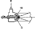
Fig. 2 is the sketch of the bubble jet device that preferably adopts of the device among Fig. 1;
Fig. 3 is the sketch of a heteroid bubble jet device and the radial diffuser that matches;
Fig. 4 is the sketch of the beginning part of the present invention's bubble jet device that the special shape center cone is arranged; With
Fig. 5 has a Laval shape to advance the sketch that sprays jet pipe on Fig. 4 sketch.
The specific embodiment
Fig. 1 is the sketch of flotation unit, and this device has the equipment that has been expanded by the saturated liquid of gas that makes of the present invention, and it makes the form of bubble jet device 4, and the required bubble of floatation forms in liquid in this equipment.Flotation cell 6 major parts own are full of suspension 5, and the foam 7 that forms on its liquid level comprises bubble and this suspension 5 contains the solid particle of removing with floatation as much as possible.This foam takes foam groove 8 to demister 16 and discharges as floating thing F.
Be pressurized to the saturation pressure 3-10 crust of requirement and be sent to saturated jar 2 with booster pump 1 from the part of the recycle stream K that purifies waste water.Be pressurized to the saturation pressure of requirement from the air of peripheral region with compressor 3, after this also deliver to saturated jar 2 and be dissolved in the liquid by strong quality transmission.So pressure increases to the liquid of saturation point and enters and be in particular the bubble jet device 4 that produces minimum bubble and design, to reduce pressure and to deliver to flotation cell 6 with the flow Z that contains solid, also may contain the flotation agent C of adding again, floatation process takes place therein.The bubble that pressure expansion forms is attached to taking liquid level on the hydrophobic solid and with it.The suspension that has cleaned with floatation leaves flotation cell as the K that purifies waste water.
Fig. 2 illustrates step-down of the present invention and produces the device 4 of minimum bubble.The liquid stream D that comes the pressure of self-saturation jar to reach saturation point enters and advances the bubble jet device 4 that sprays jet pipe 10 fronts.Changing the cross section that advances the annular gap between the cone 9 of spraying jet pipe 10 and having the central coaxial fixture can regulate advancing the necessary pressure drop of spraying in the jet pipe 10.For this reason, cone 9 can be pushed vertically or left to propelling and spray jet pipe 10.The above-mentioned cone 9 that preferably is contained on the screw rod 15 by rotation realizes that screw rod 15 rotates in threaded line.Because this rotatablely moves, any solid particle that may exist or flocculent deposit meeting are subjected to the effect of additional force, and this has cleaning action to advancing injection jet pipe 10.Leave and advance to spray jet pipe 10 and liquid stream, produce vacuum owing in pulse tube 12, scattering, thereby form more, particularly thinner bubble as free jet 11 through expanding suddenly.After by the diffuser 13 after being connected on pulse tube 12, microbubble decentralized photo M just leaves bubble jet device 4.
As shown in Figure 3, device 4 of the present invention is located immediately at the upstream of flotation cell 6.At this, a radial diffuser 17 is arranged in the flotation cell 6, be used to improve the distribution situation of the pulse tube 12 back bubble decentralized photos of bubble jet device 4, the pulse tube 12 here is preferably mounted on the flotation cell 6.
In the bubble jet device 4 of Fig. 4, regulate to advance spraying by the axial displacement of self on the conical inner body 9 of annular gap size of jet pipe 10 has additional stria 18.Therefore, can further improve the cleaning action that rotation cone 9 is brought.
Claims (12)
1. the method for impurity and suspension being separated with floatation, comprise to liquid aerating to saturation state, then the liquid that gas is saturated expands and forms bubble simultaneously, it is characterized in that: the saturated liquid of gas expands individually and before in containing the suspension that bubble liquid is added to impurity.
2. according to the method for claim 1, it is characterized in that: liquid just expands separately after inflation.
3. according to the method for claim 1 or 2, it is characterized in that: the liquid that gas is saturated expands with injection method.
4. according to the method for claim 3, it is characterized in that: the liquid that expands with the propulsive jet method of the saturated liquid of gas is ejected in the enclosure space, makes the diffusion of liquid stream.
5. according to each described method of claim 1-4, it is characterized in that: the pressure of liquid before expansion that gas is saturated is the 3-10 crust.
6. the device that impurity and suspension is separated with floatation, at least comprise to liquid aerating up to saturated equipment, then make the saturated liquid of gas expand and form the equipment of bubble, reach the equipment that joins alveolate liquid in the suspension and deliver to flotation cell, it is characterized in that: the equipment (4) that makes expansion of liquids is with in addition the equipment (2) in the suspension is arranged apart with alveolate liquid, and arranged apart with flotation cell (6).
7. produce the equipment of bubble in the saturated liquid of gas, it is characterized in that: the jet pipe that cross section is adjustable (10) is adjustable cross-sectional areas also preferably.
8. according to the device of claim 6, it is characterized in that: jet pipe (10) has annular opening.
9. according to the device of claim 6 or 7, it is characterized in that: the external boundary of jet pipe (19) is the shape of De Laval noz(zle).
10. according to claim 6,7 or 8 each described devices, it is characterized in that: the central segment that jet pipe (10) has cone (9) to constitute, it is restrained to enclosed area (12).
11. device according to claim 9 is characterized in that: cone (9) can move vertically and/or rotate around himself axis.
12. according to each described device of claim 6 to 10, it is characterized in that: the enclosed area is to constitute by being prismatic pulse tube (12) basically, preferably also connects an anemostat (13), and its cross section is with increasing away from jet pipe.
Applications Claiming Priority (2)
| Application Number | Priority Date | Filing Date | Title |
|---|---|---|---|
| AT0145701A AT410405B (en) | 2001-09-17 | 2001-09-17 | METHOD AND DEVICE FOR SEPARATING INTERFERENTS FROM SUSPENSIONS BY FLOTATION |
| ATA1457/2001 | 2001-09-17 |
Related Child Applications (1)
| Application Number | Title | Priority Date | Filing Date |
|---|---|---|---|
| CNA2005100921479A Division CN1727070A (en) | 2001-09-17 | 2002-09-16 | Device for separating impurities from a suspension by flotation |
Publications (2)
| Publication Number | Publication Date |
|---|---|
| CN1408480A true CN1408480A (en) | 2003-04-09 |
| CN1240481C CN1240481C (en) | 2006-02-08 |
Family
ID=3688250
Family Applications (2)
| Application Number | Title | Priority Date | Filing Date |
|---|---|---|---|
| CNA2005100921479A Pending CN1727070A (en) | 2001-09-17 | 2002-09-16 | Device for separating impurities from a suspension by flotation |
| CNB021431663A Expired - Fee Related CN1240481C (en) | 2001-09-17 | 2002-09-16 | Method and device for separating impurites from suspension by floatation method |
Family Applications Before (1)
| Application Number | Title | Priority Date | Filing Date |
|---|---|---|---|
| CNA2005100921479A Pending CN1727070A (en) | 2001-09-17 | 2002-09-16 | Device for separating impurities from a suspension by flotation |
Country Status (12)
| Country | Link |
|---|---|
| US (1) | US6730232B2 (en) |
| EP (1) | EP1293255B1 (en) |
| KR (1) | KR20030024630A (en) |
| CN (2) | CN1727070A (en) |
| AT (1) | AT410405B (en) |
| BR (1) | BR0203725A (en) |
| CA (1) | CA2398259A1 (en) |
| DE (1) | DE50205169D1 (en) |
| MX (1) | MXPA02009006A (en) |
| NO (1) | NO326283B1 (en) |
| NZ (1) | NZ521383A (en) |
| PL (1) | PL199064B1 (en) |
Cited By (1)
| Publication number | Priority date | Publication date | Assignee | Title |
|---|---|---|---|---|
| CN101837320A (en) * | 2010-04-09 | 2010-09-22 | 芬雷选煤工程技术(北京)有限公司 | Heavy medium coal preparation control equipment, density control system thereof and density control method |
Families Citing this family (9)
| Publication number | Priority date | Publication date | Assignee | Title |
|---|---|---|---|---|
| AT412535B (en) * | 2003-03-11 | 2005-04-25 | Andritz Ag Maschf | METHOD FOR REGULATING THE OPERATION OF A FLOTATION CELL |
| US7255332B2 (en) * | 2004-05-25 | 2007-08-14 | The Board Of Trustees Of The University Of Arkansas | System and method for dissolving gases in liquids |
| GB2423734B (en) * | 2005-03-03 | 2007-02-07 | Yorkshire Water Services Ltd | Dissolved gas flotation system and nozzle assembly |
| KR100749757B1 (en) * | 2007-05-16 | 2007-08-16 | 한국지질자원연구원 | Separation of unburned coal from briquette ash by flotation |
| ITPN20070064A1 (en) * | 2007-08-31 | 2009-03-01 | Enologica Friulana S A S | "SELF-CLEANING NOZZLE FOR CLARIFICATION DEVICES FOR FLOTATION" |
| DE102008056506A1 (en) * | 2008-11-08 | 2010-05-12 | Voith Patent Gmbh | mixing device |
| DE102008064271A1 (en) * | 2008-12-20 | 2010-07-01 | Voith Patent Gmbh | Process for the removal of solids from a fiber suspension by flotation and flotation for its implementation |
| FI20135868L (en) * | 2013-08-28 | 2015-03-01 | Outotec Finland Oy | Method and apparatus for treating a feed stream to a flotation device |
| CN106115834B (en) * | 2016-06-27 | 2020-02-14 | 叶志青 | Multi-stage aeration generator and sewage treatment method |
Family Cites Families (21)
| Publication number | Priority date | Publication date | Assignee | Title |
|---|---|---|---|---|
| US3175687A (en) * | 1962-09-24 | 1965-03-30 | Komline Sanderson Eng Corp | Flotation unit |
| FR2132497B1 (en) * | 1971-04-05 | 1974-04-05 | Degremont | |
| US3809240A (en) * | 1971-12-06 | 1974-05-07 | Degremont | Method of injecting fluids into a flotation tank |
| US3932282A (en) * | 1972-09-05 | 1976-01-13 | Tenco Hydro/Aerosciences, Inc. | Dissolved air floatation system |
| CA974335A (en) * | 1973-02-19 | 1975-09-09 | Joseph N. Parlette | Integral two stage clarifier |
| US3966598A (en) * | 1975-02-24 | 1976-06-29 | Tenco Hydro/Aerosciences, Inc. | Circular dissolved gas flotation system |
| FR2371968A1 (en) * | 1976-11-26 | 1978-06-23 | Guigues Sa | Effluent purification flotation cell - has weir on outer tank above inner supply tank and level with foam collector |
| US4337788A (en) * | 1981-02-02 | 1982-07-06 | Smith International Inc. | High pressure valve |
| US4413646A (en) * | 1981-05-01 | 1983-11-08 | Exxon Research And Engineering Co. | Streamline coal slurry letdown valve |
| US4503878A (en) * | 1983-04-29 | 1985-03-12 | Cameron Iron Works, Inc. | Choke valve |
| DE3444039A1 (en) * | 1984-12-03 | 1986-06-05 | Herion-Werke Kg, 7012 Fellbach | CONTROL VALVE |
| SU1337007A1 (en) * | 1985-11-20 | 1987-09-15 | Иркутский государственный университет им.А.А.Жданова | Homogenizing head |
| DE3717947A1 (en) * | 1987-05-27 | 1989-02-16 | Weiss Rosemarie | Method and apparatus for concentrating substances from liquids |
| FI891146A (en) * | 1989-03-10 | 1990-09-11 | Vesi Pauli Oy | MUNDSTYCKE, SOM AER LAETT ATT RENA, FOER DISPERSIONSVATTEN. |
| RU2021848C1 (en) * | 1990-08-07 | 1994-10-30 | Капцов Владимир Васильевич | Homogenizing valve for the production of highly dispersed emulsions |
| TW201295B (en) * | 1991-06-14 | 1993-03-01 | Sonnenrein Uwe | |
| DE4208370A1 (en) * | 1992-03-16 | 1993-09-23 | Fan Engineering Gmbh | Prodn. of very fine gas bubbles from high-pressure gasified liq. - involves subjecting liq. to pressure considerably below its vapour pressure |
| US5368273A (en) * | 1992-10-21 | 1994-11-29 | Allied Signal Inc. | Venturi metering system |
| CH685366A5 (en) * | 1992-12-09 | 1995-06-30 | Nestle Sa | Device for treating a fluid product by injection of steam. |
| DE19643054C2 (en) * | 1996-10-18 | 2003-02-27 | Ballard Power Systems | Valve with Laval nozzle and use of the same |
| DE19845536C2 (en) * | 1998-10-02 | 2001-11-22 | Voith Paper Patent Gmbh | Process for removing contaminants from an aqueous suspension containing paper fibers |
-
2001
- 2001-09-17 AT AT0145701A patent/AT410405B/en not_active IP Right Cessation
-
2002
- 2002-08-15 CA CA002398259A patent/CA2398259A1/en not_active Abandoned
- 2002-08-21 DE DE50205169T patent/DE50205169D1/en not_active Expired - Lifetime
- 2002-08-21 EP EP02018697A patent/EP1293255B1/en not_active Expired - Fee Related
- 2002-08-22 NO NO20024010A patent/NO326283B1/en not_active IP Right Cessation
- 2002-08-28 PL PL355745A patent/PL199064B1/en not_active IP Right Cessation
- 2002-09-12 BR BR0203725-4A patent/BR0203725A/en not_active Application Discontinuation
- 2002-09-13 NZ NZ521383A patent/NZ521383A/en unknown
- 2002-09-13 MX MXPA02009006A patent/MXPA02009006A/en active IP Right Grant
- 2002-09-16 CN CNA2005100921479A patent/CN1727070A/en active Pending
- 2002-09-16 CN CNB021431663A patent/CN1240481C/en not_active Expired - Fee Related
- 2002-09-17 KR KR1020020056581A patent/KR20030024630A/en not_active Application Discontinuation
- 2002-09-17 US US10/244,886 patent/US6730232B2/en not_active Expired - Fee Related
Cited By (2)
| Publication number | Priority date | Publication date | Assignee | Title |
|---|---|---|---|---|
| CN101837320A (en) * | 2010-04-09 | 2010-09-22 | 芬雷选煤工程技术(北京)有限公司 | Heavy medium coal preparation control equipment, density control system thereof and density control method |
| CN101837320B (en) * | 2010-04-09 | 2013-04-03 | 芬雷选煤工程技术(北京)有限公司 | Heavy medium coal preparation control equipment, density control system thereof and density control method |
Also Published As
| Publication number | Publication date |
|---|---|
| NZ521383A (en) | 2004-02-27 |
| EP1293255B1 (en) | 2005-12-07 |
| ATA14572001A (en) | 2002-09-15 |
| MXPA02009006A (en) | 2003-04-25 |
| EP1293255A3 (en) | 2004-03-03 |
| CA2398259A1 (en) | 2003-03-17 |
| US6730232B2 (en) | 2004-05-04 |
| AT410405B (en) | 2003-04-25 |
| CN1240481C (en) | 2006-02-08 |
| PL355745A1 (en) | 2003-03-24 |
| CN1727070A (en) | 2006-02-01 |
| BR0203725A (en) | 2003-06-03 |
| KR20030024630A (en) | 2003-03-26 |
| NO20024010L (en) | 2003-03-18 |
| NO20024010D0 (en) | 2002-08-22 |
| US20030070992A1 (en) | 2003-04-17 |
| NO326283B1 (en) | 2008-11-03 |
| DE50205169D1 (en) | 2006-01-12 |
| PL199064B1 (en) | 2008-08-29 |
| EP1293255A2 (en) | 2003-03-19 |
Similar Documents
| Publication | Publication Date | Title |
|---|---|---|
| CN1049845C (en) | Method and apparatus for dissolution and mixture of gas and liquid | |
| CN1269575C (en) | Method and device for fluid inflation | |
| CN1240481C (en) | Method and device for separating impurites from suspension by floatation method | |
| JP2000000447A (en) | Swirling type fine bubble generator | |
| CN1060453A (en) | The aeration of liquid | |
| EP0110529A2 (en) | High velocity fluid abrasive jet | |
| RU83944U1 (en) | DEVICE FOR TREATMENT OF LIQUID MEDIUM IN VORTEX FLOW | |
| JP2003245533A (en) | Ultrafine air bubble generator | |
| JP2007268390A (en) | Bubble generating device | |
| KR100577830B1 (en) | Swirling Fine-Bubble Generator | |
| JPH0747114B2 (en) | Gas-liquid contact device and ozone water production device | |
| RU2630087C1 (en) | Air cleaning device in vibration-boiling layer of liquid | |
| JP2004049938A (en) | Sludge treatment apparatus and method | |
| JP2004098030A (en) | Process and apparatus for separating impurities from suspension by separation floatation | |
| CN109603060B (en) | Special spray gun of air foam fire extinguishing apparatus | |
| CN203715321U (en) | Air flotation device | |
| WO2002002216A1 (en) | Method and device for feeding fine bubbles | |
| CN214115206U (en) | Jet flow micro-nano mixed water inlet device | |
| CN214347218U (en) | Micron dry fog ash-reducing device of flotation machine | |
| JPH07116647A (en) | Aeration device | |
| JP2009072664A (en) | Microbubble sprayer | |
| JP2021107665A (en) | Pumping system | |
| CN103723784A (en) | Floatation device | |
| RU2626820C1 (en) | Scrubber by kochetov | |
| RU2182524C1 (en) | Pneumatic floatation machine |
Legal Events
| Date | Code | Title | Description |
|---|---|---|---|
| C06 | Publication | ||
| PB01 | Publication | ||
| C10 | Entry into substantive examination | ||
| SE01 | Entry into force of request for substantive examination | ||
| C14 | Grant of patent or utility model | ||
| GR01 | Patent grant | ||
| C19 | Lapse of patent right due to non-payment of the annual fee | ||
| CF01 | Termination of patent right due to non-payment of annual fee |