CN1398132A - Portable terminal device - Google Patents
Portable terminal device Download PDFInfo
- Publication number
- CN1398132A CN1398132A CN02101768A CN02101768A CN1398132A CN 1398132 A CN1398132 A CN 1398132A CN 02101768 A CN02101768 A CN 02101768A CN 02101768 A CN02101768 A CN 02101768A CN 1398132 A CN1398132 A CN 1398132A
- Authority
- CN
- China
- Prior art keywords
- earphone
- earphone jack
- terminal
- external component
- voice path
- Prior art date
- Legal status (The legal status is an assumption and is not a legal conclusion. Google has not performed a legal analysis and makes no representation as to the accuracy of the status listed.)
- Pending
Links
Images


Classifications
-
- H—ELECTRICITY
- H04—ELECTRIC COMMUNICATION TECHNIQUE
- H04N—PICTORIAL COMMUNICATION, e.g. TELEVISION
- H04N1/00—Scanning, transmission or reproduction of documents or the like, e.g. facsimile transmission; Details thereof
- H04N1/00127—Connection or combination of a still picture apparatus with another apparatus, e.g. for storage, processing or transmission of still picture signals or of information associated with a still picture
- H04N1/00281—Connection or combination of a still picture apparatus with another apparatus, e.g. for storage, processing or transmission of still picture signals or of information associated with a still picture with a telecommunication apparatus, e.g. a switched network of teleprinters for the distribution of text-based information, a selective call terminal
- H04N1/00307—Connection or combination of a still picture apparatus with another apparatus, e.g. for storage, processing or transmission of still picture signals or of information associated with a still picture with a telecommunication apparatus, e.g. a switched network of teleprinters for the distribution of text-based information, a selective call terminal with a mobile telephone apparatus
-
- H—ELECTRICITY
- H04—ELECTRIC COMMUNICATION TECHNIQUE
- H04M—TELEPHONIC COMMUNICATION
- H04M1/00—Substation equipment, e.g. for use by subscribers
- H04M1/60—Substation equipment, e.g. for use by subscribers including speech amplifiers
- H04M1/6033—Substation equipment, e.g. for use by subscribers including speech amplifiers for providing handsfree use or a loudspeaker mode in telephone sets
- H04M1/6041—Portable telephones adapted for handsfree use
- H04M1/6058—Portable telephones adapted for handsfree use involving the use of a headset accessory device connected to the portable telephone
-
- H—ELECTRICITY
- H04—ELECTRIC COMMUNICATION TECHNIQUE
- H04M—TELEPHONIC COMMUNICATION
- H04M1/00—Substation equipment, e.g. for use by subscribers
- H04M1/72—Mobile telephones; Cordless telephones, i.e. devices for establishing wireless links to base stations without route selection
- H04M1/724—User interfaces specially adapted for cordless or mobile telephones
- H04M1/72403—User interfaces specially adapted for cordless or mobile telephones with means for local support of applications that increase the functionality
- H04M1/72409—User interfaces specially adapted for cordless or mobile telephones with means for local support of applications that increase the functionality by interfacing with external accessories
-
- H—ELECTRICITY
- H04—ELECTRIC COMMUNICATION TECHNIQUE
- H04N—PICTORIAL COMMUNICATION, e.g. TELEVISION
- H04N23/00—Cameras or camera modules comprising electronic image sensors; Control thereof
- H04N23/56—Cameras or camera modules comprising electronic image sensors; Control thereof provided with illuminating means
-
- F—MECHANICAL ENGINEERING; LIGHTING; HEATING; WEAPONS; BLASTING
- F21—LIGHTING
- F21V—FUNCTIONAL FEATURES OR DETAILS OF LIGHTING DEVICES OR SYSTEMS THEREOF; STRUCTURAL COMBINATIONS OF LIGHTING DEVICES WITH OTHER ARTICLES, NOT OTHERWISE PROVIDED FOR
- F21V33/00—Structural combinations of lighting devices with other articles, not otherwise provided for
- F21V33/0004—Personal or domestic articles
- F21V33/0052—Audio or video equipment, e.g. televisions, telephones, cameras or computers; Remote control devices therefor
-
- H—ELECTRICITY
- H04—ELECTRIC COMMUNICATION TECHNIQUE
- H04N—PICTORIAL COMMUNICATION, e.g. TELEVISION
- H04N2101/00—Still video cameras
-
- H—ELECTRICITY
- H04—ELECTRIC COMMUNICATION TECHNIQUE
- H04N—PICTORIAL COMMUNICATION, e.g. TELEVISION
- H04N2201/00—Indexing scheme relating to scanning, transmission or reproduction of documents or the like, and to details thereof
- H04N2201/0008—Connection or combination of a still picture apparatus with another apparatus
- H04N2201/0034—Details of the connection, e.g. connector, interface
- H04N2201/0036—Detecting or checking connection
Landscapes
- Engineering & Computer Science (AREA)
- Signal Processing (AREA)
- Human Computer Interaction (AREA)
- Multimedia (AREA)
- Computer Networks & Wireless Communication (AREA)
- Telephone Function (AREA)
- Telephonic Communication Services (AREA)
- Studio Devices (AREA)
- Telephone Set Structure (AREA)
Abstract
The present invention provided a portable terminal that enables a user to make a call or reproduce audio, by using a microphone and a loudspeaker, built in the portable terminal even when a flash unit is mounted on the portable terminal. A control circuit 20 is provided with an external unit identification function 20a and a voice path changeover control function 20b. When connections for plugs 40, 30 of an external unit to an earphone jack 25 is detected, the external unit identification function 20a determines whether the mounted external unit is an earphone unit EU or the flash unit FU. When the external unit plugged into the earphone jack is an earphone unit EU, the voice path changeover control function 20b connects the voice path to the earphone jack 25. When the external unit plugged into the earphone jack is a flush unit FU, the voice path changeover control function 20b connects the voice path to the built-in loudspeaker 13 and the built-in microphone 14 as its control.
Description
Technical field
The present invention relates to the mobile communication terminal of portable telephone and PHS (Personal Handyphone System, personal handyphone system) terminal etc., particularly relate to the mobile communication terminal that has camera function.
Background technology
In recent years, be that the mobile communication terminal of representative is popularized sharp with portable telephone and phs terminal etc., and developing as the mobile communication terminal that has camera function of a member wherein.This terminal installation, for example use CMOS (Complementary Metal Oxide Semiconductor has been installed in the shell upper of mancarried telephone device or the inside etc., CMOS (Complementary Metal Oxide Semiconductor)) video camera of etc. single imaging apparatus, in order to launch rest image or the moving image of taking by this video camera, for example with user's looks and scenery on every side, brochure and photo, catalogues etc. are transmitted to communication counterpart as image information, and this is very easily.In addition, generally, video camera will be difficult at night and the dark indoor image that obtains quality satisfaction of light with video camera separately only owing to its parts number of restriction and the sensitivity of size that is subjected to mobile communication terminal and price etc. all are restricted, and current present situation comes to this.
Therefore, present inventor etc. shown in patent 2001-179007 number, have proposed to utilize the earphone jack of mobile communication terminal, freely plug group following flash tube (abbreviating photoflash lamp later on as), thereby can carry out the formation of strobo photography.When adopting such formation, photoflash lamp can be contained in case of necessity and carry out strobo photography on the terminal installation, even if therefore at the dark satisfied image of quality that also can obtain such as indoor of night and light.On the other hand because can unload photoflash lamp when photographing when not photographing and by day with the bright place of light, so with mobile communication terminal in the dress flash function situation relatively, can keep the miniaturization and of mobile communication terminal.
, in this mobile communication terminal, exist following such problem that needs improvement.That is, general mobile communication terminal has, and when detecting when inserting headset plug in earphone jack, the voice path in the terminal installation dress microphone and loud speaker in the terminal automatically switch to the such formation of earphone jack.Therefore, for example behind the strobo photography, when the user is still adorning photoflash lamp and places terminal installation, exist, so post a letter and write letters user's such inconvenience of can not conversing even if exist in this state because dress microphone and loud speaker cut off from voice path in the terminal.When in adorning the state of photoflash lamp, not photographing, also can produce same inconvenience again.
The present invention is conceived to the problems referred to above, also can use in the terminal dress microphone and loud speaker is conversed or audio reproduction is such mobile communication terminal even if purpose of the present invention will provide in adorning the state of photoflash lamp.
Summary of the invention
In order to achieve the above object, the present invention has dress microphone and loud speaker and earphone jack in the terminal, can selectively earphone or photoflash lamp be inserted the mobile communication terminal of this earphone jack, except the recognition device that the external component that inserts above-mentioned earphone jack is discerned, also have the voice path switching device shifter.And, in this voice path switching device shifter, have when identification and be contained in external component in the above-mentioned earphone jack when being above-mentioned photoflash lamp, be formation such on above-mentioned microphone and the loud speaker with the connection destination setting in tut path.
If so according to the present invention, then when not photographing in the state of the earphone jack of inserting terminal installation at photoflash lamp, when still adorning photoflash lamp placement terminal installation again after the photography, if existing posts a letter write letters the user also can use in dress microphone and loud speaker converse, and can carry out the regeneration of the voice data of melody etc.
Feature of the present invention again is to be contained in external component in the above-mentioned earphone jack when being above-mentioned earphone when identification, and the connection destination of voice path also is set in the above-mentioned earphone jack.
When such formation, and the external component on being contained in above-mentioned earphone jack is when being earphone, automatically is set in the earphone jack the connection destination of voice path is the same as before.Therefore, even if the user does not carry out the handover operation of voice path especially,, just still can converse or audio reproduction by earphone as long as adorning earphone.
Further, feature of the present invention is also to have being connected on the display that has existed and finder that at least one side in the destination is presented at mobile communication terminal for example, to the annunciator of user report by the voice path determined with the recognition result of external component recognition device with by the voice path switching device shifter.
In formation as described above, for example when watching display or finder, the state of the mobile communication terminal the when user can confirm adorning external component.As above state in detail, the present invention has dress microphone and loud speaker and earphone jack in the terminal, can selectively in this earphone jack, insert the mobile communication terminal of earphone or photoflash lamp, except the recognition device that the external component that inserts above-mentioned earphone jack is discerned, also have the voice path switching device shifter.And this voice path switching device shifter has when identification is inserted external component in the above-mentioned earphone jack and is above-mentioned photoflash lamp, is above-mentioned microphone and the such formation of loud speaker with the connection destination setting in tut path.
If so, in adorning the state of photoflash lamp, also can use in the terminal dress microphone and loud speaker is conversed or the mobile communication terminal of audio reproduction even if then can provide according to the present invention.
Description of drawings
Fig. 1 is the figure that is illustrated in the outward appearance of the mobile communication terminal in the example of the present invention.
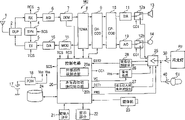
Fig. 2 is the block diagram that is illustrated in the circuit formation of the mobile communication terminal in the example of the present invention.
Fig. 3 is the block diagram that the major part of expression mobile communication terminal shown in Figure 2 constitutes.
Fig. 4 is identification and the connection control sequence of recognition result voice path and the program operation chart of content thereof of expression according to external component.
Fig. 5 is the figure that is illustrated in the structure of the earphone jack of the mobile communication terminal in the example of the present invention and photoflash lamp plug.
Fig. 6 is the figure that the circuit of expression earphone jack shown in Figure 5 constitutes.
Embodiment
Fig. 1 is the outside drawing of formation of the mobile communication terminal of the expression video camera that has an example of the present invention.
The mobile communication terminal of this example has earphone jack, can be selectively will freely insert this earphone jack as the earphone EU of external component and photoflash lamp FU or pull up from this earphone jack.
Previous section at mobile communication terminal MU is disposing key input part 21, display part 22 and video camera 23.In addition, the 1st, antenna.In the front of photoflash lamp FU, luminous component 31 and live part 32 are set.
On the other hand, Fig. 2 is the block diagram of the circuit formation of the above-mentioned mobile communication terminal MU of expression.
In Fig. 2, unillustrated base station is being received the back by antenna multicoupler (DUP) 2 input receiving circuits (RX) 3 by the radio carrier signal that radio channel sends by antenna from figure.In this receiving circuit 3, the radio carrier signal of above-mentioned reception and the reception oscillation signals according mixing of exporting, the intermediate-freuqncy signal that frequency translation becomes to receive from frequency synthesizer (SYN) 4.Then, this receiving intermediate frequency signal in comprising the A/D converter 6 of low frequency bandpass filter sampled after, be input to digital demodulating circuit (DEM) 7.
At digital demodulating circuit 7, after the frame synchronization and bit synchronization of having established, carry out digital demodulation and handle for above-mentioned digital received intermediate-freuqncy signal.To connect circuit (TDMA) 8 by the base-band digital restituted signal input time-division multiplex that this demodulation process obtains, there each transmission frame separation and Extraction be sent to the time slot of oneself.In addition, will notify control circuit 20 in frame synchronization and bit synchronous information that above-mentioned digital demodulating circuit obtains.
Then will be input to error correction code decoding circuit (CH-COD) 9, and carry out error correction decoding there and handle from the digital demodulation signal of above-mentioned TDMA circuit 8 outputs.This through the digital decoding signal behind error correction decoding in, exist the information data of the mail relevant etc., the voice data etc. of conversing with conversation form at this moment.The voice data of wherein will conversing is input to sound code decoding circuit (SP-COD) 10 and carries out the voice codec processing, the digital accepted call signal of regenerating thus.This digital accepted call signal changes back to simulation and is input to the unillustrated amplifier of being talked about among the figure by voice path commutation circuit 12a behind the accepted call signal in D/A converter 11, amplify there the back supply with in the output that amplifies of dress loud speaker 13.Again,, be kept in the memory (MEM) 24 and decode, on display part 22, show by this control circuit 20 with the information data input control circuit 20 of the mail that receives and the data download of reception etc.
On the other hand, caller's the sound of speaking is collected by interior dress microphone 14 and is transformed into telecommunication signal, further by among the figure unillustrated send the words amplifier be amplified to behind the fixed level, 12b is input to A/D converter 19 by the voice path commutation circuit.Then, in this A/D converter 19 with the fixed sampling period take a sample, thereby be transformed into the digital telecommunication signal that constitutes by sampling series.This digital telecommunication signal behind the elimination sound echo, is input to sound code decoding circuit (SP-COD) 10 in the unillustrated in the drawings Echo Canceller, carry out acoustic codingization there.
With this digital telecommunication signal input error correction code decoding circuit (CH-COD) 9, carry out error correction coding there through acoustic codingization.Again, also will import above-mentioned error correction code decoding circuit 9, carry out error correction coding from the information data of the view data of control circuit 20 output and emission mail etc.Then, will be input to TDMA circuit 8 from the digitally transmitted signals of these error correction code decoding circuit 9 outputs.In TDMA circuit 8, produce and the corresponding transmission frame of time-division multiplex connection (TDMA) mode, in the time slot of distributing to device oneself in this transmission frame, carry out in order to insert the processing of above-mentioned digitally transmitted signals.
Then will be from the digitally transmitted signals input digit modulation circuit (MOD) 15 of above-mentioned TDMA circuit 8 outputs.In digital modulation circuit 15, produce by above-mentioned digitally transmitted signals and carry out emission medium-frequency signal after the digital modulation, this emission medium-frequency signal is input to radiating circuit (TX) 5 after being transformed into analog signal by D/A converter 16.In addition, as digital modulation mode, for example use pi/4 shift DQPSK (π/4shifted, differentially encoded quadrature phaseshift keying, pi/4 shift, Differential Quadriphase Shift Keying) mode.
In radiating circuit 5, above-mentioned emission medium-frequency signal through ovennodulation carries out mixing with the emission oscillation signals according of exporting from frequency synthesizer 4, thereby is transformed into the radio carrier frequency corresponding with the dialogue channel.Then, with unillustrated emission power amplifier among the figure with this transmitting radio carrier signal be controlled on the fixed transmitted power level after, go out from antenna 1 unillustrated base station to figure by antenna multicoupler 2.
Again, this mobile communication terminal MU has key input part 21, display part 22, video camera 23, and memory (MEM) 24.
In addition, the 18th, power circuit on the basis of the output voltage of the battery 17 that is made of secondary cell (storage battery), produces for the required power source voltage Vcc of each circuit working of mobile communication terminal MU and makes the required charging voltage Vss of photoflash lamp FU charging.
In addition, this mobile communication terminal MU has the formation in order selectively to load onto earphone FU and photoflash lamp FU and to be used, and has earphone jack 25, and feed circuit 26, plug insert and pull away test section 27 and adorning identification division 28.
Earphone jack 25 is by tut path commutation circuit 12a, and 12b is connected with A/D converter 19 with D/A converter 11.This voice path commutation circuit 12a, the switching of 12b is to be controlled by the switch-over control signal CC1 from control circuit 20 outputs.
Feed circuit 26 only in the time, will be supplied with photoflash lamp FU at the feed of the feed control signal VC appointment that is provided by control circuit 20 from the charging voltage Vss of above-mentioned power circuit 18 outputs.Here as the above-mentioned feed time, the 2 class feed times of the 1st feed time and the 2nd feed time have for example been prepared.The 1st feed time was set to photoflash lamp FU is charged to the required enough time of electricity condition (for example 15 seconds) that is full of from A-stage always.The 2nd feed time was set to appends the required enough time of electricity condition (for example 10 seconds) that is full of that is charged to photoflash lamp FU from the partial discharge state.
Plug inserts the plug 40,30 pull away 27 couples of earphone EU in test section or photoflash lamp FU and detects to the insertion of above-mentioned earphone jack 25, and notifies control circuit 20 with this detected signal DET1.
Adorning identification division 28, pull away the plug 40 that external component is detected in test section 27 when inserting by above-mentioned plug, during 30 insertion, on the special terminal of earphone jack 25, add fixed identification voltage, whether this supervision is returned detection voltage by other special terminal from photoflash lamp FU foldback.Then, expression is had or not foldback return this component identification signal DET2 that adorning that detects voltage and notify control circuit 20.
External component recognition function 20a is by inserting the situation that the insertion detection signal DET1 that pulls away test section 27 outputs detects plug 40, the 30 insertion earphone jacks 25 of external component from plug.Then, when the plug 40,30 that detects this external component inserted, according to adorning component identification signal DET2 from what adorning identification division 28 notices, the external component that identification is being adorned was earphone EU or photoflash lamp FU.
Voice path switching control function 20b, be for the connection status of voice path being controlled according to the recognition result of said external component identification function 20a, when the external component that inserts earphone jack 25 is earphone EU, make voice path, promptly D/A converter 11 is connected with earphone jack 25 with A/D converter 19.On the other hand, when the external component that inserts earphone jack 25 is photoflash lamp FU, D/A converter 11 is connected respectively with interior dress microphone 14 with interior dress loud speaker 13 with A/D converter 19.
On the other hand, following formation photoflash lamp FU and plug 30 thereof.Fig. 3 is the figure of this formation of expression.
Photoflash lamp FU has the luminous component 31 with flashbulb, uses the live part 32 of neon tube, and power receiving section divides 33, electric capacity 34, stimulus part 35 and delay control section 36.
Wherein power receiving section divides 33 will give electric capacity 34 from the charging voltage Vss that above-mentioned mobile communication terminal MU supplies with and charge.Stimulus part 35 receives from the led control signal FRS of above-mentioned mobile communication terminal MU output.Postpone control section 36 and make the led control signal FRS that exports from above-mentioned stimulus part 35 only postpone predefined time of delay and give luminous component 31, thereby make the charging voltage discharge of electric capacity 34 carry out luminous.
That is, at first terminal A is as the electrified terminal of charging voltage Vss, contacts with the terminal T2 of the position, deep that is configured in earphone jack 25.The terminal assignment that will be used for feed give the reason of terminal T2 of the position, deep of earphone jack 25 be for the process that pulls away of the insertion at plug 30 can not make plug 30 be used to touched with the terminal T2 misconnection that is used for feed by the terminal beyond the terminal A of electricity.
Terminal B is used separately as and is used for plug and inserts and to pull away the electricity that is subjected to that detects and adorning component identification voltage and use terminal, contacts with the terminal T3 of earphone jack 25.Terminal C contacts with the terminal T6 of earphone jack 25 as earth terminal.Terminal D contacts with the terminal T1 of earphone jack 25 as the reception terminal of led control signal FRS.
Terminal E is connected with above-mentioned terminal B in plug, contacts with the terminal T7 of earphone jack 25.In such formation, the component identification voltage of adorning that is added on the above-mentioned terminal B is got back to mobile communication terminal MU as the terminal T7 by earphone jack 25 from the detected voltage foldback of the terminal E of plug 30.
Secondly, the identification of the external component FU among our explanation and the above such mobile communication terminal MU that constitutes and voice path is connected the relevant work of controlling.Fig. 4 is the program operation chart of its control sequence of expression and content.
That is, mobile communication terminal MU in the step 4b that is undertaken by control circuit 20, inserts earphone jack 25 to the plug of external component and monitors.In this state, at first the user will carry out by the conversation of earphone EU or the audio reproduction of use earphone EU, in the plug 40 insertions above-mentioned earphone jack 25 of step 4a with earphone EU.
When doing like this, pull away test section 27 output detection signal DET1 from the plug insertion, control circuit 20 recognizes that by this detection signal DET1 the plug of external component inserts at step 4b.When plug inserts earphone jack 25, will adorn the terminal B that component identification voltage is added to plug from adorning identification division 28.At this moment, if the plug of plug is the plug 40 of earphone EU, then will adorning component identification voltage and be returned to mobile communication terminal MU.
So, when this state begins to converse, by voice path commutation circuit 12a and earphone jack 25 after earphone EU output receiving demodulation and the decoding processing D/A converter 11 up conversions become analog signal the other side speaker talked about voice signal.To this, the words voice signal of being imported by the microphone of earphone EU that send is input to A/D converter 19 by earphone jack 25 and voice path commutation circuit 12b, is transformed into there and send the words voice data, is further launching after through encoding process and modulation.
Again, when the audio reproduction of beginning melody etc., reading voice data from memory 24 carries out decoding processing and D/A conversion, thereby by voice path commutation circuit 12a and earphone jack 25 simulated audio signal from earphone EU output regeneration.
Like this, the user can converse or appreciate the voice data of melody etc. by using earphone EU.
On the other hand, when the user will carry out strobo photography, the plug 30 of photoflash lamp FU is inserted the earphone jack 25 of mobile communication terminal MU.When doing like this, identical with the situation of foregoing earphone EU, pull away test section 27 output detection signal DET1 from the plug insertion, control circuit 20 recognizes that by this detection signal DET1 the plug of external component inserts at step 4b.
When plug inserts above-mentioned earphone jack 25, will adorn the terminal B that component identification voltage is added to plug from adorning identification division 28 again.At this moment, if the plug that inserts is the plug 40 of aforesaid earphone EU, then will detect voltage and be returned to mobile communication terminal MU., if the plug that inserts is the plug 30 of photoflash lamp FU, then because plug 30 in, connect between this terminal B and the terminal E, so the above-mentioned component identification voltage of adorning intactly is returned to as detection voltage from terminal E and is adorning identification division 28.Then, will adorn identification signal DET2 notice control circuit 20 from adorning identification division 28.Control circuit 20 is received the above-mentioned notice of adorning identification signal DET2 at step 4c, recognizes that the external component of adorning is photoflash lamp FU.
In addition, when detecting when adorning photoflash lamp FU, proceed to step 4f below the control circuit 20, make voice path there, promptly D/A converter 11 is connected with interior dress microphone 14 with interior dress loud speaker 13 respectively with A/D converter 19.Then, at step 4g, with the Working mode set of mobile communication terminal MU use pattern at photoflash lamp FU.Again simultaneously, 22 demonstrate and set photoflash lamp FU and use the message or the sign of pattern and made voice path and message or sign that interior dress loud speaker 13 and interior dress microphone 14 couple together in the display part.
So, press the charging key that will make photoflash lamp FU charging this state user.Control circuit 20 beginning feed controls when doing like this.As a result, from feed circuit 26 charging voltage Vss is supplied with photoflash lamp FU, therefore make electric capacity 34 chargings by the terminal T4 of earphone jack 25 and the terminal A of plug 30.Then, after charging finishes, when the user presses shutter key on mobile communication terminal MU, produce led control signal FRS from control circuit 20, the terminal T1 by earphone jack 25 and the terminal D of plug 30 send to this led control signal FRS the stimulus part 35 of photoflash lamp FU.Then, this led control signal FRS being delayed 36 of control sections postpones to be added to luminous component 31 behind the certain hour.Therefore, carry out luminous work at luminous component 31 by the discharge of the charging voltage of electric capacity 34.
On the other hand, adorning in the state of photoflash lamp FU the letter of posting a letter in earphone jack 25.When doing like this, mobile communication terminal MU temporarily gets back to call mode from flash of light use pattern, implements the work in order to converse.
That is, make by the regeneration of receiving demodulation and decoding processing talked about voice data after D/A converter 11 up conversions become analog signal, by voice path commutation circuit 12a from the output that amplifies of interior dress loud speaker 13.To this, the words voice signal that send that will import interior dress microphone 14 by voice path commutation circuit 12b is input to A/D converter 19, is transformed into there and send the words voice data, further launches after carrying out encoding process and modulating.So even if in the state of adorning photoflash lamp FU, when posting a letter letter, dress microphone 14 and interior dress loud speaker 13 carry out mobile phone communication in also can using.
As mentioned above in this example, external component recognition function 20a and voice path switching control function 20b are set on control circuit 20, when the plug 40 that detects external component, during 30 insertion earphone jacks 25, the external component that is inserted by external component recognition function 20a identification is earphone EU or photoflash lamp FU.Then, when the external component that inserts earphone jack 25 is earphone EU,, voice path is connected with earphone jack 25 by voice path switching control function 20b.On the other hand, when the external component that inserts earphone jack 25 is photoflash lamp FU, make voice path be connected such control with interior dress microphone 14 with interior dress loud speaker 13 by voice path switching control function 20b.
So, still be inserted in the earphone jack 25 of mobile communication terminal MU but in the state of not photographing at photoflash lamp FU, again in the situation of after photography, still adorning photoflash lamp FU placement mobile communication terminal MU, if there is the distribution letter, dress microphone 14 and interior dress loud speaker 13 conversed in then can using, and can carry out the regeneration of the voice data of melody etc.
When the external component that inserts earphone jack 25 is earphone EU, the connection destination of voice path automatically is set in the earphone jack 25 as before again.Therefore, even if the user does not carry out the handover operation of voice path especially,, just can converse or audio reproduction by earphone as long as still inserting earphone EU.
Further, message or the sign of switching controls result by making expression recognition result of external component and voice path show on display part 22, the user can confirm the kind of the external component adorned and the connection status of voice path when watching display part 22 or finder.
In addition, the present invention is not limited to above-mentioned example, and for example except portable telephone and phs terminal, the present invention also can be applicable to portable information terminal (PDA) and portable voice frequency phonograph, pocket guider, clock and watch etc.
In addition, even if formation for mobile communication terminal, the shape of earphone and photoflash lamp and formation, the structure of earphone jack and each external component plug, external component adorning recognition methods, with the switching controls of voice path order and content thereof etc., in the scope that does not break away from main idea of the present invention, also can carry out all distortion.
Claims (3)
1. mobile communication terminal, its feature are that it is to have dress microphone and loud speaker in the terminal, and earphone jack, can selectively earphone and flash tube be inserted the mobile communication terminal of this earphone jack, possess
The external component that above-mentioned earphone jack is inserted in identification be above-mentioned earphone or flash tube the external component recognition device and
When the external component that inserts above-mentioned earphone jack when said external component recognition apparatus identification is above-mentioned flash tube, be the voice path switching device shifter of above-mentioned microphone and loud speaker with the connection destination setting of voice path.
2. the mobile communication terminal of claim item 1 record, its feature is that it further has when the external component of the above-mentioned earphone jack of said external component recognition apparatus identification insertion is above-mentioned earphone, and the tut path switching device is the function of above-mentioned earphone with the connection destination setting of voice path.
3. the mobile communication terminals of claim item 1 or 2 records, its feature are the annunciators that at least one side in the destination reports to the user that is connected that it further has the voice path determined with the recognition result of said external component recognition apparatus with by the tut path switching device.
Applications Claiming Priority (2)
| Application Number | Priority Date | Filing Date | Title |
|---|---|---|---|
| JP2001212719A JP2003032333A (en) | 2001-07-12 | 2001-07-12 | Portable terminal |
| JP212719/2001 | 2001-07-12 |
Publications (1)
| Publication Number | Publication Date |
|---|---|
| CN1398132A true CN1398132A (en) | 2003-02-19 |
Family
ID=19047830
Family Applications (1)
| Application Number | Title | Priority Date | Filing Date |
|---|---|---|---|
| CN02101768A Pending CN1398132A (en) | 2001-07-12 | 2002-01-18 | Portable terminal device |
Country Status (4)
| Country | Link |
|---|---|
| US (1) | US6819942B2 (en) |
| EP (1) | EP1276309A2 (en) |
| JP (1) | JP2003032333A (en) |
| CN (1) | CN1398132A (en) |
Cited By (6)
| Publication number | Priority date | Publication date | Assignee | Title |
|---|---|---|---|---|
| US7184807B2 (en) | 2002-11-15 | 2007-02-27 | Nec Corporation | Cellular phone and attachment thereof |
| CN100372188C (en) * | 2004-06-23 | 2008-02-27 | 金宝电子工业股份有限公司 | Simplification and simplifying device for detecting audio-visual signal wire and earphone signal wire |
| CN1859813B (en) * | 2005-09-28 | 2010-10-27 | 华为技术有限公司 | Signal switching method for internal and external microphone |
| CN101924835A (en) * | 2010-08-17 | 2010-12-22 | 惠州Tcl移动通信有限公司 | Mobile telephone communication method and mobile telephone |
| CN103544958A (en) * | 2013-11-04 | 2014-01-29 | 深圳Tcl新技术有限公司 | Method and device for controlling voice-frequency howling during switching of voice-frequency output |
| CN113271530A (en) * | 2021-05-20 | 2021-08-17 | 深圳市通标科技有限公司 | Plug-pull detection method and device of earphone equipment |
Families Citing this family (36)
| Publication number | Priority date | Publication date | Assignee | Title |
|---|---|---|---|---|
| TW483624U (en) * | 2000-06-17 | 2002-04-11 | Dyna Data System Corp | Portable power supply and data storage device |
| US20020183118A1 (en) * | 2001-05-30 | 2002-12-05 | Scott Wolinsky | Method and apparatus for simulating game accessories |
| KR100640347B1 (en) * | 2002-03-12 | 2006-10-30 | 삼성전자주식회사 | Apparatus and method for recognizing connection to digital camera or ear-microphone in a mobile communication terminal equipment |
| US20030211888A1 (en) * | 2002-05-13 | 2003-11-13 | Interactive Telegames, Llc | Method and apparatus using insertably-removable auxiliary devices to play games over a communications link |
| KR100486527B1 (en) * | 2002-08-17 | 2005-05-03 | 엘지전자 주식회사 | Photographing control apparatus for mobile communication terminal with camera |
| TW563995U (en) * | 2002-12-20 | 2003-11-21 | Benq Corp | Mobile device with auto-answer function |
| EP1455513A1 (en) | 2003-03-03 | 2004-09-08 | Sony Ericsson Mobile Communications AB | Portable flash device as accessory to a mobile communication equipment |
| KR20040090577A (en) | 2003-04-17 | 2004-10-26 | 주식회사 팬택앤큐리텔 | The Apparatus and Method to Sensing Strobo of Wireless Communication Terminal Automatically |
| JP4130388B2 (en) * | 2003-08-04 | 2008-08-06 | 株式会社半導体エネルギー研究所 | Liquid crystal display |
| TWM243842U (en) * | 2003-08-07 | 2004-09-11 | Cotron Corp | Car charger for cellular pone with illuminating function and illuminating apparatus |
| KR100544460B1 (en) | 2003-11-21 | 2006-01-24 | 삼성전자주식회사 | Method and Apparatus for volume control using volume key in remote controller in ?? device |
| DE102004014751A1 (en) * | 2004-03-25 | 2005-10-20 | Cxo Network Gmbh | Illuminating device for connecting to a mobile telephone having camera comprises a lighting unit operated by a triggering unit and an energy storage unit connected to the triggering unit and the lighting unit to supply a current |
| US7904188B2 (en) | 2004-10-26 | 2011-03-08 | Panasonic Corporation | Information outputting device, information output controlling method, and information output controlling program |
| TWI264625B (en) * | 2005-02-05 | 2006-10-21 | High Tech Comp Corp | Audio/charging switching module and electronic system and portable electronic device applying the same |
| KR100684918B1 (en) | 2005-04-01 | 2007-02-22 | 삼성전자주식회사 | Mobile communication terminal for playing music file and a method thereof |
| KR20060109770A (en) * | 2005-04-18 | 2006-10-23 | 엘지전자 주식회사 | Sound output control method for audio device |
| CN100377059C (en) * | 2005-09-02 | 2008-03-26 | 英华达(南京)科技有限公司 | Mobile media play electronic devices sharing earphone transportation end and signal transfer wire |
| KR100652178B1 (en) | 2005-11-10 | 2006-11-29 | 주식회사 이노와이어리스 | Voice cable interface apparatus for mobile station testing device |
| KR100754825B1 (en) * | 2006-06-30 | 2007-09-04 | 삼성전자주식회사 | Apparatus and method for mobile commerce providing in a portable terminal |
| US20080001816A1 (en) * | 2006-06-30 | 2008-01-03 | Bily Wang | Portable wireless earphone apparatus with a global positioning system |
| FR2907923B1 (en) * | 2006-10-31 | 2009-02-27 | Signoptic Technologies Soc Par | ACCESSORY FOR A PORTABLE COMMUNICABLE TERMINAL EQUIPPED WITH MEANS OF PROCESSING AND ACQUIRING IMAGES AND ASSEMBLY FORMED BY THE ACCESSORY AND THE COMMUNICATING TERMINAL |
| US7995140B2 (en) | 2006-12-06 | 2011-08-09 | Signoptic Technologies | Add-on for a communicating terminal comprising imaging means and assembly comprising the add-on and the communicating terminal |
| US7912501B2 (en) | 2007-01-05 | 2011-03-22 | Apple Inc. | Audio I/O headset plug and plug detection circuitry |
| TW200913471A (en) * | 2007-09-01 | 2009-03-16 | D2Audio Corp | Systems and methods for controlling HDA system capabilities |
| CN101465906B (en) * | 2007-12-19 | 2012-07-18 | 鸿富锦精密工业(深圳)有限公司 | Portable electronic device |
| TWI420885B (en) * | 2007-12-31 | 2013-12-21 | Hon Hai Prec Ind Co Ltd | Portable electric device |
| DE102010060511B4 (en) * | 2010-11-11 | 2012-12-13 | Sma Solar Technology Ag | Method for operating an external device via a bidirectional audio connection |
| US9052758B2 (en) * | 2010-12-31 | 2015-06-09 | Blackberry Limited | System and method for detecting accidental peripheral device disconnection |
| JP5798943B2 (en) * | 2011-05-20 | 2015-10-21 | 京セラ株式会社 | Mobile terminal, earphone identification program, and earphone identification method |
| FR2993997B1 (en) * | 2012-07-26 | 2014-08-22 | Acep France | PHOTOGRAPHIC LIGHTING SYSTEM FOR TOUCH TABLET |
| US9681241B2 (en) * | 2013-02-26 | 2017-06-13 | Blackberry Limited | Apparatus, systems and methods for detecting insertion or removal of an audio accessory from an electronic device |
| CN103795853B (en) * | 2013-11-15 | 2016-01-20 | 深圳光启智能光子技术有限公司 | The connection switching method of earphone interface adapting appts and terminal |
| US9584893B2 (en) * | 2014-01-20 | 2017-02-28 | Fairchild Semiconductor Corporation | Apparatus and method for recovering from partial insertion of an audio jack |
| US9794708B2 (en) | 2014-01-20 | 2017-10-17 | Fairchild Semiconductor Corporation | Apparatus and method for detecting insertion anomaly of an audio jack |
| US9807919B2 (en) * | 2014-01-29 | 2017-10-31 | Apple Inc. | Electronic devices having electrostatic discharge paths |
| US9497369B1 (en) * | 2015-05-27 | 2016-11-15 | Chia-Ching Lin | Complex control device and selfie apparatus |
Family Cites Families (5)
| Publication number | Priority date | Publication date | Assignee | Title |
|---|---|---|---|---|
| JP3255995B2 (en) * | 1992-10-23 | 2002-02-12 | 株式会社日立製作所 | Videophone equipment |
| US5893037A (en) * | 1994-12-09 | 1999-04-06 | Eastman Kodak Company | Combined electronic/silver-halide image capture system with cellular transmission capability |
| US6122526A (en) * | 1997-04-24 | 2000-09-19 | Eastman Kodak Company | Cellular telephone and electronic camera system with programmable transmission capability |
| JPH10210546A (en) * | 1997-01-17 | 1998-08-07 | Sony Corp | Radio communication system, stationary station equipment and mobile station equipment |
| US6681120B1 (en) * | 1997-03-26 | 2004-01-20 | Minerva Industries, Inc., | Mobile entertainment and communication device |
-
2001
- 2001-07-12 JP JP2001212719A patent/JP2003032333A/en not_active Withdrawn
-
2002
- 2002-01-18 CN CN02101768A patent/CN1398132A/en active Pending
- 2002-03-22 US US10/102,834 patent/US6819942B2/en not_active Expired - Fee Related
- 2002-03-26 EP EP02006677A patent/EP1276309A2/en not_active Withdrawn
Cited By (8)
| Publication number | Priority date | Publication date | Assignee | Title |
|---|---|---|---|---|
| US7184807B2 (en) | 2002-11-15 | 2007-02-27 | Nec Corporation | Cellular phone and attachment thereof |
| CN1320839C (en) * | 2002-11-15 | 2007-06-06 | 日本电气株式会社 | Cellular phone and attachment thereof |
| CN100372188C (en) * | 2004-06-23 | 2008-02-27 | 金宝电子工业股份有限公司 | Simplification and simplifying device for detecting audio-visual signal wire and earphone signal wire |
| CN1859813B (en) * | 2005-09-28 | 2010-10-27 | 华为技术有限公司 | Signal switching method for internal and external microphone |
| CN101924835A (en) * | 2010-08-17 | 2010-12-22 | 惠州Tcl移动通信有限公司 | Mobile telephone communication method and mobile telephone |
| CN103544958A (en) * | 2013-11-04 | 2014-01-29 | 深圳Tcl新技术有限公司 | Method and device for controlling voice-frequency howling during switching of voice-frequency output |
| CN103544958B (en) * | 2013-11-04 | 2018-02-27 | 深圳Tcl新技术有限公司 | Switch the method and apparatus for controlling Audio squealing during audio output |
| CN113271530A (en) * | 2021-05-20 | 2021-08-17 | 深圳市通标科技有限公司 | Plug-pull detection method and device of earphone equipment |
Also Published As
| Publication number | Publication date |
|---|---|
| EP1276309A2 (en) | 2003-01-15 |
| US20030013499A1 (en) | 2003-01-16 |
| JP2003032333A (en) | 2003-01-31 |
| US6819942B2 (en) | 2004-11-16 |
Similar Documents
| Publication | Publication Date | Title |
|---|---|---|
| CN1398132A (en) | Portable terminal device | |
| CN1126402C (en) | Earphone-microphone combination including radio receiver module and switching method of its operation mode between telephone mode and radio receiver mode | |
| US6741835B2 (en) | Systems and methods for communications | |
| JPH05276098A (en) | Cordless telephone master set | |
| CN1465171A (en) | Camera equipped cellular telephone | |
| CN101414724A (en) | Micro USB compatible combo system connector | |
| CN101119399B (en) | Blue tooth loudspeaker | |
| EP1990982A1 (en) | Integrated communication apparatus comprising a Bluetooth headset | |
| EP0569314B1 (en) | Equipment for coupling one or several conventional telephone sets to a cellular radio network | |
| CN102143573A (en) | Method and device for data transmission | |
| CN100527766C (en) | Speaker apparatus and method in a wireless telephone | |
| CN1848987A (en) | Double-standard mobile communication terminal | |
| CN2521850Y (en) | Double-channel hand mobile telephone set | |
| EP1220522A3 (en) | Call screening in a cordless digital system | |
| CN202551161U (en) | Mobile phone with terminals capable of automatic muting during conversations | |
| US20070232273A1 (en) | Method of providing an electronic answering function to a wireless phone | |
| JP2001127874A (en) | Radio telephone system, radio telephone equipment, communication equipment, radio communication method and storage medium | |
| JP3535479B2 (en) | Mobile terminal unit | |
| CN104993868B (en) | Fixed-line telephone extension method and system | |
| KR200223843Y1 (en) | The receiving converter of mobilephone use to charger | |
| JP4406257B2 (en) | Mobile device | |
| CN117857686B (en) | Communication method, communication system and related device | |
| KR20010039082A (en) | Apparatus for wire and wireless video telephone by using video portable telephone | |
| JP2838460B2 (en) | Connection device to public telephone line in PHP | |
| JP2992723B2 (en) | Connection device to public telephone line in PHP |
Legal Events
| Date | Code | Title | Description |
|---|---|---|---|
| C10 | Entry into substantive examination | ||
| SE01 | Entry into force of request for substantive examination | ||
| C06 | Publication | ||
| PB01 | Publication | ||
| C10 | Entry into substantive examination | ||
| SE01 | Entry into force of request for substantive examination | ||
| C02 | Deemed withdrawal of patent application after publication (patent law 2001) | ||
| WD01 | Invention patent application deemed withdrawn after publication |