CN1324428A - Fold-down handle device - Google Patents
Fold-down handle device Download PDFInfo
- Publication number
- CN1324428A CN1324428A CN99812706.XA CN99812706A CN1324428A CN 1324428 A CN1324428 A CN 1324428A CN 99812706 A CN99812706 A CN 99812706A CN 1324428 A CN1324428 A CN 1324428A
- Authority
- CN
- China
- Prior art keywords
- mentioned
- handle
- handling device
- pallet
- cam member
- Prior art date
- Legal status (The legal status is an assumption and is not a legal conclusion. Google has not performed a legal analysis and makes no representation as to the accuracy of the status listed.)
- Pending
Links
Images


Classifications
-
- E—FIXED CONSTRUCTIONS
- E05—LOCKS; KEYS; WINDOW OR DOOR FITTINGS; SAFES
- E05B—LOCKS; ACCESSORIES THEREFOR; HANDCUFFS
- E05B7/00—Handles pivoted about an axis parallel to the wing
-
- E—FIXED CONSTRUCTIONS
- E05—LOCKS; KEYS; WINDOW OR DOOR FITTINGS; SAFES
- E05C—BOLTS OR FASTENING DEVICES FOR WINGS, SPECIALLY FOR DOORS OR WINDOWS
- E05C3/00—Fastening devices with bolts moving pivotally or rotatively
- E05C3/006—Fastening devices with bolts moving pivotally or rotatively about an axis parallel to the surface on which the fastener is mounted
- E05C3/008—Fastening devices with bolts moving pivotally or rotatively about an axis parallel to the surface on which the fastener is mounted parallel to the wing edge
-
- E—FIXED CONSTRUCTIONS
- E05—LOCKS; KEYS; WINDOW OR DOOR FITTINGS; SAFES
- E05C—BOLTS OR FASTENING DEVICES FOR WINGS, SPECIALLY FOR DOORS OR WINDOWS
- E05C3/00—Fastening devices with bolts moving pivotally or rotatively
- E05C3/02—Fastening devices with bolts moving pivotally or rotatively without latching action
- E05C3/06—Fastening devices with bolts moving pivotally or rotatively without latching action with operating handle or equivalent member moving otherwise than rigidly with the bolt
-
- E—FIXED CONSTRUCTIONS
- E05—LOCKS; KEYS; WINDOW OR DOOR FITTINGS; SAFES
- E05C—BOLTS OR FASTENING DEVICES FOR WINGS, SPECIALLY FOR DOORS OR WINDOWS
- E05C5/00—Fastening devices with bolts moving otherwise than only rectilinearly and only pivotally or rotatively
-
- Y—GENERAL TAGGING OF NEW TECHNOLOGICAL DEVELOPMENTS; GENERAL TAGGING OF CROSS-SECTIONAL TECHNOLOGIES SPANNING OVER SEVERAL SECTIONS OF THE IPC; TECHNICAL SUBJECTS COVERED BY FORMER USPC CROSS-REFERENCE ART COLLECTIONS [XRACs] AND DIGESTS
- Y10—TECHNICAL SUBJECTS COVERED BY FORMER USPC
- Y10T—TECHNICAL SUBJECTS COVERED BY FORMER US CLASSIFICATION
- Y10T292/00—Closure fasteners
- Y10T292/08—Bolts
- Y10T292/1043—Swinging
- Y10T292/1075—Operating means
- Y10T292/1077—Cam
-
- Y—GENERAL TAGGING OF NEW TECHNOLOGICAL DEVELOPMENTS; GENERAL TAGGING OF CROSS-SECTIONAL TECHNOLOGIES SPANNING OVER SEVERAL SECTIONS OF THE IPC; TECHNICAL SUBJECTS COVERED BY FORMER USPC CROSS-REFERENCE ART COLLECTIONS [XRACs] AND DIGESTS
- Y10—TECHNICAL SUBJECTS COVERED BY FORMER USPC
- Y10T—TECHNICAL SUBJECTS COVERED BY FORMER US CLASSIFICATION
- Y10T292/00—Closure fasteners
- Y10T292/08—Bolts
- Y10T292/1043—Swinging
- Y10T292/1075—Operating means
- Y10T292/1083—Rigid
-
- Y—GENERAL TAGGING OF NEW TECHNOLOGICAL DEVELOPMENTS; GENERAL TAGGING OF CROSS-SECTIONAL TECHNOLOGIES SPANNING OVER SEVERAL SECTIONS OF THE IPC; TECHNICAL SUBJECTS COVERED BY FORMER USPC CROSS-REFERENCE ART COLLECTIONS [XRACs] AND DIGESTS
- Y10—TECHNICAL SUBJECTS COVERED BY FORMER USPC
- Y10T—TECHNICAL SUBJECTS COVERED BY FORMER US CLASSIFICATION
- Y10T292/00—Closure fasteners
- Y10T292/57—Operators with knobs or handles
Landscapes
- Engineering & Computer Science (AREA)
- Mechanical Engineering (AREA)
- Purses, Travelling Bags, Baskets, Or Suitcases (AREA)
- Details Of Rigid Or Semi-Rigid Containers (AREA)
Abstract
A fold-down handle device for attachment to a first member, such as a panel, to provide a controlled pushing and pulling action on actuation for facilitating insertion and retraction of the first member to a second member, such as a cabinet, the handle device including a handle with a gripping portion, a cam member, a pawl member and a drive pin connecting the pawl member to the handle and extending through a slot provided in the cam member to regulate the movement of the pawl when the handle is lifted from a folded horizontal position to an upright vertical position.
Description
Background of invention
1. invention field
The present invention relates to the locking devicen field, especially, relate to the locking devicen that a kind of handle with collapsible handle activates.
2. prior art
In many purposes, all rely on locking devicen with parts for example fastenings such as panel door, casing, rack and dividing plate be in the same place, and be used for the parts fastening in panel or rack.For example, usually adopt various retention mechanisms that electronic unit is fixed in panel or the rack, or be fixed on circuit board or other members.Above-mentioned rack has the door that can lock, so that each parts can be put into cabinet.Some rack or member can have the slide track component that electronic unit is installed, and are used to insert or shift out electronic unit.In general, the parts itself that are installed in slide track component or the rack can be accepted many leads that are connected with it or connector.Usually must take out electronic unit for place under repair, improvement or replacing operation.In some cases, slide track component preferably has the correlation of handle and related application.
Application is that whole disclosures of above-mentioned patent application are quoted as a reference in this article in the part continuation application of the U.S. Patent application No.09/181181 of submission on October 28th, 1998.Hand or handle are so that take out parts from rack or casing etc. easily.In many cases, above-mentioned handle can be a kind of can be by the handle of the protrusion of the permanent fixation of user's grasping insert panel in other words or pull out outside the panel so that parts are slipped into.
In some cases, handle or handle also can adopt hinge to connect, thereby can they are folding, to save the space.The space of saving is big more, just more parts can be inserted in the rack, and more the person can use less rack.
But, in some purposes, often will be at the hot parts that insert down.Power supply unit is that a class will be contained in the parts in the rack.For example, in some purposes, power supply unit can " hot swap ", and this just requires to change power supply unit in the equipment continuous running.In this purposes, insert and take out power supply unit and require usually when power supply unit is placed into and take out, respectively the electric connector in the power supply unit be inserted and transfer to.The weight of power supply unit can surpass 20 pounds usually, therefore needs quite big power just can take out power supply unit from rack or casing, also will push above-mentioned electric connector aside simultaneously.And, in case packing into, power supply unit location in rack, panel or other members, just wishes it is remained on the link position, and the disengagement that can not meet accident owing to unexpected power, vibration, heat or other reasons.
Though can use lock bolt and fastener with above-mentioned parts for example power supply unit be fixed on the panel,, wish to use as far as possible little space, and make the volume size of panel or other members reduce to minimum so that reserve the place as miscellaneous part.In locking devicen, used the cam control action.For example, grant people such as Glenn E.Anderson on December 23rd, 1997 and transfer in the U.S. Patent No. 5669638 " fastener " of Southco company and disclose a kind of fastener that has the cam mechanism that can be used to the pull sliding part, whole disclosures of this patent are quoted as a reference in this article.
Need and a kind ofly can when activating, produce the controlled thrust and the following folding formula handle of pulling force, so that insert or withdraw from the parts that above-mentioned handle is installed.
Summary of the invention
The present invention proposes a kind ofly to be used for fixing the novel following folding formula handling device on the member so that produce controlled thrust and pulling force and be convenient to insert respectively and withdraw from the parts that above-mentioned handling device has been installed when this device activates, and described folding formula handling device down also has a kind of retaining mechanism that above-mentioned handle stops its actuating of locking.Above-mentioned handle is provided with grip part and is used to activate folding handling device, above-mentioned grip part also can be used to carry the installation of taking off from panel the parts of collapsible handling device maybe these parts are moved to panel or the member that will insert.
An object of the present invention is to propose a kind of locking devicen, wherein, the jackknife action of handle can make this locking devicen activate.
Another object of the present invention is that actuating by the swing of winding by hand pivot being realized pallet is to move into and to shift out pallet.
But a further object of the present invention provides a kind of fastening handle to prevent it the retaining mechanism of unallowed actuating takes place.
Another purpose of the present invention provides a kind of with the retaining mechanism of handlebar locked on its folding position.
Another purpose of the present invention is to propose a kind ofly to may be locked on the folding position and can promote and remain on handle on the upright position.
A further object of the present invention is handle to be made the above-mentioned purpose of realization under the situation that is roughly U-shaped spare.
A further object of the present invention is handle to be made the above-mentioned purpose of realization under the situation that is roughly T shape part.
The accompanying drawing summary
Describe embodiments of the invention in detail below in conjunction with accompanying drawing, in the accompanying drawing:
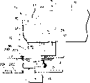
Fig. 1 looks one-point drawing in the end of first embodiment of folding formula handling device down of the present invention;
Fig. 1 a is the local enlarged side view of the following folding formula handling device of Fig. 1, and the position of pallet with respect to cam member is shown;
Fig. 2 is the one-point drawing of cam member of the handling device of Fig. 1;
Fig. 3 is the front elevation drawing of pallet of the handling device of Fig. 1;
Fig. 4 is mounted on first panel and the lateral view of the handling device of the Fig. 1 that is connected with second panel;
Fig. 5 is mounted in the top plan view of the handling device of the Fig. 1 on the panel;
Fig. 6 is the rear elevation of the handling device of Fig. 5;
Fig. 7 is of the present invention is installed on the panel and with the right side view of second embodiment of the following folding formula handling device of this panel fastening on frame;
Fig. 8 is the decomposition assembling figure of each parts of the handling device of Fig. 7; With
Fig. 9 is the one-point drawing of the handling device of Fig. 7 and 8.
Preferred embodiment describes in detail
Referring to Fig. 1, folded formula handling device 10 down of the present invention shown in the figure, this device 10 has the handle 11 as actuating mechanism.Above-mentioned handling device 10 also has: pair of cams 12 and 13; One is fixed on the mechanism that tightens up on panel or the miscellaneous part with handling device 10, and this tightens up mechanism and has a pair of fastener 14 and 15; With a mechanism for card of pulling with a pair of pallet 16,17.
Can know at Fig. 1 and 5 and to find out that handle 11 has the grip 20 and a pair of supporting leg 21,22 that stretches out from grip 20 that are convenient to user's grasping.One end of each supporting leg 21,22 is connected with grip 20, and its other end then has a mechanism that handle 11 is connected with cam member 12,13.
Above-mentioned bindiny mechanism preferably has a securing member for example can pass the pin 24,25 that is arranged on the corresponding pin-and- hole 26,27 in each supporting leg 21,22 of handle.Cam member 12,13 has the hole of aiming at the pin-and- hole 26,27 of first supporting leg 21 and second supporting leg 22 30,31 ' respectively, is used to make pin 24,25 (see figure 5) that is connected with respective cams part 12,13 respectively.Handle 11 is connected with cam member 12,13 swingably.Though pin shown in the figure 24,25 also will be understood, any handle 11 that makes can be used with the suitable fasteners that cam member 12,13 is connected swingably.
The part of pair of cams shown in the figure 12,13, they have the first wall 31,32 and second wall 33,34 of inner each self-forming guide groove 35,36 respectively.For first cam member 12, make the cam path 37,38 in the first wall 31 that lays respectively at cam member 12 and second wall 33, similarly, second cam member 13 also has the cam path 39,40 that is separately positioned in the first wall 32 and second wall 34.
Fig. 2 illustrates first cam member 12 separately. Cam path 37,38 is aligned with each other, and passes the actuator pin 43 of the actuating pin-and-hole 44 in first supporting leg 21 of handle 11 with admittance.
As shown in Figure 5, the inside of first supporting leg 21 has a groove 46 that is defined its each limit by leg wall 47 and 48.In each wall 47,48 of first supporting leg 21, make separately and activate pin-and-hole 44,45.Second supporting leg 22 of handle 11 also has the leg wall 50 and 51 of common formation groove 52, also makes respectively activating pin-and-hole 53,54 in each leg wall 50,51.Actuator pin 42 is installed in the pin-and-hole 53,54 of second supporting leg 22.
As shown in Figure 3, the mechanism for card of pulling has the pallet 16 that an inside has support slot 60, and makes a notched bonding part 61 at an end of this pallet 16.The pallet 17 that is shown in Fig. 1 is made too has a support slot 62 and a bonding part 63.Referring to Fig. 1, pallet 17 is installed in the handle locking devicen 10.Trundle 43 is passed the support slot 62 of pallet 17 and pallet 17 is fixed in the handle locking devicen 10.Make pallet 16,17 put into first and second cam members 12,13 guide groove 35,36 separately respectively movably.
With actuator pin 24,25 supporting leg 21,22 of handle 11 is connected swingably respectively with cam member 12,13.The axis of oscillation of handle has been stipulated in the position of actuator pin 24,25.When handle 11 is raised so that activate and when its fixing axis of oscillation 24,25 rotated, the actuator pin 42,43 that passes pallet support slot 60,62 respectively can be mobile the cam path 37,38 of first cam member 12 in and in the cam path 39,40 of second cam member 13 respectively.Shown in Fig. 1 and 5, handle 11 is arranged to roughly meet at right angles with cam member 12,13.When handle 11 is promoted to upright position (shown in the direction of arrow " a ") with respect to cam member 12,13, just pallet 16,17 reduces from cam member 12,13.Preferably, handle locking devicen 10 is installed on the parts, reduced pallet at 16,17 o'clock so that it is activated mentioning handle 11.The parts of mounting knob locking devicen 10 are just unclamped in the reduction of pallet 16,17.Above-mentioned parts can be the power supply units that for example has plug or connector, when handle 11 action, but just uncoupling and unclamp and from the mechanism that originally tightened up it or device, take out of above-mentioned power supply unit itself.
Fixed mechanism is used for handle device 10 is fixed to a kind of parts for example on panel or the rack.Said fixing mechanism is shown in Fig. 1 and 4, preferably has a pair of leg 70,71 that is separately positioned on first cam member 12 and second cam member 13.This leg 70 and 71 is the same, so a following explanation leg 70 (this leg 70 is connected with first cam member 12).Can be clear that from Fig. 1,2 and 6, leg 70 has a upper flange 72, a lower flange 73 and the support slot 74 between overhead cam 72 and lower flange 73, and the inside of leg 70 also has one can handle the groove 76 of admitting pallet 16 when pallets 16 rise and descend at handle 11.Fixed mechanism also is provided with a fastener 14.This fastener 14 has a pair of pole 80,81 that separately forms a groove 82 between them, preferably a kind of spring part of supporting member 14.Want the panel of mounting knob locking devicen 10 or parts should have the hole that can pass for leg 70,71, then by being installed in respectively that supporting member 14,15 on each leg 70,71 inserts in the hole with leg 70,71 because of fixing on the panel.The pole 80,81 of above-mentioned supporting member 14 can be received within the groove 74 that forms between the upper flange 72 of leg 70 and the lower flange 73.
Shown in Figure 1A, actuator pin 43 is fixed to pallet 16 on the handle 11, actuator pin 43 is positioned at the terminal of support slot 60, pallet 16 has a jointing edge 87 that engages with the restraint limit 88 (Fig. 2) of first cam member 12, the terminal part (see Figure 1A) relevant with actuator pin 43 of above-mentioned pallet 16 can make pallet 16 do shifted laterally with respect to cam member 12, and this feature helps guaranteeing that pallet breach 61 fully and fastener or the miscellaneous part or the surperficial uncoupling (see figure 4) of fixed detents.For example, if pallet 16 is connected with plug or connector, the above-mentioned feature of unclamping just is convenient to extract out above-mentioned plug or connector.
Be provided with detent mechanism make handle 11 remain on its extreme position-open (vertical) fully or close (level) position fully.For example, make handle 11 remain on the position component that is approximately perpendicular to fixed handle locking devicen 10, so that grasp handle 11 by detent mechanism.For convenience in locking, handle 11 is remained on its horizontal level in other words on the folding position.Shown detent mechanism has a last depression 85 (on cam path 38 cell walls same depression being arranged also) on the cell wall that is arranged on cam path 37, and effect of depression 85 is that handle 11 is remained on (Fig. 6) on the crawl position on this, and pallet 16 is thrown off fully.Detent mechanism also has a following depression 86 (same following depression also is set) on the cell wall that is arranged on cam path 37 on cam path 38 cell walls.The effect of this time depression 86 is that handle 11 is remained on the locked position.Detent mechanism releasably fixed handle 11 selectively moves into it and moves apart this position location.
Referring to Fig. 4, handle locking devicen 10 is installed on first panel 200 and tightens up second panel 201.Pallet 16 stretches in the rectangular opening 202 that is arranged on second panel 201.When handle 11 tightens up the position when being drawn high to its vertical released position in other words along the direction of arrow " a " from its horizontal level, pallet 16 just is on its occupied released position, and is shown in dotted line.Handle locking devicen 10 is by being installed on first panel 200 in the otch 203 on leg 70 insertions first panel 200 of its cam member 12.The leg 70 of the fastener 14 and first cam member 12 joins to merging first cam member 12 is fixed on first panel 200.Though a side of device 10 only is shown among the figure,, should be understood that the relative opposite side of handle also is installed on first panel 200, and tighten up second panel 201 in an identical manner.
Though handle shown in the figure 11 has the supporting leg 21,22 that is connected with pair of cams part 12,13, also can propose a kind of alternative embodiment, for example, its handle has only single supporting leg and adopts single cam member.Again for example, single supporting leg handle can be made a kind of " T " font structure.
Below referring to Fig. 7, second alternative embodiment of fold-down handle device shown in the figure 110.This second alternative embodiment 110 is similar to first embodiment 10, but the operating bar that its actuation mechanism has an action that is used to control pallet 116 is start handle 111 in other words, and the shape of above-mentioned pallet 116 is with top to combine the described pallet of first embodiment shown in Fig. 1~6 16 similar.Pallet 116 has the support slot 160 and the abutting end (see figure 8) with footing 161 that it can be fixed on the handling device 110.The profile that should be understood that abutting end can be made with the various locking members that meet the principle of the invention and move.Be provided with any precalculated position that is connected that a breach 162 is convenient to pallet 116 its disengagements fully of aligning and locking member or other members at the back of pallet 116.Above-mentioned breach preferably can make pallet 116 recoils and leave this locking member (not shown).
Preferably a kind of rod shaped structure that has lift portion 119 on its free end of handle 111 tightens up pallet 116 to get loose the engaging of parts from it and locking member or other so that mention handle 111 easily and comes.Above-mentioned lift portion 119 preferably has curve shape, so as when to promote handle 111 and user's finger or thumb adapt.
Referring to the assembly drawing of Fig. 8, handle 111 has a pair of supporting leg of stretching 120,121 below, and this supporting leg separates each other and constitutes a space 129 jointly.Be provided with a bindiny mechanism handle 111 is connected with the cam mechanism 117 of housing 112, described bindiny mechanism can be a securing member for example, for example passes the actuator pin 124 that is separately positioned on the corresponding pin-and-hole 126,127 in the supporting leg 120,121.Has a hole 130 that is used to settle above-mentioned actuator pin 124 on the housing 112, so that handle 111 is installed in rotation on the housing 112 by pin 124.Though there is shown circular pin 124,, should be understood that anyly handle 111 to be installed in rotation on suitable connector on the housing 112 for example rivet, screw etc. can be used.Above-mentioned handle 111 is made down the folding formula, can be from rolling over to the position shown in the solid line under the position shown in the dotted line of Fig. 7.
Cam mechanism 117 has a pallet holding groove 150 that is used to admit pallet 116 that is arranged in the cam member.As shown in Figure 7, pallet 116 partly is received in the pallet holding groove 150 of cam member 117, and protruding from the mounting portion 151 of housing 112.Referring again to Fig. 8, pallet holding groove 150 is defined by first housing wall 131 and second housing wall 132, makes cam path 137,138 respectively on first housing wall 131 and second housing wall 132.This two cam path 137,138 faces one another and is aligned with each other, and passes for actuator pin 143.
Above-mentioned actuator pin 143 passes the actuating pin-and-hole 144,145 that is separately positioned in the handle supporting leg 120,121, and passes the support slot 160 in the pallet 116 and pallet 116 is fixed on the handle locking devicen 110.Handle 111 can be around the rotational that pin 124 is installed, and the actuator pin 143 that is fixed on the handle supporting leg 120,121 penetrates again in the cam path 137,138.
As shown in Figure 7, handle 111 is positioned at the position that is approximately perpendicular to housing 112.When handle 111 when the direction of arrow " b " rises to position (shown in dotted line 111 ' among the figure) perpendicular to housing, just pallet 116 descends from housing 112.When foldable handle locking devicen 110 preferably was mounted to and falls pallet 116 when promoting handle 111, pallet 116 just broke away from fixed part 220.Described fixed part can be for example frame, framework, a casing etc. of any suitable member.Preferably as shown in Figure 7, fold-down handle device 110 can be installed in a kind of plate for example on the front panel 221 of electric supply installation or other devices, for example the said fixing parts can be the power supply units that for example has plug or electric connector, when handle 111 is moved, itself just can throw off above-mentioned parts, so that parts are taken out from the mechanism of originally fixing it or device.
In Fig. 7, foldable handle locking devicen 110 is installed on the panel 221, and with tightening up mechanism collapsible handle locking devicen 110 is fixed on panel or the miscellaneous part.Can adopt the tighten up mechanism relevant shown in Fig. 1 and 4 (above) that housing 112 is installed on the panel 221 with the first collapsible handle locking devicen that implements 10.This tightens up mechanism and has the leg 170 that is arranged on the housing 112, and the both sides of this leg 170 respectively are provided with groove 171,172, also is provided with locking breach 173 on groove 171, also is provided with same locking breach (not shown) on groove 172.
Be provided with fastener inserted sheet 180 in other words in addition, handle locking devicen 110 is clamped on the panel 221.As shown in Figure 9, fastener 180 has a pair of pole 183,184, is provided with a barb 181,182 respectively on each pole 183,184, and this barb 181,182 is used for engaging with locking breach 173, for example, barb 181 shown in Figure 7 snaps in the breach 173.Adopt barb 181,182 to be convenient to handle locking devicen 110 is fixed on installing component or the surperficial for example front panel shown in Fig. 7 and 9 221.Fastener preferably a kind of elastic component of inserted sheet 180 in other words for example is suitable for housing 112 is fixed to the elastic component that the elastomeric material on the panel is made with spring steel, plastics and other.Shown in Fig. 7 and 9, the leg 170 of housing 112 passes on the front panel 221 hole 225 that forms, and 180 of fastener are stuck on the leg 170 and collapsible handle locking devicen 110 is fixed on the panel 221.
The pallet that is in a fixed position 116 shown in Figure 8, it engages the hole 230 interior (see figure 9)s that footing 161 inserts framework panel 220.When handle 111 when solid line position is promoted to the dotted line position (see figure 7), pallet 116 is deviate from from framework panel 220, promptly moves to position shown in the dotted line pallet 116 ' from its solid line position.
The parts of wanting mounting knob position latching 110 for example front panel 221 will prepare the hole 225 what a can pass for housing leg 170.Then by fastener 180 being installed on the leg 170 and leg 170 is fixed on the panel 221.
Referring again to Fig. 8.The breach 162 that is arranged on pallet 116 backs is being controlled when promoting handle 111 pallet 116 with respect to the position of housing 112.This breach 162 can form additional gap in pallet holding groove 150, so that pallet 116 is withdrawn into it on position 116 ' shown in Figure 7.
The mechanism for card of pulling is used for making handle 111 to be positioned at respectively closing and closes position and raised position.For example, make pocket portion 147,148 respectively, also make corresponding pocket portion (not shown) at each end of another relative cam path 138 at each end of cam path 137.This pocket portion 147,148 is convenient to make actuator pin 143 location, makes the position that pallet 116 and framework panel 220 tighten up or makes the position of pallet 116 from 220 withdrawals of framework panel so that it remains in cam path 137,138.Actuator pin 143 drops to extreme position 111 ' and pallet 116 position 116 ' when framework panel 220 is thrown off of outside handle when (143 ') of pocket portion 147 in cam path 137 corresponding.When handle 111 rose to this position, pallet 116 was moved laterally to position 116 ' shown in the dotted line with respect to housing 112.This feature helps guaranteeing that the end 161 on the pallet breaks away from fastener, miscellaneous part or the surface that is connected with it fully.For example, if pallet 116 is connected with plug or connector, above-mentioned feature can be convenient to extract out above-mentioned plug or connector.
The above-mentioned mechanism for card of pulling is also as detent mechanism, is used for making handle 111 to remain on its extreme position one and opens the position of (vertically) fully or close fully on the position of closing (level).This detent mechanism releasably supports the handle 111 that optionally moves into and shift out institute's allocation.
The most handy retaining mechanism fixed handle 111 makes it can accident not open.This retaining mechanism is locked handle 111 mutually with housing 112, so pallet 116 can not activate.Fig. 8 illustrates above-mentioned retaining mechanism, and it has first securing member 190 and second securing member 191.First securing member 190 is installed in the hole 192 interior (see figure 9)s of handle 111, and housing 112 has the bearing 194 of supporting second securing member 191.Second securing member 191 is positioned at the position that aligns with first securing member 190 in housing 112.First and second securing members 190,191 are connected and handle 111 are fixed on the housing 112.Spring 195 preferably is set, so as with first securing member (twist pin) 190 from promoting with second securing member (socket) 191.And be provided with lining ring guard ring 196 in other words, convenient twist pin 190 is fixed on the handle 111 to prevent that it and handle 111 from colliding.
Above-mentioned securing member can be the quarter-turn securing member twistlock and the socket of piece number 190,191 expression (as: respectively with) for example.Twist pin 190 and socket 191 can be by U.S. Southco. company (Concordville, PA) Gong Ying member.Other securing member also can be used for the present invention.For example, can also adopt the securing member of collision type retaining mechanism and screw or instrument shape, in addition, can also or tighten up mechanism with key lock or other suitable locking.
Persons skilled in the art can understand, can carry out various remodeling to handling device of the present invention under the situation of scope and spirit of the present invention, the present invention will cover various improvement and the remodeling of in the scope of stipulating in appended claims and the reciprocity file thereof handling device being done.
Claims (19)
1. one kind is fixed to second parts such as the handling device on the rack with first parts, and it has:
A) actuating mechanism;
B) cam mechanism;
C) mechanism for card of pulling;
D) above-mentioned handling device is remained on maintaining body on above-mentioned first parts;
E) wherein, above-mentioned actuating mechanism is installed on the above-mentioned cam mechanism swingably;
F) wherein, above-mentioned cam mechanism is installed on the first above-mentioned parts by above-mentioned maintaining body; With
G) wherein, the above-mentioned mechanism for card of pulling comprises the mechanism that above-mentioned pallet is installed to the mechanism on the above-mentioned handle and engages with above-mentioned second parts.
2. one kind is fixed to second parts such as the handling device on the rack with first parts, and it has:
A) handle that has grip;
B) at least one cam member, it has the installing mechanism that attaches it on first parts that will load onto above-mentioned handling device, this cam member has the first wall portion and the second wall portion that is separated by connecting wall, and the inside of the above-mentioned first wall portion and the second wall portion is provided with the groove that is roughly arc respectively;
C) pallet; With
D) a kind of bindiny mechanism, wherein, above-mentioned pallet is connected with above-mentioned handle by above-mentioned bindiny mechanism; With
E) wherein, above-mentioned pallet is movably between the above-mentioned first wall portion and the above-mentioned second wall portion of above-mentioned cam member.
3. according to the handling device of claim 2, it is characterized in that above-mentioned bindiny mechanism has an above-mentioned deep-slotted chip breaker that can pass the above-mentioned first and second cam member wall portions so that the drive pin that can move along above-mentioned groove when above-mentioned handling device action.
4. according to the handling device of claim 2, it is characterized in that, above-mentioned handle also has at least one from the outwardly directed supporting leg of above-mentioned grip, first end of this supporting leg is connected with above-mentioned grip, and a groove is set in second end, this second end and above-mentioned at least one cam member are pivotably connected.
5. according to the handling device of claim 4, it is characterized in that, at least have two cam members, wherein, above-mentioned handle has the outwardly directed supporting leg in a pair of both sides from above-mentioned grip, wherein, the handle supporting leg that each is above-mentioned and a cam member are pivotably connected, so that around a rotational, above-mentioned pallet is connected with each supporting leg, and each above-mentioned pallet can be swung with respect to above-mentioned handle.Each above-mentioned cam member has the vertical channel that a first wall portion by each cam member, the second wall portion and connecting wall portion partly define, and wherein, each pallet is received within the vertical channel of each cam, makes it vertically to move up and down in groove.
6. according to the handling device of claim 2, it is characterized in that also having to be arranged on and be used on each above-mentioned cam member this cam member is remained on maintaining body on above-mentioned first parts.
7. according to the handling device of claim 2, it is characterized in that, above-mentioned handle can move to non-folding released position from the folding position that tightens up, above-mentioned handling device also has the socket on above-mentioned first parts of the locking member of a grip that is arranged on above-mentioned handle and at least one above-mentioned cam member of installation disposed thereon, this socket is aimed at above-mentioned locking member when above-mentioned handle is in its folding position, wherein, above-mentioned pallet stretches out in above-mentioned cam member when above-mentioned handle is in its non-folding released position, and is in it at above-mentioned handle and folding bounces back in above-mentioned cam member when tightening up the position.
8. according to the handling device of claim 2, it is characterized in that also having handle is fixed on fixed mechanism on the upright position.
9. according to the handling device of claim 3, it is characterized in that, also have handle is fixed on fixed mechanism on the upright position, its feature also is, said fixing mechanism has being used on each end that is arranged on each above-mentioned deep-slotted chip breaker and optionally remains on the depression of the drive pin on the end of above-mentioned groove.
10. according to the handling device of claim 5, it is characterized in that also having handle is fixed on fixed mechanism on the horizontal level.
11. the handling device according to claim 10 is characterized in that, above-mentioned fixed mechanism comprises and is used on the end that is arranged on each above-mentioned deep-slotted chip breaker bindiny mechanism is kept putting within it depression.
12. the handling device according to claim 3 is characterized in that, also has handle optionally is fixed on fixed mechanism on one of upright position or horizontal level.
13. handling device according to claim 12, it is characterized in that, above-mentioned fixed mechanism have one on the end that is arranged on each above-mentioned deep-slotted chip breaker first depression and second depression on other end that is arranged on each above-mentioned deep-slotted chip breaker, wherein, above-mentioned drive pin is kept by above-mentioned depression, so that handle is optionally remained on one of horizontal level or upright position.
14. handling device according to claim 3, it is characterized in that, one side of above-mentioned pallet comprises the joined wall of an inclination, be used for engaging with the connecting wall of above-mentioned at least one cam member, wherein, have in the above-mentioned pallet that an above-mentioned drive pin of confession passes so that the groove that above-mentioned pallet is connected with handle, the groove of this pallet forms a cam surface that makes this pallet with respect to the drive pin location.
15. handling device according to claim 14, it is characterized in that, above-mentioned drive pin makes above-mentioned pallet be connected with handle, and be passed in the above-mentioned groove that is roughly arc that forms in the above-mentioned cam member, with the above-mentioned handle of box lunch folding water level put and non-folding upright position between the amount of movement of control pallet when mobile.
16. handling device according to claim 2, it is characterized in that, above-mentioned handle can move to non-folding released position from folding restraint location, above-mentioned handling device also has the locking member and the socket that is arranged on above-mentioned above-mentioned first parts that at least one above-mentioned cam member is installed that are arranged on the grip of above-mentioned handle, this socket is when handle is in its folding position and above-mentioned fastener alignment, wherein, above-mentioned pallet stretches out in above-mentioned cam member when above-mentioned handle is in its non-folding released position, then bounce back in above-mentioned cam member when above-mentioned handle is in its folding restraint location.
17. handling device according to claim 5, it is characterized in that, above-mentioned handle can move to non-folding released position from folding restraint location, above-mentioned handling device also have one on the grip that is arranged on above-mentioned handle locking member and the socket on above-mentioned first parts that an above-mentioned cam member is installed at least disposed thereon, this socket is when above-mentioned handle is in its folding position and above-mentioned fastener alignment, wherein, above-mentioned pallet stretches out in above-mentioned cam member when above-mentioned handle is in its non-folding released position, then bounce back in above-mentioned cam member when above-mentioned handle is in its folding restraint location.
18. one kind is fixed to for example handling device on the rack of second parts with first parts, it has:
A) actuating mechanism;
B) housing that has cam mechanism;
C) mechanism for card of pulling;
D) above-mentioned locking devicen is remained on maintaining body on above-mentioned first parts;
E) wherein above-mentioned actuating mechanism is installed on the above-mentioned cam mechanism swingably;
F) wherein above-mentioned cam mechanism is installed on the first above-mentioned parts by above-mentioned maintaining body;
G) the wherein above-mentioned mechanism for card of pulling have with above-mentioned pallet be installed on the above-mentioned handle member and for the member of the second above-mentioned part bonding; With
H) fixing above-mentioned actuating mechanism is to stop the mechanism that moves with respect to above-mentioned housing.
19. handling device according to claim 18, it is characterized in that above-mentioned fixing above-mentioned actuating mechanism is a kind of retention mechanism that has first securing member that is arranged on the above-mentioned actuating mechanism and be arranged on second securing member in the above-mentioned housing to stop mobile mechanism.
Applications Claiming Priority (2)
| Application Number | Priority Date | Filing Date | Title |
|---|---|---|---|
| US18118198A | 1998-10-28 | 1998-10-28 | |
| US09/181,181 | 1998-10-28 |
Publications (1)
| Publication Number | Publication Date |
|---|---|
| CN1324428A true CN1324428A (en) | 2001-11-28 |
Family
ID=22663232
Family Applications (1)
| Application Number | Title | Priority Date | Filing Date |
|---|---|---|---|
| CN99812706.XA Pending CN1324428A (en) | 1998-10-28 | 1999-10-27 | Fold-down handle device |
Country Status (6)
| Country | Link |
|---|---|
| US (1) | US6203076B1 (en) |
| EP (1) | EP1127207A4 (en) |
| CN (1) | CN1324428A (en) |
| AU (1) | AU1238400A (en) |
| TW (1) | TW414828B (en) |
| WO (1) | WO2000024996A1 (en) |
Cited By (3)
| Publication number | Priority date | Publication date | Assignee | Title |
|---|---|---|---|---|
| CN100443689C (en) * | 2004-07-31 | 2008-12-17 | 索斯科公司 | Ratcheting pawl latch |
| CN101627174A (en) * | 2007-01-05 | 2010-01-13 | 亚当斯莱特欧洲有限公司 | Lock assembly |
| US12077999B1 (en) * | 2018-11-17 | 2024-09-03 | Regalo International, Llc | Oblique slide latch apparatus |
Families Citing this family (23)
| Publication number | Priority date | Publication date | Assignee | Title |
|---|---|---|---|---|
| US6513841B1 (en) * | 2000-10-10 | 2003-02-04 | Hartwell Corporation | Blowout latch |
| DE10196815T5 (en) * | 2000-11-06 | 2004-04-29 | Southco, Inc. | Device with swivel handle |
| US6469247B1 (en) * | 2000-11-16 | 2002-10-22 | Robroy Industries, Inc. | Enclosure |
| EP1392942A4 (en) | 2001-06-01 | 2008-11-12 | Southco | Latch with bail-type mounting |
| US6565167B1 (en) * | 2001-07-06 | 2003-05-20 | Apple Computer, Inc. | Removable computer core with retractable handle mechanism |
| US7665775B1 (en) * | 2001-08-03 | 2010-02-23 | Hughes Supply Company Of Thomasville, Inc. | Locking window having a cam latch |
| US7325846B2 (en) * | 2003-05-07 | 2008-02-05 | Hewlett-Packard Development Company, L.P. | Low profile mechanical assist hood latch |
| US7397674B2 (en) * | 2003-06-09 | 2008-07-08 | Southco, Inc. | Compact PCI ejector latch |
| US7159283B2 (en) * | 2004-09-15 | 2007-01-09 | Nextronics Engineering Corp. | Locking device for a panel |
| US20060185406A1 (en) * | 2005-02-19 | 2006-08-24 | Penn Elcom, Inc. | Locking latch assembly |
| US7354293B2 (en) * | 2006-02-14 | 2008-04-08 | Ablecom Technology, Inc. | Fastening positioning device for a handle of a power supply |
| DE102006057490A1 (en) * | 2006-12-06 | 2008-06-12 | Jungheinrich Ag | Pallet truck with locking device for a battery block |
| US8256737B2 (en) * | 2008-03-14 | 2012-09-04 | Southco, Inc. | Leverage device and system using same |
| US8072317B2 (en) * | 2008-07-16 | 2011-12-06 | Johnson Electric S.A. | Haptic solenoid system |
| CN104508596B (en) | 2012-07-07 | 2017-06-20 | 思博有限责任公司 | Tactile actuator |
| US9436341B2 (en) | 2012-12-21 | 2016-09-06 | Johnson Electric S.A. | Haptic feedback devices |
| CN103841789B (en) * | 2014-02-17 | 2016-08-24 | 华为技术有限公司 | Single-plate component, communication system and Ejector handle and unlocking method thereof |
| US9297572B2 (en) * | 2014-04-14 | 2016-03-29 | General Electric Company | Appliance with an articulating handle |
| DE102015101210A1 (en) * | 2015-01-28 | 2016-07-28 | Jungheinrich Aktiengesellschaft | Closure with a toggle clamp for a truck |
| TWM515256U (en) * | 2015-08-05 | 2016-01-01 | Nextronics Engineering Corp | Machine box panel unplug-aiding device |
| CN114016827B (en) * | 2017-11-10 | 2023-12-22 | 索斯科公司 | Lever compression latch |
| DE102017126720B4 (en) * | 2017-11-14 | 2019-09-05 | Odu Gmbh & Co. Kg | A connector device having a mechanism for fixing and detaching the connector device and a mating connector device from each other |
| DE102017012281B4 (en) | 2017-11-14 | 2022-05-25 | Odu Gmbh & Co. Kg | Connector device with a mechanism for fixing a connector device to a mating connector device |
Family Cites Families (20)
| Publication number | Priority date | Publication date | Assignee | Title |
|---|---|---|---|---|
| US1658686A (en) * | 1928-02-07 | Shock forming attachment for harvesters | ||
| US397555A (en) * | 1889-02-12 | Can-fastener | ||
| US1521112A (en) * | 1920-11-20 | 1924-12-30 | Dura Co | Window-controlling device |
| US1919328A (en) * | 1931-08-13 | 1933-07-25 | A L Hansen Mfg Company | Refrigerator doorlock |
| US2044500A (en) * | 1935-06-17 | 1936-06-16 | Winters & Crampton Corp | Refrigerator latch |
| US2599511A (en) * | 1948-11-17 | 1952-06-03 | Budd Co | Fastener for sliding closures |
| US2679418A (en) * | 1950-12-30 | 1954-05-25 | Standard Railway Equipment Mfg | Hatch cover lock |
| US2673756A (en) * | 1951-06-28 | 1954-03-30 | Shwayder Bros Inc | Latch mechanism for partitions of luggage cases |
| US2709832A (en) * | 1952-02-28 | 1955-06-07 | Bassick Co | Hood latch |
| US2720772A (en) * | 1953-08-07 | 1955-10-18 | Long Mfg Company Inc | Bag frame end catch lock |
| US2789851A (en) * | 1954-06-10 | 1957-04-23 | Durable Products Company | Window latch |
| BE554486A (en) * | 1956-07-02 | 1900-01-01 | ||
| GB1408667A (en) * | 1973-06-29 | 1975-10-01 | Dzus Fastener Europe | Quick release fastener |
| IT8122292V0 (en) * | 1981-07-07 | 1981-07-07 | Lomazzo Costr Mecc | BOAT LOCK FOR BOATS HANDLED FROM INSIDE AND OUTSIDE. |
| DE9307071U1 (en) * | 1993-05-10 | 1993-07-22 | F. Hesterberg & Söhne GmbH & Co KG, 58256 Ennepetal | Locking latch for locking a moving part against a fixed part |
| US5620213A (en) * | 1994-02-08 | 1997-04-15 | Ellis; Frederick G. | Window lock |
| DE9408707U1 (en) * | 1994-05-27 | 1995-09-28 | S. Franzen Söhne (GmbH & Co), 42719 Solingen | Closure, especially for suitcases or the like. |
| US5669638A (en) | 1996-02-01 | 1997-09-23 | Southco, Inc. | Fastening device |
| DE29610355U1 (en) * | 1996-06-13 | 1997-10-16 | S. Franzen Söhne (GmbH & Co), 42719 Solingen | Lock for suitcase or the like. |
| US5785362A (en) * | 1997-02-04 | 1998-07-28 | Ireco, Inc. | Cam-operated hatch cover lock |
-
1999
- 1999-10-27 CN CN99812706.XA patent/CN1324428A/en active Pending
- 1999-10-27 AU AU12384/00A patent/AU1238400A/en not_active Abandoned
- 1999-10-27 EP EP99971064A patent/EP1127207A4/en not_active Withdrawn
- 1999-10-27 WO PCT/US1999/025243 patent/WO2000024996A1/en active Application Filing
- 1999-10-28 TW TW088118667A patent/TW414828B/en not_active IP Right Cessation
- 1999-11-01 US US09/431,407 patent/US6203076B1/en not_active Expired - Lifetime
Cited By (4)
| Publication number | Priority date | Publication date | Assignee | Title |
|---|---|---|---|---|
| CN100443689C (en) * | 2004-07-31 | 2008-12-17 | 索斯科公司 | Ratcheting pawl latch |
| CN101627174A (en) * | 2007-01-05 | 2010-01-13 | 亚当斯莱特欧洲有限公司 | Lock assembly |
| CN101627174B (en) * | 2007-01-05 | 2012-10-24 | 亚当斯莱特欧洲有限公司 | Lock assembly |
| US12077999B1 (en) * | 2018-11-17 | 2024-09-03 | Regalo International, Llc | Oblique slide latch apparatus |
Also Published As
| Publication number | Publication date |
|---|---|
| WO2000024996A1 (en) | 2000-05-04 |
| TW414828B (en) | 2000-12-11 |
| US6203076B1 (en) | 2001-03-20 |
| AU1238400A (en) | 2000-05-15 |
| EP1127207A1 (en) | 2001-08-29 |
| EP1127207A4 (en) | 2002-01-30 |
Similar Documents
| Publication | Publication Date | Title |
|---|---|---|
| CN1324428A (en) | Fold-down handle device | |
| US20030001399A1 (en) | Door handle assembling construction | |
| CN1117005C (en) | Motor vehicle article container with controllable moving closing mechanism | |
| US5979971A (en) | Device for holding a vehicle sliding door at full-open position | |
| US20050099019A1 (en) | Load floor latch | |
| RU2567714C2 (en) | Connecting assembly | |
| CN1488178A (en) | Portable electronic appliance and battery mounting device thereof | |
| US9163430B1 (en) | Drawer lock | |
| CN2849796Y (en) | Fastener | |
| CA2746180C (en) | Keyboard mounting apparatus | |
| US6276818B1 (en) | Latch assembly for luminaire housing door | |
| AU7922400A (en) | Locking system for the door of a motor vehicle | |
| US6138484A (en) | Rod locking device designed for snap-fitting | |
| US7490874B2 (en) | Lock device for foldable electronic apparatus | |
| CN1097482A (en) | Latch assembly | |
| EP1469148A3 (en) | Locking mechanism for a safe door | |
| CN1641171A (en) | Slide latch | |
| CN1314279A (en) | Motor vehicle transport box on cover with loosenable member | |
| CN1303301C (en) | Safety lock for household doors and similar | |
| CN1902064A (en) | Unit carrier comprising an integrated lock fixing system for a motor vehicle door | |
| US20060151566A1 (en) | Cassette type stapler | |
| CN1802484A (en) | Pivoting-handle device | |
| CN112360232A (en) | Triangular lock device | |
| CN111877880A (en) | Ultra-silent telescopic structure of lock body main spring bolt | |
| CN110306881B (en) | Full-automatic electronic lock |
Legal Events
| Date | Code | Title | Description |
|---|---|---|---|
| C06 | Publication | ||
| PB01 | Publication | ||
| C10 | Entry into substantive examination | ||
| SE01 | Entry into force of request for substantive examination | ||
| C02 | Deemed withdrawal of patent application after publication (patent law 2001) | ||
| WD01 | Invention patent application deemed withdrawn after publication |