CN1311445C - Optical head - Google Patents
Optical head Download PDFInfo
- Publication number
- CN1311445C CN1311445C CNB038034662A CN03803466A CN1311445C CN 1311445 C CN1311445 C CN 1311445C CN B038034662 A CNB038034662 A CN B038034662A CN 03803466 A CN03803466 A CN 03803466A CN 1311445 C CN1311445 C CN 1311445C
- Authority
- CN
- China
- Prior art keywords
- coil
- object lens
- axis
- axle
- tracking
- Prior art date
- Legal status (The legal status is an assumption and is not a legal conclusion. Google has not performed a legal analysis and makes no representation as to the accuracy of the status listed.)
- Expired - Fee Related
Links
Images


Classifications
-
- G—PHYSICS
- G11—INFORMATION STORAGE
- G11B—INFORMATION STORAGE BASED ON RELATIVE MOVEMENT BETWEEN RECORD CARRIER AND TRANSDUCER
- G11B7/00—Recording or reproducing by optical means, e.g. recording using a thermal beam of optical radiation by modifying optical properties or the physical structure, reproducing using an optical beam at lower power by sensing optical properties; Record carriers therefor
- G11B7/08—Disposition or mounting of heads or light sources relatively to record carriers
- G11B7/09—Disposition or mounting of heads or light sources relatively to record carriers with provision for moving the light beam or focus plane for the purpose of maintaining alignment of the light beam relative to the record carrier during transducing operation, e.g. to compensate for surface irregularities of the latter or for track following
-
- G—PHYSICS
- G11—INFORMATION STORAGE
- G11B—INFORMATION STORAGE BASED ON RELATIVE MOVEMENT BETWEEN RECORD CARRIER AND TRANSDUCER
- G11B7/00—Recording or reproducing by optical means, e.g. recording using a thermal beam of optical radiation by modifying optical properties or the physical structure, reproducing using an optical beam at lower power by sensing optical properties; Record carriers therefor
- G11B7/12—Heads, e.g. forming of the optical beam spot or modulation of the optical beam
- G11B7/135—Means for guiding the beam from the source to the record carrier or from the record carrier to the detector
- G11B7/1392—Means for controlling the beam wavefront, e.g. for correction of aberration
- G11B7/13925—Means for controlling the beam wavefront, e.g. for correction of aberration active, e.g. controlled by electrical or mechanical means
-
- G—PHYSICS
- G11—INFORMATION STORAGE
- G11B—INFORMATION STORAGE BASED ON RELATIVE MOVEMENT BETWEEN RECORD CARRIER AND TRANSDUCER
- G11B7/00—Recording or reproducing by optical means, e.g. recording using a thermal beam of optical radiation by modifying optical properties or the physical structure, reproducing using an optical beam at lower power by sensing optical properties; Record carriers therefor
- G11B7/08—Disposition or mounting of heads or light sources relatively to record carriers
- G11B7/09—Disposition or mounting of heads or light sources relatively to record carriers with provision for moving the light beam or focus plane for the purpose of maintaining alignment of the light beam relative to the record carrier during transducing operation, e.g. to compensate for surface irregularities of the latter or for track following
- G11B7/0925—Electromechanical actuators for lens positioning
- G11B7/0932—Details of sprung supports
-
- G—PHYSICS
- G11—INFORMATION STORAGE
- G11B—INFORMATION STORAGE BASED ON RELATIVE MOVEMENT BETWEEN RECORD CARRIER AND TRANSDUCER
- G11B7/00—Recording or reproducing by optical means, e.g. recording using a thermal beam of optical radiation by modifying optical properties or the physical structure, reproducing using an optical beam at lower power by sensing optical properties; Record carriers therefor
- G11B7/08—Disposition or mounting of heads or light sources relatively to record carriers
- G11B7/09—Disposition or mounting of heads or light sources relatively to record carriers with provision for moving the light beam or focus plane for the purpose of maintaining alignment of the light beam relative to the record carrier during transducing operation, e.g. to compensate for surface irregularities of the latter or for track following
- G11B7/0925—Electromechanical actuators for lens positioning
- G11B7/0933—Details of stationary parts
-
- G—PHYSICS
- G11—INFORMATION STORAGE
- G11B—INFORMATION STORAGE BASED ON RELATIVE MOVEMENT BETWEEN RECORD CARRIER AND TRANSDUCER
- G11B7/00—Recording or reproducing by optical means, e.g. recording using a thermal beam of optical radiation by modifying optical properties or the physical structure, reproducing using an optical beam at lower power by sensing optical properties; Record carriers therefor
- G11B7/08—Disposition or mounting of heads or light sources relatively to record carriers
- G11B7/09—Disposition or mounting of heads or light sources relatively to record carriers with provision for moving the light beam or focus plane for the purpose of maintaining alignment of the light beam relative to the record carrier during transducing operation, e.g. to compensate for surface irregularities of the latter or for track following
- G11B7/0925—Electromechanical actuators for lens positioning
- G11B7/0935—Details of the moving parts
-
- G—PHYSICS
- G11—INFORMATION STORAGE
- G11B—INFORMATION STORAGE BASED ON RELATIVE MOVEMENT BETWEEN RECORD CARRIER AND TRANSDUCER
- G11B7/00—Recording or reproducing by optical means, e.g. recording using a thermal beam of optical radiation by modifying optical properties or the physical structure, reproducing using an optical beam at lower power by sensing optical properties; Record carriers therefor
- G11B7/12—Heads, e.g. forming of the optical beam spot or modulation of the optical beam
- G11B7/135—Means for guiding the beam from the source to the record carrier or from the record carrier to the detector
- G11B7/1365—Separate or integrated refractive elements, e.g. wave plates
- G11B7/1369—Active plates, e.g. liquid crystal panels or electrostrictive elements
-
- G—PHYSICS
- G11—INFORMATION STORAGE
- G11B—INFORMATION STORAGE BASED ON RELATIVE MOVEMENT BETWEEN RECORD CARRIER AND TRANSDUCER
- G11B7/00—Recording or reproducing by optical means, e.g. recording using a thermal beam of optical radiation by modifying optical properties or the physical structure, reproducing using an optical beam at lower power by sensing optical properties; Record carriers therefor
- G11B7/12—Heads, e.g. forming of the optical beam spot or modulation of the optical beam
- G11B7/135—Means for guiding the beam from the source to the record carrier or from the record carrier to the detector
- G11B7/1372—Lenses
- G11B7/1378—Separate aberration correction lenses; Cylindrical lenses to generate astigmatism; Beam expanders
-
- G—PHYSICS
- G11—INFORMATION STORAGE
- G11B—INFORMATION STORAGE BASED ON RELATIVE MOVEMENT BETWEEN RECORD CARRIER AND TRANSDUCER
- G11B7/00—Recording or reproducing by optical means, e.g. recording using a thermal beam of optical radiation by modifying optical properties or the physical structure, reproducing using an optical beam at lower power by sensing optical properties; Record carriers therefor
- G11B7/08—Disposition or mounting of heads or light sources relatively to record carriers
- G11B7/09—Disposition or mounting of heads or light sources relatively to record carriers with provision for moving the light beam or focus plane for the purpose of maintaining alignment of the light beam relative to the record carrier during transducing operation, e.g. to compensate for surface irregularities of the latter or for track following
- G11B7/0925—Electromechanical actuators for lens positioning
- G11B7/093—Electromechanical actuators for lens positioning for focusing and tracking
Landscapes
- Physics & Mathematics (AREA)
- Optics & Photonics (AREA)
- Chemical & Material Sciences (AREA)
- Crystallography & Structural Chemistry (AREA)
- Optical Recording Or Reproduction (AREA)
- Optical Head (AREA)
Abstract
An optical head enabling a size reduction so that the optical head can be stored in an opening of a cartridge for a disk and enabling an improvement in the dynamic performance as the density and transfer rate are increased is provided. In a two-axis actuator optical head capable of driving an objective lens ( 102 ) along the Z axis in the focus direction, that is, vertical to the surface of the optical disk and along the X axis in the tracking direction, that is, the radial direction of the optical disk. The objective lens ( 102 ) is disposed in the center of the coil bobbin ( 101 ), a focusing coil ( 103 ) is disposed around the coil bobbin ( 101 ) and is wound around the X axis, and tracking coils ( 104 a and 104 b) are disposed on both ends of the coil bobbin ( 101 ) in the X axis direction and are wound around the X axis. Pairs of magnets ( 107 a to 107 d) are disposed plane-symmetrically with the Z-Y plane including the Z axis aligned with the optical axis of the objective lens ( 102 ) and the Y axis and with the Z-X plane including the Z axis and the X axis.
Description
Technical field
The present invention relates to employed optical head in the optical pickups such as magneto-optical disc apparatus or DVD device,, be a kind of optical head that can realize high record density minor diameter optical disk system particularly as the twin shaft executive component formula optical head that object lens are moved on the direction of focus direction and two axles of tracking direction.
Background technology
Past, in the exploitation of CD that with CD (compact disc) dish is origin or beginning, along with the progress of its gordian technique, the tremendous increase of unit area memory capacity of disc.This representational gordian technique can list the high efficiency of the short wavelengthization of light source, the object lens that improved numerical aperture and recording mode etc.
Along with the raising of video disc recording density as mentioned above, the past, unexistent new product constantly came out.One of them is the exploitation that obtains the CD of big recording capacity with the size of CD, and people expect that the video recording of storage under the situation that this CD can not reduce as the high image quality at high definition image a few hours or the memory storage of computing machine play a role.Product as another kind is created out along with the raising of video disc recording density can list the minor diameter CD with enough memory capacity.
People expect that this minor diameter CD particularly can obtain using in field of portable devices.For example, putting into camcorder, notebook computer, PDA (portable data assistance), digital camera, portable game machine uses.Like this, people can enjoy that prior art can't realize, in application, need miniaturization more, portable set that data capacity is bigger.
The high record densityization of the used minor diameter CD of portable set exists several obstacles technically.One of them is corresponding to the exploitation of the optical head of miniaturization more of minor diameter CD.
In addition, when implementing the big numerical aperture of object lens to realize high capacity as one of its gordian technique for the recording density that improves CD, what high capacity brought is that the influence that is caused of adhering to of dust increases on the CD.For this reason, need take the CD dust prevention, CD is placed in the dish storehouse.In addition, the big numerical apertureization of object lens will cause the distance between object lens and the CD to shorten.From above-mentioned 2, a necessary condition in the optical disk system is that the optical head that object lens are kept, can be controlled on the desired locations must be that its size should be able to be contained in the dish storehouse peristome (fast gate-type folding window).
For the minor diameter CD, satisfy above condition, must develop the optical head of more miniaturization, this is because the diameter of CD own is less, the size of dish storehouse peristome is also inevitable little.
Below, to the optical head in the existing optical pickup in conjunction with the accompanying drawings.
Fig. 8 is the stereographic map of an example of the existing optical head that is made of the open twin shaft executive component of magnetic circuit.
This optical head shown in Figure 8 has coil rack 14, object lens 15, focusing coil 16, a pair of tracking coil 17a, 17b, 4 leaf spring 18a~18d, bearing support 19, magnet 20a, 20b and yoke 21a, 21b.
In addition, comprise the coil rack 14 of object lens 15 grades, can go up swing in focus direction (Z axle) and tracking direction (X-axis) by the supporting of supported 19 of 4 leaf spring 18a~18d.
In addition, yoke 21a, 21b be with coil rack 14 be clipped in the middle, with the perpendicular Y direction of focus direction (Z direction) and tracking direction (directions X) on, standing vertically in opposite directions with respect to Y-axis and to be provided with, on this yoke 21a, 21b, for example N utmost point one group of magnet 20a, 20b in opposite directions of homopolarity is installed.In the magnetic field that this magnet 20a, 20b are produced, dispose the coil rack 14 that comprises above-mentioned focusing coil 16 and tracking coil 17a, 17b.
In the optical head that as above constitutes, by to the perpendicular focusing coil 16 of the magnetic field composition of the Y direction of magnet 20a, 20b in feed electric current, the driving force that can produce on the focus direction (Z-direction) to the coil rack 14 that comprises object lens 15 grades.And by to perpendicular tracking coil 17a, the 17b of the magnetic field composition of the Y direction of magnet 20a, 20b in feed electric current, the driving force that can produce on the tracking directions (X-direction) to the coil rack 14 that comprises object lens 15 grades.
Fig. 9 is, the stereographic map of another example of the existing optical head that is made of the twin shaft executive component of magnetic circuit closure.
This optical head shown in Figure 9 has coil rack 22, object lens 23, focusing coil 24, a pair of tracking coil 25a, 25b, 4 leaf spring 26a~26d, bearing support 27, magnet 28, yoke 29 and back yokes 30.
In addition, the coil rack 22 that comprises object lens 23 grades can be gone up swing in focus direction (Z axle) and tracking direction (X-axis) by the supporting of supported 27 of 4 leaf spring 26a~26d.
In addition, yoke 29 is close to bearing support 27 in the inboard of the focusing coil 24 of Y direction position is standing vertically with respect to Y-axis and is being provided with, and on this yoke 29 magnet 28 is installed.And back yoke 30 is standing vertically setting near object lens 23 with respect to Y-axis in the outside of the Y direction of focusing coil 24 in window 221.
This optical head shown in Figure 9 and example shown in Figure 8 are same, by to the perpendicular focusing coil 24 of the magnetic field composition of the Y direction of magnet 28 in feed electric current, the driving force that can produce on the focus direction (Z-direction) to the coil rack 22 that comprises object lens 23 grades.At this moment, owing to there is back yoke 30, thereby magnetic flux density is bigger, and, because what form is to be used for driving magnetic flux focusing coil 24, that pass coil side to pass a kind of like this Distribution of Magnetic Field from back yoke 30, thereby can reduce that the magnetic line of force passes other coil side and the reverse actuating force that produces.
Below, the drive principle of the tracking direction of the coil rack 22 that comprises object lens 23 grades is described.
In the optical head of above-mentioned closed magnetic circuit structure,, thereby can realize miniaturization on the Y direction because that magnetic circuit only is configured in is one-sided.
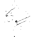
Figure 10 is, the stereographic map of another example of the existing optical head that is made of axle slidingtype twin shaft executive component.
This optical head shown in Figure 10 has coil rack 31, object lens 32, focusing coil 33, a pair of tracking coil 34a, 34b, tracking magnet 35a, 35c, focusing magnet 35b, 35d, tracking yoke 36a, 36c, focusing yoke 36b, 36d, back yoke 37a, 37b, axle 38 and counterbalance weight 39.
Focusing coil 33 installs around the periphery at coil rack 31, and tracking coil 34a, 34b are separately positioned on the two ends of the Y direction of coil rack 31.
Follow the tracks of to be provided with in opposite directions at the two ends of the Y direction of coil rack 31, be separately installed with tracking usefulness magnet 35a, 35c with the inboard of yoke 36a, 36c in this trackings with yoke 36a, 36c.Be provided with in opposite directions at the two ends of the X-direction of coil rack 31 with yoke 36b, 36d and focus on, be separately installed with focusing usefulness magnet 35b, 35d with the inboard of yoke 36b, 36d in this focusings.
In addition, back yoke 37a, 37b are provided with magnet 35b, 35d with focusing in opposite directions in the inboard of coil rack 31.
For this axle sliding-type optical head shown in Figure 10, when feeding electric current in focusing coil 33, coil rack 31 can move on Z-direction with respect to axle 38, and object lens 32 are moved on focus direction.And when feeding electric current in tracking coil 34a, 34b, coil rack 31 can be around axle 38 rotations, and object lens 32 are moved up the track side.
But, be the optical disk system of 120mm φ as disc size such as existing C D and DVD, from the viewpoint of setting up system, do not need to make the optical head miniaturization.In addition, even if minor diameter optical disk systems such as MD, the numerical aperture of object lens is not very big, thereby the distance between object lens and the CD is bigger, is not optical head must be received within the peristome of CD Pan Cang.Therefore, the miniaturization of optical head and unnecessary.
And on the other hand, though do not needing optical head is received within the peristome of CD Pan Cang, but come from the purpose that is used for portable set and have the occasion of miniaturization optical head, the dynamic property of the twin shaft executive component of this optical head can't adapt to high record density disk format of future generation.This be because, realize the high record densityization of CD, just need reduce to defocus and surplus that the road disperses, and, along with the raising of transfer rate, need make executive component have higher sensitivity, higher frequency range.
Owing to above reason, the twin shaft executive component of using for minor diameter high record density CD, be optical head, proposed the good requirement of compact in size and dynamic property, and can't satisfy these requirements with existing optical head.
That is to say, existing optical head shown in Figure 8, because of need with the perpendicular Y direction of the optical axis of object lens 15 on, configuration homopolarity magnet 20a, 20b in opposite directions, thereby can't realize miniaturization.
Existing optical head shown in Figure 9, though because of magnetic circuit configurations can realize miniaturization one-sided, but owing to comprise that the subresonance of the moving part of object lens and coil rack reduces and, performance is improved because of the difference of each position such as center of gravity, drive point, supporting-point causes dynamic property unbalanced.
And existing optical head shown in Figure 10, though can realize miniaturization, high performance, but, therefore, can't in defocusing the surplus small optical discs system that disperses with the road, use owing to having friction between axle and the skeleton axis hole and can't when carrying out small driving, guaranteeing linearity.
The present invention proposes in order to address the above problem, its objective is provides a kind of like this optical head, that is, easily realization can be received within it CD with the compact in size in the peristome of Pan Cang and realize the raising of the needed dynamic property of high density high transmission ratesization easily.
Summary of the invention
For achieving the above object, the present invention be a kind of drive object lens make it the Z of the focus direction perpendicular axle and CD with respect to optical disc surface radially, be the twin shaft executive component formula optical head that moves on the X-axis both direction of tracking direction, it is characterized in that, have: coil rack, this coil rack keeps said object lens and makes the optical axis of these object lens consistent with said Z axle; Focusing coil, this focusing coil is arranged on the said coil rack with the form of reeling around said Z axle; A pair of tracking coil, this a pair of tracking coil is at the two ends of the said X-direction of said coil rack, is provided with the form of reeling around X-axis; Elastic supporting part, this elastic supporting part supports and enables to swing on focus direction and tracking direction said coil rack; Two groups of magnet, these two groups of magnet are separately positioned on the position in opposite directions, two ends with perpendicular to said each tracking coil on the Y direction of said Z axle and X-axis, and are homopolarity each other being parallel to be magnetized on the direction of Y-axis with said tracking coil face in opposite directions; Magnetic circuit, this magnetic circuit have constituted can make said respectively organize among the magnet on X-direction said focusing coil is clipped in the middle and in opposite directions the magnetic line of force that pair of magnet produced passes the magnetic circuit of the closure of said tracking coil and focusing coil.
In optical head involved in the present invention, because two groups of magnet needn't be arranged on perpendicular to constituting the magnetic circuit that can produce driving force on tracking direction and focus direction on the Y-axis of the optical axis of object lens, therefore, can make the optical head size on Y direction, realize miniaturization.
And, because each organizes magnet is to become plane symmetry to be provided with respect to the Z axle at the optical axis place that comprises object lens and the Z-Y plane of Y-axis, and, being magnetized to tracking coil face in opposite directions on Y direction is that the magnet of homopolarity is to become plane symmetry to be provided with respect to the Z axle at the optical axis place that comprises object lens and the Z-X plane of X-axis, therefore, by making the center of gravity of the moving part that comprises coil rack and object lens etc., focus on (tracking) drive point and focusing (tracking) supporting-point and focusing on arrangement on (tracking) axle, the unbalanced of dynamic property can be prevented, the raising of the needed dynamic property of high density high transmission ratesization can be realized.
Description of drawings
Fig. 1 is the stereographic map of an embodiment of optical head involved in the present invention.
Fig. 2 is the stereographic map of coil rack, focusing coil and the tracking coil part of the related optical head of an embodiment of the present invention.
Fig. 3 is the key diagram of the Distribution of Magnetic Field of the related magnet of an embodiment of the present invention.
Fig. 4 is the stereographic map that the focusing coil in an embodiment of the present invention and tracking coil is described usefulness.
Fig. 5 is the synoptic diagram that the drive principle of the optical head in an embodiment of the present invention is described usefulness.
Fig. 6 is the stereographic map of optical head that another embodiment of back yoke among the present invention is showed.
Fig. 7 is the stereographic map of another embodiment of optical head involved in the present invention.
Fig. 8 is the stereographic map of an example of the existing optical head that is made of the open twin shaft executive component of magnetic circuit.
Fig. 9 is the stereographic map of another example of the existing optical head that is made of the twin shaft executive component of magnetic circuit closure.
Figure 10 is the stereographic map of another example of the existing optical head that is made of axle slidingtype twin shaft executive component.
Embodiment
Below, embodiments of the present invention are elaborated in conjunction with the accompanying drawings.
Fig. 1 is the stereographic map of an embodiment of optical head involved in the present invention, Fig. 2 is the stereographic map of coil rack, focusing coil and the tracking coil part of the optical head in the embodiment, Fig. 3 is the key diagram of the Distribution of Magnetic Field of the magnet in the embodiment, Fig. 4 is the stereographic map that the focusing coil in the embodiment and tracking coil is described usefulness, and Fig. 5 is the synoptic diagram that the drive principle of the optical head in the embodiment is described usefulness.
In Fig. 1 and Fig. 2, the 100th, radially be to move on the X-axis both direction of tracking direction by driving that object lens make it at the Z of the focus direction perpendicular axle and CD with respect to optical disc surface, thereby can be to the surface vibration and the eccentric twin shaft executive component formula optical head of following the trail of of CD, this optical head 100 has coil rack 101, object lens 102, a focusing coil 103, a pair of tracking coil 104a, 104b, 4 leaf spring 105a~105d (suitable) with the supporting device of claims, bearing support 106, two groups of 4 magnet 107a~107d, yoke 108a~108d corresponding to magnet 107a~107d, back yoke 109a, 109b.
Said object lens 102 are arranged on the central part of coil rack 101 with its optical axis state consistent with Z axle (focus direction).
Said focusing coil 103 with the perpendicular Y direction of Z axle and X-axis on rectangular shaped, this focusing coil 103 installs around periphery at coil rack 101 with the form of reeling around the Z axle.
Said tracking coil 104a, 104b are rectangular shape long on Z-direction, and this tracking coil 104a, 104b are in the form setting of the two ends of the X-direction of coil rack 101 to reel around X-axis.
Said 4 leaf spring 105a~105d have constituted the coil rack 101 that comprises object lens 102 grades are supported and enables supporting device in the swing of focus direction and tracking direction, the end of this leaf spring 105a~105d is connected on the two ends of X-direction of coil rack 101, and the other end is fixed on the bearing support 106.
In addition, leaf spring 105a~105d also double as supply with the signal wire that signal is used to focusing coil 103 and tracking coil 104a, 104b.
One group of magnet 107a, 107b among said magnet 107a~107d are as shown in figures 1 and 3, be separately positioned on the position in opposite directions, two ends with the Y direction of tracking coil 104a, and, another group magnet 107c, 107d are separately positioned on the position in opposite directions, two ends with the Y direction of tracking coil 104b as shown in figures 1 and 3.And this each magnet 107a~107d is installed in corresponding with them respectively and is parallel on yoke 108a~108d that the Z axle erect to be provided with.
In this occasion, magnet 107a and 107b as shown in Figure 3, on Y direction, be magnetized to tracking coil 104a face in opposite directions be homopolarity, for example N utmost point, and, magnet 107c and 107d as shown in Figure 3, on Y direction, be magnetized to tracking coil 104b face in opposite directions be homopolarity, for example N utmost point.In addition, each organizes magnet 107a~107d as shown in figures 1 and 3, is with respect to the Z-Y plane of the Z axle at the optical axis place that comprises object lens 102 and Y-axis and comprises that the Z axle at optical axis place of object lens 102 and the Z-X plane of X-axis become the plane symmetry setting.
Said back yoke 109a, 109b are in the both sides focusing coil 103 in opposite directions that probes into the Y direction of object lens 102 and are parallel to the Z axle and are provided with as shown in figures 1 and 3.
This back yoke 109a, among the 109b, back yoke 109a has constituted and focusing coil 103 has been clipped in the middle and the magnetic line of force of toward each other magnet 107a and 107d passes the coil side 103a of focusing coil 103 as illustrated in fig. 3, the closed magnetic circuit of the coil side 104a2 of 103b and tracking coil 104a and the coil side 104b2 of tracking coil 104b, and back yoke 109b constitutes and focusing coil 103 to be clipped in the middle and the magnetic line of force of toward each other magnet 107b and 107c passes the coil side 103a of focusing coil 103 as illustrated in fig. 3, the magnetic circuit of the closure of the coil side 104a1 of 103b and tracking coil 104a and the coil side 104b1 of tracking coil 104b.
In the optical head 100 that as above constitutes, realize by magnet 107a~107d, yoke 108a~108d and back yoke 109a, 109b, the distribution of magnetic field on focusing coil 103 and tracking coil 104a, 104b as shown in Figure 3.
Under this Distribution of Magnetic Field state, when as shown in Figure 5, when in tracking coil 104a, 104b, feeding electric current I t, because magnetic line of force 110a~110d passes coil side 104a1, the 104a2 of tracking coil 104a and coil side 104b1, the 104b2 of tracking coil 104b in vertical direction, thereby will produce driving force Ft on tracking direction.So, comprise that the object lens 102 of coil rack 101 grades will be activated on tracking direction under the effect of the driving force Ft sum that two tracking coil 104a, 104b are produced separately.
In addition, as shown in Figure 5, because the back yoke 109a of high permeability, the existence of 109b, as because of homopolarity toward each other two groups of magnet 107a~107d can with very high magnetic flux density and as the magnetic line of force that efficiently contain vertical composition pass coil side 103a, the 103b of focusing coil 103 to the magnetic line of force 113a, the 113b that produce in the other direction each other.Therefore, when in focusing coil 103, feeding electric current I f, will on focus direction, produce driving force Ff, comprise that the object lens 102 of coil rack 101 grades are activated on focus direction.In this occasion, because of the existence of back yoke 109a, 109b, magnetic circuit is closed magnetic circuit and constitutes, therefore, and its acceleration sensitivity height, but also can alleviate the focusing that is produced when producing skew on the tracking direction and follow the tracks of the unbalanced of driving force.
According to this optical head in the present embodiment, since two groups of magnet 107a~107d and yoke 108a~108d needn't be configured in the perpendicular Y-axis of the optical axis of object lens 102 on can constitute the magnetic circuit of the driving force that produces tracking direction and focus direction, therefore, can make the size of optical head on Y direction, realize miniaturization.Therefore, can be easy to realize folding and unfolding in the CD of recording density height and minor diameter less than 120mm φ dustproof with the compact optical head in the peristome of Pan Cang.
In addition, respectively magnet 107a~107d of group becomes plane symmetry to be provided with respect to the Z axle at the optical axis place that comprises object lens 102 and the Z-Y plane of Y-axis, and, being magnetized to tracking coil 104a face in opposite directions on Y direction is that the magnet 107a~107d of homopolarity becomes plane symmetry to be provided with respect to the Z axle at the optical axis place that comprises object lens 102 and the Z-X plane of X-axis, therefore, by making the center of gravity of the moving part that comprises coil rack 101 and object lens 102 etc., focus on (tracking) drive point and focusing (tracking) supporting-point and focusing on arrangement on (tracking) axle, the unbalanced of dynamic property can be prevented, the raising of the needed dynamic property of high density high transmission rates can be realized at an easy rate.
In the present invention, the vertical cube of back yoke 109a, 109b to, be not limited to shown in Figure 1, on Y direction, object lens 102 are clipped in the middle and the mode that stands vertically with respect to Y-axis.
For example, also can be as shown in Figure 6, make it to probe in the both sides focusing coil 103 in opposite directions with the X-direction of object lens 102 and be parallel to the setting of Z axle.
In Fig. 6, what the key element of representing with the numbering identical with Fig. 1 was represented is the component part identical with Fig. 1.
In addition, in the present invention, about the way that magnet produced, that use as the magnetic circuit of voice coil motor perpendicular to the magnetic field composition of direction of magnetization that will dispose in opposite directions by homopolarity, in Fig. 1, only be applied to focusing coil, but be not limited to this, according to its formation, also can be applied to tracking coil or be applied to tracking coil and focusing coil the two.
In addition, the supporting device in the twin shaft executive component formula optical head of the present invention is not limited to leaf spring mode illustrated in the above-mentioned embodiment, as long as can carry out elastic bearing to moving part, also can adopt forms such as hinge.
In addition, about back yoke 109a, the 109b in the above-mentioned embodiment, viewpoint from the repulsion that utilizes homopolarity magnet in opposite directions, and it is nonessential, particularly with regard to the dynamic property of executive component, compare the occasion that more lays particular emphasis on the raising frequency response range with acceleration sensitivity, back yoke effect is not set sometimes can be better.
The advantage that the back yoke is set is, thereby can improves magnetic flux density and reduce the opposite force raising acceleration sensitivity that leakage flux produces.Otherwise the advantage that the back yoke is not set is not need to be provided with the window that is intended to be provided with the back yoke owing on the coil rack 101, thereby the frequency range of the subresonance of moving part is improved.
Owing to above reason, can when needing to improve acceleration sensitivity the back yoke be set according to the situation of the optical disk system that adopts twin shaft executive component formula optical head, when needing disconnection (cutoff) that frequency range is improved the back yoke is not set, to satisfy its requirement.
Below, in conjunction with Fig. 7 another embodiment of optical head involved in the present invention is described.
Fig. 7 is the stereographic map of the optical head in another embodiment.In this Fig. 7, give identical numbering and it is constituted the explanation omission for the inscape identical with Fig. 1 and Fig. 6, attaching most importance to the part different with Fig. 1 and Fig. 6 describes.
Among this Fig. 7, be with the difference of Fig. 1 and Fig. 6, on coil rack 101, be provided with the liquid crystal device 112 that the aberration of object lens 102 is revised, and the driving that said liquid crystal device 112 is installed is with the driving of loop device and focusing coil 103 and tracking coil 104a, 104b flexible PCB 114a, the 114b with loop device (omitting among the figure), is separately positioned on two sides with the Y direction of the coil rack 101 of the Z-X plane parallel of the Z axle at the optical axis place that comprises object lens 102 and X-axis.
Record of direction shown in the arrow A that said liquid crystal device 112 is a side, for example Fig. 7 below object lens 102 or regeneration are arranged on the coil rack 101 with incident one side of light beam.
In addition, for the driving components and parts that are installed on flexible PCB 114a, the 114b, drive with control signal and focusing coil and tracking coil driving with control signal by 4 leaf spring 105a~105d to its supply from the liquid crystal device of the control part that has omitted among the figure.
In addition, the liquid crystal drive that is installed on flexible PCB 114a, the 114b is modulated the control signal of bringing by leaf spring 105a~105d with the loop device, and its modulation signal supplied with liquid crystal device 112 and liquid crystal device 112 is driven, thereby can revise the aberrations such as spherical aberration of object lens 102.Similarly, the coil drive that is installed on flexible PCB 114a, the 114b is modulated the control signal of bringing by leaf spring 105a~105d with the loop device, and its modulation signal supplied with focusing coil 103 or tracking coil 104a, 104b and these coils are carried out excitatory, thereby object lens 102 that can controlling packet vinculum ring framework 101 are gone up at focus direction (Z-direction) or tracking direction (X-direction) and are moved.
As the optical head in this embodiment, except accessing the effect identical with embodiment shown in Figure 6 with Fig. 1, because the driving that liquid crystal device 112 and focusing coil 103 and tracking coil 104a, 104b be installed is with flexible PCB 114a, the 114b of loop device etc., can be arranged on two sides with the Y direction of the coil rack 101 of Z-X plane parallel, thereby can also increase the components and parts erection space of flexible PCB.
In above-mentioned embodiment shown in Figure 7, the example that just flexible PCB 114a, 114b is arranged on two sides with the Y direction of the coil rack 101 of the Z-X plane parallel of Z axle at optical axis place that comprises object lens 102 and X-axis is illustrated, but the present invention is not limited to this, also can adopt with flexible PCB 114a, 114b be arranged on shown in Figure 7, with two sides of the X-direction of the coil rack 101 of the Z-Y plane parallel of the Z axle at the optical axis place that comprises object lens 102 and Y-axis on mode.
In addition, circuit board 114a, the 114b among the present invention is not limited to flexible PCB.
In addition, in embodiment shown in Figure 7, be illustrated with regard to liquid crystal device 112 example that a side is arranged on the coil rack 101 below object lens 102, but the present invention is not limited to this, also liquid crystal device 112 can be assembled in the optical system of object lens 102, can also be arranged on the record of object lens 102 or outgoing one side (top sides of object lens shown in Fig. 7 102) that light beam is used in regeneration.
As mentioned above, according to optical head of the present invention, be implemented in the folding and unfolding of minor diameter CD easily at the dustproof compact optical head of using in the peristome of Pan Cang, and center of gravity, focusing (tracking) drive point and focusing (tracking) supporting-point arrangement on focusing (tracking) axle by making the moving part that comprises coil rack and object lens etc., can prevent the unbalanced of dynamic property, realize the raising of the needed dynamic property of high density high transmission rates easily.
Claims (10)
- One kind can drive object lens make it the Z of the focus direction vertical axle and CD with respect to optical disc surface radially, be the twin shaft executive component formula optical head that moves on the X-axis both direction of tracking direction, it is characterized in that having:Coil rack, this coil rack keeps said object lens and makes the optical axis of these object lens consistent with said Z axle;Focusing coil, this focusing coil is arranged on the said coil rack with the form of reeling around said Z axle;A pair of tracking coil, this a pair of tracking coil is at the two ends of the said X-direction of said coil rack, is provided with the form of reeling around X-axis;Elastic supporting part, this elastic supporting part supports and enables to swing on focus direction and tracking direction said coil rack;Two groups of magnet, these two groups of magnet are separately positioned on the position in opposite directions, two ends with perpendicular to said each tracking coil on the Y direction of said Z axle and X-axis, and are homopolarity each other being parallel to be magnetized on the direction of Y-axis with said tracking coil face in opposite directions;Magnetic circuit, this magnetic circuit have constituted can make said respectively organize among the magnet on said X-direction said focusing coil is clipped in the middle and in opposite directions the magnetic line of force that pair of magnet produced passes the magnetic circuit of the closure of said tracking coil and focusing coil.
- 2. as the said optical head of claim 1, it is characterized in that said elastic supporting part is made of a plurality of leaf springs.
- 3. as the said optical head of claim 2, it is characterized in that said leaf spring double as is supplied with the signal wire that signal is used to said focusing coil and tracking coil.
- 4. as the said optical head of claim 1, it is characterized in that, said two groups respectively to organize magnet be with respect to the Z-Y plane of the Z axle at the optical axis place that comprises said object lens and Y-axis and comprise that the Z axle at optical axis place of said object lens and the Z-X plane of X-axis become plane symmetry to be provided with.
- 5. as the said optical head of claim 1, it is characterized in that said magnetic circuit has: with the corresponding respectively yoke of said two groups of magnet and probe in the both sides focusing coil in opposite directions with the Y direction of said object lens and be parallel to the back yoke that the Z axle is provided with.
- 6. as the said optical head of claim 1, it is characterized in that said magnetic circuit has: with the corresponding respectively yoke of said two groups of magnet and probe in the both sides focusing coil in opposite directions with the X-direction of said object lens and be parallel to the back yoke that the Z axle is provided with.
- 7. as the said optical head of claim 1, it is characterized in that said object lens have the liquid crystal device that the aberration of these object lens is revised.
- 8. as the said optical head of claim 1, it is characterized in that, with two sides of the X-direction of the said coil rack of the Z-Y plane parallel of the Z axle at the optical axis place that comprises said object lens and Y-axis and with at least one side of two sides of the Y direction of the said coil rack of the Z-X plane parallel of the Z axle at the optical axis place that comprises said object lens and X-axis on, be provided with driving that said focusing coil and tracking coil have been installed circuit board with the loop device.
- 9. as the said optical head of claim 1, it is characterized in that, said object lens have the liquid crystal device that the aberration of these object lens is revised, with two sides of the X-direction of the said coil rack of the Z-Y plane parallel of the Z axle at the optical axis place that comprises said object lens and Y-axis and with at least one side of two sides of the Y direction of the said coil rack of the Z-X plane parallel of the Z axle at the optical axis place that comprises said object lens and X-axis on, be provided with driving that said focusing coil and tracking coil and said liquid crystal device have been installed circuit board with the loop device.
- 10. as the said optical head of claim 1, it is characterized in that, said elastic supporting part is made of a plurality of leaf springs, said object lens have the liquid crystal device that the aberration of these object lens is revised, with two sides of the X-direction of the said coil rack of the Z-Y plane parallel of the Z axle at the optical axis place that comprises said object lens and Y-axis, and with at least one side of two sides of the Y direction of the said coil rack of the Z-X plane parallel of the Z axle at the optical axis place that comprises said object lens and X-axis on, be provided with said focusing coil and tracking coil have been installed, and the driving of the said liquid crystal device circuit board of loop device, said leaf spring double as is supplied with the signal wire that signal is used to said driving with circuit board.
Applications Claiming Priority (5)
| Application Number | Priority Date | Filing Date | Title |
|---|---|---|---|
| JP32405/2002 | 2002-02-08 | ||
| JP2002032405 | 2002-02-08 | ||
| JP130331/2002 | 2002-05-02 | ||
| JP2002130331A JP4085245B2 (en) | 2002-02-08 | 2002-05-02 | Optical head and optical disk apparatus |
| PCT/JP2003/001306 WO2003067583A1 (en) | 2002-02-08 | 2003-02-07 | Optical head |
Publications (2)
| Publication Number | Publication Date |
|---|---|
| CN1628345A CN1628345A (en) | 2005-06-15 |
| CN1311445C true CN1311445C (en) | 2007-04-18 |
Family
ID=27736463
Family Applications (1)
| Application Number | Title | Priority Date | Filing Date |
|---|---|---|---|
| CNB038034662A Expired - Fee Related CN1311445C (en) | 2002-02-08 | 2003-02-07 | Optical head |
Country Status (6)
| Country | Link |
|---|---|
| US (1) | US7196978B2 (en) |
| EP (1) | EP1473715A4 (en) |
| JP (1) | JP4085245B2 (en) |
| KR (1) | KR20040075103A (en) |
| CN (1) | CN1311445C (en) |
| WO (1) | WO2003067583A1 (en) |
Families Citing this family (7)
| Publication number | Priority date | Publication date | Assignee | Title |
|---|---|---|---|---|
| JPH0646347U (en) * | 1992-11-20 | 1994-06-24 | 日本特殊陶業株式会社 | Pressure sensor |
| JP2005317082A (en) * | 2004-04-28 | 2005-11-10 | Funai Electric Co Ltd | Optical pickup |
| JP2006065971A (en) * | 2004-08-27 | 2006-03-09 | Mitsumi Electric Co Ltd | Optical pickup |
| JP2008052865A (en) * | 2006-08-28 | 2008-03-06 | Funai Electric Co Ltd | Objective lens actuator and optical disk device |
| JP2008122594A (en) * | 2006-11-10 | 2008-05-29 | Konica Minolta Opto Inc | Lens driving device |
| TWI368098B (en) * | 2008-03-27 | 2012-07-11 | E Pin Optical Industry Co Ltd | Electromagnet for lens driving mechanism thereof |
| JP2012113780A (en) * | 2010-11-24 | 2012-06-14 | Hitachi Media Electoronics Co Ltd | Optical pickup |
Citations (5)
| Publication number | Priority date | Publication date | Assignee | Title |
|---|---|---|---|---|
| JPH07225960A (en) * | 1994-02-14 | 1995-08-22 | Nec Corp | Objective lens actuator and its manufacture |
| JPH10202281A (en) * | 1997-01-28 | 1998-08-04 | Maezawa Ind Inc | Waste water treating device |
| JPH11144270A (en) * | 1997-11-11 | 1999-05-28 | Fujitsu Ten Ltd | Optical pickup |
| JP2001266394A (en) * | 2000-03-17 | 2001-09-28 | Matsushita Electric Ind Co Ltd | Objective lens driving device |
| CN1384963A (en) * | 1999-10-27 | 2002-12-11 | 汤姆森特许公司 | Optical scanning device |
Family Cites Families (9)
| Publication number | Priority date | Publication date | Assignee | Title |
|---|---|---|---|---|
| JP2798719B2 (en) * | 1989-08-15 | 1998-09-17 | オリンパス光学工業株式会社 | Optical system support device |
| JP3125105B2 (en) | 1991-10-31 | 2001-01-15 | 株式会社リコー | Objective lens drive |
| JPH05342605A (en) | 1992-06-09 | 1993-12-24 | Matsushita Electric Ind Co Ltd | Driving device for objective lens |
| JP3834831B2 (en) * | 1995-03-20 | 2006-10-18 | ソニー株式会社 | Objective lens driving device and optical pickup device using the objective lens driving device |
| JPH0916996A (en) * | 1995-06-30 | 1997-01-17 | Sony Corp | Biaxial actuator |
| JPH10302281A (en) | 1997-04-30 | 1998-11-13 | Toshiba Corp | Optical head |
| JP4067646B2 (en) | 1998-07-03 | 2008-03-26 | スタンレー電気株式会社 | Discharge lamp lighting device |
| JP2001331956A (en) | 2000-03-13 | 2001-11-30 | Matsushita Electric Ind Co Ltd | Objective lens driving device |
| JP2003006902A (en) | 2001-06-18 | 2003-01-10 | Sony Corp | Optical pickup |
-
2002
- 2002-05-02 JP JP2002130331A patent/JP4085245B2/en not_active Expired - Fee Related
-
2003
- 2003-02-07 CN CNB038034662A patent/CN1311445C/en not_active Expired - Fee Related
- 2003-02-07 US US10/501,717 patent/US7196978B2/en not_active Expired - Fee Related
- 2003-02-07 KR KR10-2004-7011368A patent/KR20040075103A/en not_active Application Discontinuation
- 2003-02-07 EP EP03703254A patent/EP1473715A4/en not_active Withdrawn
- 2003-02-07 WO PCT/JP2003/001306 patent/WO2003067583A1/en active Application Filing
Patent Citations (5)
| Publication number | Priority date | Publication date | Assignee | Title |
|---|---|---|---|---|
| JPH07225960A (en) * | 1994-02-14 | 1995-08-22 | Nec Corp | Objective lens actuator and its manufacture |
| JPH10202281A (en) * | 1997-01-28 | 1998-08-04 | Maezawa Ind Inc | Waste water treating device |
| JPH11144270A (en) * | 1997-11-11 | 1999-05-28 | Fujitsu Ten Ltd | Optical pickup |
| CN1384963A (en) * | 1999-10-27 | 2002-12-11 | 汤姆森特许公司 | Optical scanning device |
| JP2001266394A (en) * | 2000-03-17 | 2001-09-28 | Matsushita Electric Ind Co Ltd | Objective lens driving device |
Also Published As
| Publication number | Publication date |
|---|---|
| JP2003303430A (en) | 2003-10-24 |
| WO2003067583A1 (en) | 2003-08-14 |
| JP4085245B2 (en) | 2008-05-14 |
| EP1473715A1 (en) | 2004-11-03 |
| KR20040075103A (en) | 2004-08-26 |
| US7196978B2 (en) | 2007-03-27 |
| US20050128893A1 (en) | 2005-06-16 |
| EP1473715A4 (en) | 2007-07-25 |
| CN1628345A (en) | 2005-06-15 |
Similar Documents
| Publication | Publication Date | Title |
|---|---|---|
| CN1214369C (en) | Driver for optical pick-up device | |
| CN1194342C (en) | Actuator of optical pick-up device | |
| CN1311445C (en) | Optical head | |
| CN101022017A (en) | Object lens drive unit | |
| CN1516135A (en) | Objective lens drive device and optical pickup device | |
| CN100407302C (en) | Optical pick device | |
| CN1161762C (en) | Double-shaft regulator, optical parts and light disk device | |
| CN100345194C (en) | 3d actuator for optical disc system | |
| CN100472617C (en) | Optical pickup actuator and optical recording and/or reproducing apparatus | |
| CN1658301A (en) | Optical pick-up apparatus with lenses | |
| CN1710647A (en) | Objective lens driving apparatus and optical disk apparatus | |
| CN101677003B (en) | Objective lens actuator and an optical pickup | |
| CN100372002C (en) | Slim type optical pick-up actuator | |
| CN100419877C (en) | Optical pickup actuator and optical recording and/or reproducing apparatus having the same | |
| US7453656B2 (en) | Recording and/or reproducing apparatus with an optical pickup actuator having high thrust | |
| CN1201307C (en) | Optical mechanism driving device | |
| CN1794348A (en) | Optical pickup actuator and optical recording/reproducing apparatus | |
| CN1192612C (en) | Disk recording apparatus for video camera | |
| CN1794349A (en) | Optical pickup actuator and optical recording and/or reproducing apparatus | |
| CN1497550A (en) | Objective lens drive device and optical disk device | |
| CN1606078A (en) | Actuator of optical pick-up device | |
| CN100545925C (en) | Light picker | |
| CN1684163A (en) | Optical pickup actuator and optical recording and/or reproducing apparatus | |
| CN100419875C (en) | Switcher of optical pickup excitor | |
| CN1963924A (en) | Exciter and optical disc driver |
Legal Events
| Date | Code | Title | Description |
|---|---|---|---|
| C06 | Publication | ||
| PB01 | Publication | ||
| C10 | Entry into substantive examination | ||
| SE01 | Entry into force of request for substantive examination | ||
| C14 | Grant of patent or utility model | ||
| GR01 | Patent grant | ||
| C17 | Cessation of patent right | ||
| CF01 | Termination of patent right due to non-payment of annual fee |
Granted publication date: 20070418 Termination date: 20100207 |