CN1311289C - Lmage display system - Google Patents
Lmage display system Download PDFInfo
- Publication number
- CN1311289C CN1311289C CNB028035631A CN02803563A CN1311289C CN 1311289 C CN1311289 C CN 1311289C CN B028035631 A CNB028035631 A CN B028035631A CN 02803563 A CN02803563 A CN 02803563A CN 1311289 C CN1311289 C CN 1311289C
- Authority
- CN
- China
- Prior art keywords
- light
- display system
- image
- image display
- display device
- Prior art date
- Legal status (The legal status is an assumption and is not a legal conclusion. Google has not performed a legal analysis and makes no representation as to the accuracy of the status listed.)
- Expired - Fee Related
Links
Images


Classifications
-
- G—PHYSICS
- G03—PHOTOGRAPHY; CINEMATOGRAPHY; ANALOGOUS TECHNIQUES USING WAVES OTHER THAN OPTICAL WAVES; ELECTROGRAPHY; HOLOGRAPHY
- G03B—APPARATUS OR ARRANGEMENTS FOR TAKING PHOTOGRAPHS OR FOR PROJECTING OR VIEWING THEM; APPARATUS OR ARRANGEMENTS EMPLOYING ANALOGOUS TECHNIQUES USING WAVES OTHER THAN OPTICAL WAVES; ACCESSORIES THEREFOR
- G03B21/00—Projectors or projection-type viewers; Accessories therefor
- G03B21/10—Projectors with built-in or built-on screen
Landscapes
- Physics & Mathematics (AREA)
- General Physics & Mathematics (AREA)
- Projection Apparatus (AREA)
- Devices For Indicating Variable Information By Combining Individual Elements (AREA)
- Lenses (AREA)
- Transforming Electric Information Into Light Information (AREA)
- Overhead Projectors And Projection Screens (AREA)
Abstract
The present invention provides an image display system, comprising an illuminating light source system formed of a light emitting body, a parabolic mirror (12), and a condensing lens (13); a transmission means (10) having a light valve (14) for injecting light coming from the illuminating light source system after receiving image information; a projection optical means (20) having a refractive optical lens (21) for projecting the light from the transmission means (10) and a convex mirror (22) for extendedly projecting by reflecting the light from the refractive optical lens (21) by a reflective surface with a negative power; and a display means (30) for receiving the light from the projection optical means (20) by a light receiving surface (30A) and displaying images based on the image information on an image display surface (30B), wherein the transmission means (10) is disposed between the front face of the display means (30) and the rear face of the projection optical means (20) at a position out of the optical axis (23) of the projection optical means (20).
Description
Technical field
The light that the present invention relates to have image information from the back side to the display device enlarging projection and the image display system of display image.
Background technology
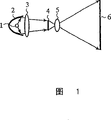
Fig. 1 is a structural map of representing image display system in the past.
At Fig. 1, the 1st, send the luminophor of light, the 2nd, the light that self-luminous body 1 is sent is reflected into and roughly becomes parallel paraboloidal mirror, and the 3rd, the collector lens of the light optically focused that paraboloidal mirror 2 is reflected.Luminophor 1, paraboloidal mirror 2 and collector lens 3 constitute lighting source system.
The 4th, the light of collector lens 3 being assembled according to image information is the light valve of modulate intensity spatially, and the 5th, will utilize light valve 4 to modulate the projection optics lens of the optical projection of intensity, the 6th, the light from 5 projections of projection optical lens is shown as the screen of image.Light path is represented with arrow.
Secondly explanation action.
After light polished object face mirror 2 reflections that self-luminous body 1 sends, utilize collector lens 3 to light valve 4 optically focused.Light valve 4 according to image information with the light assembled modulate intensity spatially.Light after the modulate intensity utilizes projection optics lens 5, and (left of Fig. 1) is shown as image to screen 6 projections from the rear.The user of image display system looks from the place ahead (Fig. 1's is right-hand) of the screen 6 of Fig. 1 and recognizes image.
It is distance till the screen 6 that the degree of depth of the image display system of Fig. 1 is equivalent to from the lighting source that is made of luminophor 1, paraboloidal mirror 2 and collector lens 3.If but the image display system of the identical image of display size makes the described degree of depth better thin as far as possible textural.Because this reason, at image display system in the past shown in Figure 1, but the slimming for the degree of depth that suppresses image display system as far as possible uses the projection optics lens 5 of wide-angle that image is shown in screen 6.
; because of the wide-angle of projection optics lens 5 restricted, for more slimming of image display system, as shown in Figure 2 with Fig. 1; in textural setting with respect to tilt 45 ° level crossing 7 of horizontal direction, will from after the light path bending of projection optical lens 5 to screen 6 projections.
At the image display system of Fig. 2,, but make the image display system slimming at each composed component of the short transverse (above-below direction of Fig. 2) of image display system configuration lighting source system or light valve 4, projection optics lens 5.Be equivalent to from the distance of level crossing 7 till the screen 6 in the degree of depth of the image display system of this situation.Make level crossing 7 with respect to the inclination of horizontal direction during greater than 45 °, can be with more slimming of image display system, but light valve 4 and the Lights section and projected light interfere, light becomes shade, light path departs from screen 6.
Again, the level crossing 7 in that the spy opens flat 6-11767 communique public use convex mirror alternate figures 2 with the image display system of image enlarging projection in screen 6, still shows the image of distortion behind the reflected light at screen 6.
Because of in the past image display system formation as noted above, be restricted in the slimming of image display system, have the further problem of slimming.
Summary of the invention
The present invention is for solving the above problems a little, and its purpose is to provide a kind of image display system, suppresses the distortion of image, and is capable of enlarged displaying, and with compared more slimming in the past.
Image display system of the present invention comprises: dispensing device applies illumination light and sends as the light image signal in image information; Projecting optical device is by the refract light department of the Chinese Academy of Sciences of the described light image signal projection that will send from described dispensing device and will constitute from the reflecting part of the described light image signal reflex of institute of described refract light department of the Chinese Academy of Sciences projection; And display device, accept described light image signal by described projecting optical device, show image according to described image information; Make position configuration dispensing device at the optical axis that departs from described projecting optical device, and between the back side of the front of display device and projecting optical device, dispose dispensing device.
Thereby, obtain providing effect than the image display system of slimming in the past.
Image display system of the present invention comprises: dispensing device applies illumination light and sends as the light image signal in image information; Projecting optical device is by will and constituting from the reflecting part of the described light image signal reflex of institute of described refract light department of the Chinese Academy of Sciences projection from the refract light department of the Chinese Academy of Sciences of the described light image signal projection that described dispensing device sent; And display device, accept described light image signal by described projecting optical device after, show image according to described image information; Make described dispensing device be disposed at the surface level below of the optical axis that comprises described projecting optical device, and described display device configurations is in the surface level top of the optical axis that comprises described projecting optical device.
Thereby, obtain providing than the effect of the image display system of slimming more in the past.
The present invention also comprises:
A kind of image display system comprises:
Dispensing device offers illumination light to image information and sends as the light image signal;
Projecting optical device is made of the refract light department of the Chinese Academy of Sciences and reflecting part, and described reflecting part and this shared optical axis of refract light department of the Chinese Academy of Sciences will be from the described light image signal reflexs of institute of described refract light department of the Chinese Academy of Sciences projection; And
Display device makes the sensitization of described light image signal by described projecting optical device, shows the image based on described image information;
Described dispensing device is disposed at the position of the optical axis that departs from described projecting optical device, and is disposed between the back side of the front of described display device and described projecting optical device.
Description of drawings
Fig. 1 is a structural map of representing image display system in the past.
Fig. 2 is the structural map that expression is provided with the image display system in the past of level crossing.
Fig. 3 is the structural map of the image display system of expression embodiments of the invention 1.
Fig. 4 is the structural map of the image display system of expression embodiments of the invention 2.
Fig. 5 is the figure in order to the configuration condition of the first light path curved reflectors of the image display system of explanation embodiments of the invention 3.
Fig. 6 is the skeleton view of structure of the display device of the expression image display system that is applied to embodiments of the invention 4.
Fig. 7 is that the phenanthrene that is illustrated in display device is pinched the section shape figure of the refractive prism portion of ear lens formation.
Fig. 8 is that the phenanthrene that is illustrated in display device is pinched the section shape figure of the fully-reflected type prism portion of ear lens formation.
Fig. 9 is that the phenanthrene that is illustrated in display device is pinched the section shape figure of the hybrid type prism portion of ear lens formation.
Figure 10 is the figure in order to explanation action example of fan's light of generation multiple imaging on picture display face.
Figure 11 is the section shape figure that the phenanthrene of display device that expression is applied to the image display system of embodiments of the invention 5 is pinched the ear lens.
Figure 12 is the section shape figure that the phenanthrene of display device that expression is applied to the image display system of embodiments of the invention 5 is pinched the ear lens.
Figure 13 is the pattern figure that is illustrated in the stromatolithic structure of the light-transmitting layer of fan's light absorption plate and light absorbing zone.
Figure 14 is the section shape figure that the phenanthrene of display device that expression is applied to the image display system of embodiments of the invention 5 is pinched the ear lens.
Embodiment
Below, in order to be described in more detail the present invention, most preferred embodiment of the present invention is described according to additional drawing.
Fig. 3 is the structural map of the image display system of expression embodiments of the invention 1, is the sectional structural map that lateral surface is seen.Utilize arrow to represent light path.
Image display system at Fig. 3, the 10th, ejaculation has the dispensing device of the light (light image signal) of image information, the 20th, with projecting optical device from the light amplification projection that sends device 10, the 30th, accept from the display device that shows behind the light of projecting optical device 20 according to the image of image information.
Dispensing device 10 at Fig. 3, the 11st, send the luminophor of light, the 12nd, the light reflection of the set luminophor 11 of the focus of comfortable dispensing device 10 in the future and roughly become the paraboloidal mirror of directional light, the 13rd, the collector lens of the directional light optically focused that paraboloidal mirror 12 is reflected.Luminophor 11, paraboloidal mirror 12 and collector lens 13 constitute lighting source system.
Again, at the dispensing device 10,14th of Fig. 3, the light valve (light gate device) that penetrates after light (illumination light) modulate intensity of collector lens 13 being assembled according to image information.At Fig. 3, the optical modulation element of reflection-type is made as light valve 14, but the present invention can be applicable to the image display system that has comprised all optical modulation elements of liquid crystal of transmission-type for example etc.Again, the light valve 14 of dispensing device 10 is that any of the non-illumination mode of autoluminescence mode all can.
At the projecting optical device 20,21st of Fig. 3, dioptrics lens (the refract light department of the Chinese Academy of Sciences), the 22nd, convex mirror (reflecting part).In order to reduce the distortion aberration, use aspherical shape at dioptrics lens 21 or convex mirror 22, or make dioptrics lens 21 have the distortion aberration or the curvature of the image of offsetting separately in order to the distortion aberration or the curvature of the image of convex mirror 22 generations.
Again, at the projecting optical device 20,23rd of Fig. 3, the optical axis of projecting optical device 20.At the example of Fig. 3, dioptrics lens 21, convex mirror 22 shared optical axises 23.At present embodiment 1, departing from the position configuration dispensing device 10 of optical axis 23, and on the plane that comprises picture display face 30B (front of display device 30) of display device 30 with comprise configuration dispensing device 10 between the plane (back side of projecting optical device 20) of the back side 22B that comprises convex mirror 22 of projecting optical device 20.At this, the back side of the front of display device 30 and projecting optical device 20 is benchmark with the image display system, and display device 30 sides become the front.Surface level with the optical axis 23 that comprises projecting optical device 20 is a boundary, and dispensing device 10 is disposed at the below of surface level, display device 30 is disposed at the top of surface level.That is, at the rear side oblique upper configuration projecting optical device 20 of dispensing device 10, in the front face side oblique upper configuration display device 30 of projection optics 20.
In the display device 30 of Fig. 3,30A is the light-sensitive surface of display device 30, and 30B is the picture display face of the rectangular shape of display device 30, pinches ear lens 31 and biconvex lens 32 constitutes display device 30 by phenanthrene.Display device 30 utilizes the luxuriant and rich with fragrance prism portion almost parallel of pinching each spacing of ear lens 31 to penetrate to biconvex lens 32 behind the light of light-sensitive surface 30A acceptance from convex mirror 22.Biconvex lens 32 spreads after making phenanthrene pinch the ejaculation photoimaging of ear lens 31, and image is shown in picture display face 30B.About the detailed description of display device 30, will be in embodiment 3 explanations.
At present embodiment 1, make the reflecting surface (image outgoing plane) of light valve 14 and the light-sensitive surface 30A almost parallel of display device 30, the degree of depth of being arranged to image display system becomes the most shallow.Again, be configured to light valve 14 and display device 30 is not overlapping, the shade of light that makes no projection in short transverse.In addition, configuration projecting optical device 20 makes under the configuration condition that satisfies light valve 14 and display device 30, keeps the conjugate relation of light valve 14 and display device 30.
Secondly explanation action.
After light polished object face mirror 12 reflections that self-luminous body 11 sends, inject from tilted direction to the reflecting surface of light valve 14 by collector lens 13.Light valve 14 according to image information with modulate intensity rear orientation projection optical devices 20 reflections spatially of the light injected.Light valve 14 can be with the optical modulation intensity back reflection of injecting from tilted direction with respect to its reflecting surface because of being the optical modulation element of reflection-type.
At projecting optical device 20, dioptrics lens 21 are accepted after sending the light that device 10 goes into respect to optical axis 23 oblique fires, with light to convex mirror 22 projections.As shown in Figure 3, the optical axis 23 of dioptrics lens 21 is with respect to the reflecting surface of light valve 14 and the light-sensitive surface 30A approximate vertical of display device 30, and is arranged to and the center of light valve 14 and the center-biased of display device 30.Therefore, only the part of the image angle of dioptrics lens 21 is used for projection from the light of light valve 14.At Fig. 3, to inject from the below of dioptrics lens 21 because of light, light penetrates upward.
Convex mirror 22 utilizes the reflecting surface with negative power that light image is reflected the back to display device 30 enlarging projections.Cause is gone into respect to optical axis 23 oblique fires from the light of dispensing device 10, and the core of convex mirror 22 reflectings surface is not used for the projection to display device 30.Behind the light of display device 30 usefulness light-sensitive surface 30A acceptance from convex mirror 22, image is shown in picture display face 30B.
So, respectively at configuration display device up and down 30, the dispensing device 10 of the surface level of the optical axis 23 that comprises projecting optical device 20, the configuration dispensing device 10 that staggers with the optical axis 23 of projecting optical device 20, light from dispensing device 10 goes out to projecting optical device 20 oblique fires with respect to optical axis 23, from the light of projecting optical device 20 with respect to optical axis 23 to display device 30 oblique projections.Therefore, the light toward display device 30 becomes in the space of the part of image display system inside and repeats advancing of (shared) toward the light of convex mirrors 22 with from convex mirror 22 to send device 10 certainly, can effectively utilize limited space.
At this moment, for the thinness with image display system is suppressed at distance from the back side to the front of display device 30 of projection optical devices 20, will be in the space between the front (plane that comprises picture display face 30B) of the back side (plane that comprises the back side 22B of convex mirror 22 in the situation of Fig. 3) of projecting optical device 20 and display device 30, and the space of staggering with optical axis 23 is as the allocation position of dispensing device 10.In view of the above, comparable in the past with more slimming of image display system.Certainly, the configuration of dispensing device 10 makes the lower height of image display system can not uprise.Again,, display device 30 is disposed at above the surface level of the optical axis 23 that comprises projecting optical device 20 because of dispensing device 10 being disposed at the surface level below of the optical axis 23 that comprises projecting optical device 20, comparable in the past with more slimming of image display system.
As shown above, if according to present embodiment 1, comprise dispensing device 10, the light reflection of sending and show paraboloidal mirror 12 that directional light penetrates greatly, will and apply the light that image information assembled in collector lens 13 from the collector lens 13 of the directional light optically focused of paraboloidal mirror 12 and the light valve 14 that penetrates constitutes by the luminophor that sends light, with self-luminous body 11; Projecting optical device 20 is by will constituting from the convex mirror 22 of enlarging projection after the light reflection of dioptrics lens 21 from the dioptrics lens 21 of the optical projection that sends device 10, the reflecting surface that utilization has negative power; And display device 30, accept from being shown in picture display face 30B based on the image of image information behind the light of projecting optical device 20 with light-sensitive surface 30A; Because of making the position configuration dispensing device 10 that staggers at optical axis 23 with projecting optical device 20, and between the back side of the front of display device 30 and projecting optical device 20 configuration dispensing device 10, can obtain providing effect than the image display system of slimming in the past.
Again, if according to present embodiment 1, comprise dispensing device 10, the light reflection of sending by the luminophor that sends light, with self-luminous body 11 and show greatly paraboloidal mirror 12 that directional light penetrates, will be from the collector lens 13 of the directional light optically focused of paraboloidal mirror 12 and apply the light valve 14 that light that collector lens 13 assembled penetrates after image information; Projecting optical device 20 is by will constituting from the convex mirror 22 of enlarging projection after the light reflection of dioptrics lens 21 from the dioptrics lens 21 of the optical projection that sends device 10, the reflecting surface that utilization has negative power; And display device 30, accept from being shown in picture display face 30B based on the image of image information behind the light of projecting optical device 20 with light-sensitive surface 30A; Cause makes at the surface level downside configuration dispensing device 10 of the optical axis 23 that comprises projecting optical device 20, in the surface level upside of the optical axis 23 that comprises projecting optical device 20 configuration display device 30, can obtain to provide than the effect of the image display system of slimming more in the past.
In addition, if according to present embodiment 1,, can obtain to carry out easily the effect of the aligning adjustment of projecting optical device 20 and display device 30 because of making and the optical axis 23 of projecting optical device 20 roughly disposes display device 30 orthogonally.
In addition, if according to present embodiment 1,, can obtain being shown in effect on the picture display face 30B with alleviating warp image because of the reflecting surface (image outgoing plane) and the display device 30 of the light valve 14 of formation dispensing device 10 being configured to almost parallel each other.
At embodiment 2, the image display system that comprises at least one light path bending apparatus on the light path of device 10 till the display device 30 sending certainly is described.
Fig. 4 is the structural map of the image display system of expression embodiments of the invention 2, is the sectional structural map of seeing from the side.Pay identical symbol for the structure identical or suitable with Fig. 3.Utilize arrow to represent light path.
At Fig. 4,24,25 each naturally as first, second light path curved reflectors (projecting optical device) of light path bending apparatus.At this, from the light path of dioptrics lens 21 till the convex mirror 22 and on the light path of convex mirror 22 till the display device 30 light path curved reflectors 24, light path curved reflectors 25 being set separately.In addition, make when the normal line vector n1 of the past light path reflection direction of light path curved reflectors 25 and the optical axis 23 that comprises projecting optical device 20 and the plane almost parallel (light path curved reflectors 25 and display device 30 be configured to each other almost parallel) parallel, more the composing images display system of slimming with the following 30C of the picture display face 30B of display device 30.
At Fig. 4, in downside, each self-configuring dispensing device 10 of upside, the display device 30 of the surface level of the optical axis 23 that comprises projecting optical device 20.Again, convex mirror 22 roughly just on configuration display device 30, make unglazed shade, back side 24B, the 25B of light path curved reflectors 24,25 are disposed on the roughly common plane.In addition, the back side 22B of convex mirror 22 and picture display face 30B are positioned on the common plane.
Structure at embodiment 1, decide according to the back side 22B of convex mirror 22 at the back side of projecting optical device 20, but, at present embodiment 2, because of the back side 22B of convex mirror 22 towards with picture display face 30B the same side mutually, can not become the back side of projecting optical device 20, according to the plane of the back side 24B of the light path curved reflectors 24 that comprises the direction that court is opposite with picture display face 30B or comprise the back side of plane decision projecting optical device 20 of the back side 25B of light path curved reflectors 25.The configuration dispensing device 10 that between the back side of described projecting optical device 20 and the front of display device 30 (plane that comprises picture display face 30B), staggers with optical axis 23.
Secondly explanation action.
The light that penetrates from dioptrics lens 21 reflects successively and advances to light path curved reflectors 24, convex mirror 22, light path curved reflectors 25, display device 30.At this moment, respectively from light path curved reflectors 24 toward convex mirrors 22, repeat (shared) in the space of the part of image display system inside and advance toward light path curved reflectors 25, light from light path curved reflectors 25 toward display device 30 from convex mirror 22, can than the little space of the situation of Fig. 3 with light to display device 30 projections.That is, as shown in Figure 4, by light path curved reflectors 24,25 is set, but the image display system volume inside of more efficient use Fig. 4.
Therefore, the image display system of present embodiment 2, in the measure-alike situation of the picture display face 30B of display device 30, comparable embodiment 1 is the formation of slimming more, again in the identical situation of the thinness of image display system, can show the image bigger at picture display face 30B than embodiment 1.
In addition, in the situation that light path bending apparatus such as light path curved reflectors 24,25 is applied to image display system, utilize the inner space configuration of image display system cleverly, make the shade that light can not take place because of the light path bending apparatus, and the thinness of image display system or its underpart height can not become big.
At Fig. 4, be illustrated in the structure example of using light path curved reflectors 24,25 on the light path bending apparatus, but do not limit the allocation position of light path bending apparatus on light path especially again.For example, in situation about constituting, also can in the internal configurations light path curved reflectors 24 of dioptrics lens 21 by the multi-disc lens.
In addition, the number of light path bending apparatus does not limit especially yet.For example, though the diagram of omission, when being configured in from light path curved reflectors 25 of Fig. 4 appended the 3rd light path curved reflectors on the light path toward display device 30, from the light of light path curved reflectors 25 by the reflection of the 3rd light path curved reflectors after, advance to display device 30.
Therefore, light from light path curved reflectors 25 toward the 3rd light path curved reflectors and from the 3rd light path curved reflectors the light toward display device 30 repeats and advances at segment space, the image display system that can constitute more slimming maybe can show the image display system of bigger image.
Situation in above explanation, according to the plane of the back side 22B of the convex mirror 22 that comprises the direction that court is opposite with picture display face 30B or comprise the 3rd light path curved reflectors the back side plane decision projecting optical device 20 the back side (because of the plane of the back side 24B, the 25B that comprise light path curved reflectors 24,25 towards with picture display face 30B the same side mutually, can not become the back side of projecting optical device 20), at the back side of projecting optical device 20 with comprise that dispose dispensing device 10 with optical axis 23 between the plane (front of display device 30) of picture display face 30B gets final product with staggering.So the back side of projecting optical device 20 changes according to the allocation position of convex mirror 22 or light path bending apparatus or number and structure.
In addition, the light path bending apparatus is not defined as level crossing, in order to improve the degree of freedom for the design of light, follows the trail of and can work hard in its optic shape according to light path, or use the optical element beyond the level crossing can yet.By this, can carry out finer and close light control.For example, use will from the light of projection optical devices 20 to second projecting optical device (dioptrics lens and convex mirror) the instead of optical curved way catoptron 25 of display device 30 reflections also can, on the light path bending apparatus, use prism instead of optical curved way catoptron 24,25 also can.
As shown above, if according to present embodiment 2, because of making projecting optical device 20 to the light path of display device 30, comprise light path curved reflectors 24,25 sending device 10 certainly, can more effectively utilize image display system volume inside leaded light, obtain to provide the effect of the image display system of more slimming.
Again, if according to present embodiment 2, because of make towards the normal line vector n1 of the past light path reflection direction of light path curved reflectors 25 and the optical axis 23 that comprises projecting optical device 20 and also with the following parallel plane almost parallel of the picture display face 30B of display device 30, can obtain providing the effect of the image display system of more slimming.
At embodiment 3, for the lower height both sides of the thinness image display system that makes image display system as far as possible little, explanation utilizes in the light path curved reflectors of being inserted between dioptrics lens 21 and the convex mirror 22 24 makes the surface level that is comprising optical axis 23 the light path bending for the relativity configuration condition at the convex mirror 22 of first light path curved reflectors 24 shown in the embodiment 2 and dioptrics lens 21.
Fig. 5 is the figure in order to the configuration condition of the first light path curved reflectors of the image display system of explanation embodiments of the invention 3.Fig. 5 (a) and Fig. 5 (b) each side view and vertical view naturally, Fig. 5 (c) is the front elevation of convex mirror 22.For paying identical symbol with Fig. 3,4 identical or suitable structures.At Fig. 5, the optical axis of dioptrics lens 21 when 23Z is configuration light path curved reflectors 24,21 ' be the dioptrics lens that imagination is taken away the optical axis 23 that makes convex mirror 22 after the light path curved reflectors 24 situation consistent with optical axis 23Z.
Again, from the convex mirror of the image display system that convex mirror 22 is set the distance of face (reflecting part is provided with face) till the position (point of crossing of optical axis 23 and optical axis) of light path curved reflectors 24 being set is b, the point that will be in the point on the cross spider of surface level that comprises optical axis 23Z and dioptrics lens 21 near convex mirror face be set is called closest approach, to face point farthest be set from convex mirror and be called the solstics, distance till closest approach to convex mirror is provided with face is a, and the distance till solstics to convex mirror is provided with face is c.Distance c becomes from convex mirror the longest distance of face till the light path curved reflectors 24 is set.
In addition, establish from the peak of light path curved reflectors 24 height to optical axis 23 be m, certainly put distance till Q is provided with face to convex mirror be g, from dioptrics lens 21 ' the distance of ejaculation pupil position till to convex mirror face being set be f.Become from convex mirror apart from g the longest distance of face till the dioptrics lens 21 is set.Therefore, from dioptrics lens 21 ' ejaculation pupil position to the position of light path curved reflectors 24 till distance and total distance of the distance of the horizontal direction till position to the convex mirror of light path curved reflectors 24 is provided with face also become f.
Learn by Fig. 5 (a), be with from the lower height of the distance till the optical axis 23 bottom of display device 30 the shortizationest, order toward the reflection ray Lr of the convex mirror bottom 22 of display device 30 by more favourable near the lower position of optical axis 23 as far as possible.And in addition, if light path was passed through low position, light path is covered by light path curved reflectors 24 and become shade on display device 30, and the part that generation can't show can't be practical.Therefore, must determine the size positions of light path curved reflectors 24, make light path curved reflectors 24 not cover toward the reflection ray of the convex mirror bottom 22 of display device 30.
About the position of light path curved reflectors 24,, make long as far as possible apart from a for the reflection ray that makes convex mirror 22 passes through in the low light path of trying one's best.In addition,, because of being arranged, the thinness limits value by the specification decision of slimming distance c need be made as below the described thinness limits value in the thinness of image display system.
Under the situation of above condition with the light path bending, apart from f too in short-term, the part that comprises the some P of dioptrics lens 21 just covers from the light of light path curved reflectors 24 till the convex mirror 22.Or the part that is set as the some P that comprises dioptrics lens 21 do not cover when the light of light path curved reflectors 24 till convex mirror 22, becomes the weak point that exceeds needs apart from a.And, when oversize apart from f, condition according to the position of the light-sensitive surface of convex mirror 22 or light path curved reflectors 24, the position of dioptrics lens 21 exceed needs away from light path curved reflectors 24, the result, it is big that light path curved reflectors 24 becomes, and the value of the height m of light path curved reflectors 24 must be become big, just covers the reflection ray Lr bottom toward display device 30 from convex mirror 22 reflection backs.Thereby there is optimum value in f in distance.
About bending angle θ, learn by Fig. 5 (b), bending angle θ is made as when too big, just surpass the thinness limits value apart from g or distance c, and shorten apart from a, become and improve toward display device 30 height bottom from the reflection ray of convex mirror 22.
Otherwise if bending angle θ is diminished, because of distance g or distance c also shorten, dioptrics lens 21 or light path curved reflectors 24 are favourable on the viewpoint of thinness., make bending angle θ too hour, the part that comprises the some P of dioptrics lens 21 enter from light path curved reflectors 24 till the convex mirror 22 light path and cover light, generation can't be with the part of the shade of image projection.Therefore, also there is optimum value in bending angle θ.
According to the above fact, the bending angle θ for from the light path decision light path of light path curved reflectors 24 till the convex mirror 22 makes at the scope order point P that does not cover light as far as possible near light path.
Again, after the bending angle θ decision, because of the thinness of the image display system of restriction this moment be apart from g or distance c, so decision apart from f, makes the bigger distance among these distances become the thinness limits value.Especially, will be made as when equating, the lower height of image display system can be suppressed to minimum apart from g and distance c.
In addition, the situation that is predetermined bending angle θ according to other conditions of image display system is arranged also, but equally with above-mentioned situation consider to get final product.
Above result is organized into following 1~3.By following 1~3 like that will be apart from f and bending angle θ optimization, obtaining can not taking place can't be with the part of image projection, satisfy the restriction of thinness limits value and the lower height of image display system can be suppressed low effect.
1. under the situation of utilizing light path curved reflectors 24 with the light path bending, set bending angle θ in the scope that does not cover from the light path of light path curved reflectors 24 till the convex mirror 22, make some P on the dioptrics lens 21 as far as possible near described light path.
2. other conditions at the foundation image display system are predetermined under the situation of bending angle θ, at the scope setpoint distance f that does not cover from the light path of light path curved reflectors 24 till the convex mirror 22, make distance c or become the thinness limits value apart from g.
3. be suppressed to minimum for lower height with image display system, at the scope setpoint distance f that does not cover from the light path of light path curved reflectors 24 till the convex mirror 22, make the some P on the dioptrics lens 21 try one's best near described light path, make distance c simultaneously and equate apart from g, and distance c and become the thinness limits value apart from g.
In addition, by the lens component that comprises a P (non-transmission part) that does not pass through from dioptrics lens 21 deletion light, when making a P near the time from the light path of light path curved reflectors 24 till convex mirror 22, compare with not deleted situation, can make dioptrics lens 21 more approaching from the light path of light path curved reflectors 24 till the convex mirror 22.
As shown above, if according to present embodiment 3, certainly sending on the light path of device 10 till the display device 30 at projecting optical device 20 at least one light path bending apparatus is being set, because of make utilize the light path bending apparatus in generally horizontal plane with the light path bending, can more effectively utilize image display system volume inside leaded light, obtain suppressing under the lower height of image display system the more effect of slimming ground composing images display system.
The present invention also can pinch the ear lens with the phenanthrene of knowing in the past and be applied to display device 30.But, for the image display system that constitutes display size and equal in the past image than unfertile land in the past but (or for to compare big in the past image) with image display system display size that identical in the past thinness constitutes, because of utilize dispensing device 10, projecting optical device 20 to display device 30 with bigger ground of light enlarging projection, it is limited in photosensitive property to pinch the ear lens at phenanthrene in the past, may luminance fluctuation take place because of the position on the picture display face 30B in the brightness of image.For with the order of high transmissivity to transmittance at display device 30 enlarging projections of the image display system of the illustrated slimming of embodiment 1~3, making can be in whole display brightness uniform image of picture display face 30B, and it is better that below Shuo Ming phenanthrene is pinched ear lens 31.
Fig. 6 is the skeleton view of structure of the display device 30 of the expression image display system that is applied to embodiments of the invention 4, and the phenanthrene that Fig. 7, Fig. 8 and Fig. 9 are illustrated in display device 30 is separately pinched the section shape (utilization comprise phenanthrene pinch the plane cutting phenanthrene of the optical axis of ear lens 31 and pinch the section shape of the situation of ear lens 31) of each prism portion that ear lens 31 form.Pay identical symbol for the structure identical or suitable with Fig. 3.
At Fig. 6, each pinches refractive prism portion, fully-reflected type prism portion and the hybrid type prism portion of each spacing P formation of ear lens 31 naturally 31A, 31B and 31C at phenanthrene.
The refractive prism 31A of portion of Fig. 7 utilizes the refraction at plane of incidence 31P, is transmitted ray 1t1 with incident ray 1i1, penetrates to penetrate light 1o1 from outgoing plane 31X.Because of utilize refraction at plane of incidence 31P with incident ray 1i1 to the direction bending of penetrating light 1o1, the refractive prism 31A of portion is realizing high-transmission rate with the position (phenanthrene is pinched the central side of ear lens 31) of little incident angle correspondence.
Again, the fully-reflected type prism 31B of portion of Fig. 8 utilizes the refraction at plane of incidence 31Q, with incident ray 1i2 as transmitted ray 1t2 after, utilize total reflection at fully reflecting surface 31R with transmitted ray 1t2 as transmitted ray 1t3, penetrate to penetrate light 1o2 from outgoing plane 31X.Because of utilize total reflection at fully reflecting surface 31R with incident ray 1i2 to the direction bending of penetrating light 1o2, the fully-reflected type prism 31B of portion is realizing high-transmission rate with the position (phenanthrene is pinched the perimeter sides of ear lens 31) of big incident angle correspondence.
In addition, the 31C of hybrid type prism portion of Fig. 9 forms refractive prism 31A of portion and the fully-reflected type prism 31B of portion a spacing.Have the refractive prism portion of high-transmission rate and have the fully-reflected type prism portion of high-transmission rate because of having situation in little incident angle simultaneously, can realize good transmissivity for the incident angle of wide region in the situation of big incident angle.
Especially at Fig. 6, form the refractive prism 31A of portion in the position of pinching the central side of ear lens 31 with the phenanthrene of little incident angle correspondence, form the fully-reflected type prism 31B of portion in the position of pinching the perimeter sides of ear lens 31 with the phenanthrene of big incident angle correspondence, pinch the position of the part of ear lens perimeter and form the hybrid type prism 31C of portion pinching ear lens center migration phenanthrene from phenanthrene.In view of the above, the 31C of hybrid type prism portion has mitigation, suppresses the effect of the fierceness variation of the transmission characteristics between refractive prism 31A of portion and the fully-reflected type prism 31B of portion, can show the bright image of no luminance fluctuation whole of picture display face 30B.
In addition, at image display system of the present invention, the image that shows same size for slimming, because of from convex mirror 22 with wide-angle with light to display device 30 projections, make spacing form the fully-reflected type prism 31B of portion that realizes high-transmission rate for big incident angle at least more than one, but the image of exhibit high brilliance.
Again, by form as the 31C of hybrid type prism portion prism portions different more than 2 kinds at least one spacing, suppress the luxuriant and rich with fragrance dependence of ear lens 31 of pinching, and the fierceness that the phenanthrene that suppresses to comprise multiple prism portion is pinched the transmissivity of ear lens 31 changes for the transmissivity of the incident angle of light.In addition, prism portion more than 2 kinds is not defined as the 31C of hybrid type prism portion that is combined by refractive prism 31A of portion and the fully-reflected type prism 31B of portion, is that refractive prism 31A of portion of 2 kinds (or more than 2 kinds) or the fully-reflected type prism 31B of portion of 2 kinds (or more than 2 kinds) also can.
In addition, only limit the luxuriant and rich with fragrance plane of incidence of pinching ear lens 31, make the outgoing plane side of pinching ear lens 31 at phenanthrene form prism portion and also can.For example, the plane of incidence and outgoing plane be provided with separately the refractive prism 31A of portion also can, the fully-reflected type prism 31B of portion is set and the refractive prism 31A of portion is set at the plane of incidence and also can at outgoing plane.In view of the above, can control light densely.
In addition, needn't make in the spacing of plane of incidence side consistently, also can and the spacing of the spacing of the plane of incidence and outgoing plane is changed according to design with the spacing of outgoing plane side.
Past and plane of incidence 31P forms the incident ray of invalid the 31Z of refractive prism 31A of portion or the 31C of hybrid type prism portion together, perhaps " departing from " light that departs from from the fully reflecting surface 31R of fully-reflected type prism 31B of portion or the 31C of hybrid type prism portion becomes fan's light in image display system inside, becomes the reason that makes image quality reduce.Countermeasure about described fan's light will be in embodiment 5 explanations.
As shown above, if according to present embodiment 4, pinch ear lens 31 because of making display device 30 be included in the phenanthrene that at least one spacing formed the fully-reflected type prism 31B of portion, the light that makes enlarging projection obtains showing the effect of bright image with the high-transmission rate transmission.
Again, if according to present embodiment 4, pinch ear lens 31 because of making display device 30 be included in the phenanthrene that at least one spacing formed the different prism portion more than 2 kinds, obtain to suppress phenanthrene and pinch the transmissivity dependence of ear lens 31, and the phenanthrene that can suppress to comprise multiple prism portion is pinched the effect that the fierceness of the transmissivity of ear lens 31 changes for the incident angle of light.
In addition, if according to present embodiment 4, because of make display device 30 be included in the plane of incidence and each self-forming of outgoing plane the phenanthrene of prism portion pinch the ear lens, can obtain controlling densely the effect of light.
In addition, if according to present embodiment 4, because of make display device 30 comprise order the spacing of the formed prism of plane of incidence portion with pinch the ear lens at the different phenanthrene of spacing of the formed prism of outgoing plane portion, can obtain the effect of control light that can be densely.
At present embodiment 5, the display device 30 that suppresses image quality aggravation in order to the fan's light that is absorbed in image display system inside is described.
The incident ray of injecting to invalid the 31Z of refractive prism 31A of portion or the 31C of hybrid type prism portion (invalid light) is pinched ear lens 31 inside at phenanthrene and is become fan's light, on picture display face 30B, produce multiple imaging together with formal image, become the essential factor that makes image quality aggravation.Again, according to situation, also exist the plane of incidence 31Q inject fully-reflected type prism 31B of portion or the 31C of hybrid type prism portion also at fully reflecting surface 31R " departing from " light of total reflection not, described " departing from " light also becomes fan's light, produces multiple imaging.
Figure 10 is the figure of action example that produces fan's light of multiple imaging in order to explanation on picture display face 30B, especially is illustrated in the action of " departing from " light of the illustrated image display system that comprises light path curved reflectors 25 of embodiment 2.
At Figure 10, the incident ray 1ie of the 31C of hybrid type prism portion that pinches ear lens 31 toward phenanthrene departs from fully reflecting surface 31R and becomes to the direct transmission of outgoing plane 31X " departing from " light 1te after plane of incidence 31Q refraction." depart from " light 1te because of to shoot to outgoing plane 31X, after the big reflection of outgoing plane 31X, become reflection ray 1re, behind the 31C ' of other hybrid type prism portion of transmission, penetrate, become and penetrate light 1oe from the light-sensitive surface 30A of display device 30 with the different angle of design.Described ejaculation light 1oe pinches ear lens 31 (reflection ray 1re ') because of the phenanthrene of injecting display device 30 after 25 reflections of light path curved reflectors again, and after the transmission phenanthrene was pinched ear lens 31, biconvex lens 32,30B occurred with multiple imaging at picture display face.
So, described " departing from " light or become fan's light at invalid the invalid light that 31Z accepted, become the essential factor of image quality aggravation, make that pinching ear lens 31 at phenanthrene is provided with in order to removing the structure of described fan's light, with the image quality aggravation that suppresses image display system is present embodiment 5.
Figure 11 is the section shape figure that the phenanthrene of display device that expression is applied to the image display system of embodiments of the invention 5 is pinched the ear lens, is to be provided with the situation of minimizing by the structure of the caused multiple imaging of invalid light at the light incident side that phenanthrene is pinched the ear lens.Pay identical symbol for the structure identical or suitable with Fig. 9.
At Figure 11, the 51st, respectively invalid 31Z, the 31Z-1 of the refractive prism 31A of portion ... set light absorbing zone.
Figure 12 is the section shape figure that the phenanthrene of the display device of the expression image display system of using embodiments of the invention 5 is pinched the ear lens, is illustrated in phenanthrene and pinches the structure that the outgoing plane side draught of ear lens is received invalid light or the caused fan's light of " departing from " light.Pay identical symbol for the structure identical or suitable with Fig. 9.
At Figure 12, the 52nd, pinch the set fan's light absorption plate of outgoing plane 31X of ear lens 31 at phenanthrene.Fan's light absorption plate 52 is to have and the plane of incidence of the luxuriant and rich with fragrance outgoing plane 31X almost parallel of pinching ear lens 31 and the parallel flat of outgoing plane, the mutual lamination of light absorbing zone 52A of the light-transmitting layer 52T of transmitted light and light absorbing film is become and phenanthrene is pinched the optical axis almost parallel that does not show on the figure of ear lens 31.
As shown in figure 12, with transmitted ray b3 in the plane of incidence 31Q of the plane of incidence 31P of the refractive prism 31A of portion or the fully-reflected type prism 31B of portion refraction, the light path of b4 is compared, cause is from invalid 31Z, 31Z-1, ... the phenanthrene of injecting is pinched fan's light be1 of ear lens 31 inside or is injected the fan's light be2 that retrodeviates from fully reflecting surface 31R " departing from " light from the plane of incidence 31Q of the fully-reflected type prism 31B of portion and pinch advancing of ear lens 31 to phenanthrene radially biglyyer, pinch the outgoing plane 31X ejaculation of ear lens 31 and become light be1 ' from phenanthrene, behind the be2 ', utilize and each light absorbing zone 52A of the lamination of the luxuriant and rich with fragrance optical axis almost parallel of pinching ear lens 31 absorbs.
Light b3, the b4 that accepts at the plane of incidence 31Q of the plane of incidence 31P of the refractive prism 31A of portion or the fully-reflected type prism 31B of portion also penetrates and after becoming light be3 ', be4 ' from outgoing plane 31X, its part is absorbed by light absorbing zone 52A, but the optical axis of pinching ear lens 31 with respect to phenanthrene because of these light be3 ', be4 ' almost penetrates abreast, and absorbed light quantity seldom.Behind most light be3 ', the be4 ' transmitted light transmission layer 52T, the biconvex lens 32 that does not for example show on figure advances, and big problem is not arranged.
In addition, the stromatolithic structure of light-transmitting layer 52T and light absorbing zone 52A is shown in Figure 13 (a), and the circular concentric (radial) that is made as the optical axis of pinching ear lens 32 with phenanthrene and is the center also can; Shown in Figure 13 (b), to the expansion of paper left and right directions, light-transmitting layer 52T, light absorbing zone 52A lamination also can to the paper above-below direction as light-transmitting layer 52T or light absorbing zone 52A.In the case, when being applied to 4: 3 display device 30 of the ratio of width to height, the paper above-below direction is equivalent to 3, and the paper left and right directions is equivalent to 4.
By adopting the structure of Figure 13 (a), can more improve the absorption efficiency of fan's light; By adopting the structure of Figure 13 (b), the manufacturing of fan's light absorption plate 52 becomes easily, can reduce manufacturing expense.
Again, the lamination of light absorbing zone 52A at interval (thickness of light-transmitting layer 52T) cooperate luxuriant and rich with fragrance intervals of pinching ear lens 31 also can, according to the distance of pinching the optical axis of ear lens 31 with phenanthrene change also can, can freely design according to specification.The stromatolithic structure of light absorbing zone 52A should be set as spacing avoids taking place the caused ripple of interference that phenanthrene is pinched the periodical configuration of the biconvex lens 32 that does not show on ear lens 31, the figure.
In addition, the outgoing plane 31X that pinches ear lens 31 at phenanthrene imbeds a plurality of slits of light absorbing zone 52A according to the lamination design producing of Figure 13 (a) or Figure 13 (b), in these slits light absorbing zone 52A is set and also can.At this moment, as light absorbing zone 52A, it is more suitable that the coating that has a light absorption by filling in described a plurality of slits forms.So,, can reduce the part number by pinch the integrally formed fan's light absorption of the outgoing plane 31X plate 52 of ear lens 31 at phenanthrene.
Figure 14 is the section shape figure that the phenanthrene of the display device of the expression image display system of using embodiments of the invention 5 is pinched the ear lens, and expression is received in invalid with the luxuriant and rich with fragrance outgoing plane side draught of pinching the ear lens and accepts and the structure of fan's light of generation.With Fig. 3,9,12 identical symbols are suitable structures.
At Figure 14, the 53rd, pinch the set light absorption plate of outgoing plane 31X of ear lens 31 at phenanthrene, be to have and the plane of incidence of the luxuriant and rich with fragrance outgoing plane 31X almost parallel of pinching ear lens 31 and the parallel flat of outgoing plane.
Also as described at Figure 12, because of be confused light be1 or be confused light be2 and pinch advancing of ear lens 31 radially biglyyer to phenanthrene, the optical path length B3 ', the B4 ' that are accepted the light be3 ', the be4 ' that penetrate from outgoing plane 31X the back with plane of incidence 31Q at the plane of incidence 31P of the refractive prism 31A of portion or the fully-reflected type prism 31B of portion compare, and optical path length B1 ', the B2 ' of fan's light be1 ', be2 ' in the light absorption plate 53 are long.Utilize light absorption plate 53 to absorb fan light be1 ', be2 ' greatly, only absorbed described both amount of path difference, can reduce the fan's light be1 ' when light absorption plate 53 penetrates, the intensity of be2 '.
Again, inject light absorption plate 53 pinch each position (multiple) refraction reflection of ear lens 31 at phenanthrene because of fan's light be5, be6 at the plane of incidence lateral reflection of light absorption plate 53 after, each interface loss amount that light intensity that ear lens 31 penetrate is reduced in the refraction reflection is again pinched from phenanthrene in reflex time is pinched ear lens 31 at phenanthrene each refraction reflection back, position.
So, by utilizing light absorption plate 53, can absorb fan's light with simple structure, obtain reducing the effect of the multiple imaging that on display device 30, takes place.
In addition, each structure that alleviates multiple imaging that makes up Figure 11~Figure 14 arbitrarily absorbs fan's light and also can.For example,, can more absorptions be confused light, obtain to reduce the effect of the multiple imaging that on display device 30, takes place by light absorbing zone 51 and the combination of fan's light absorption plate 52 or the applied in any combination of light absorbing zone 51 and light absorption plate 53 are pinched ear lens 31 in phenanthrene.
As shown above, if according to present embodiment 5, owing to the light absorbing zone 51 of light absorbing film is set respectively at invalid 31Z, the 31Z-1 of the refractive prism 31A of portion, pinch fan's light of ear lens 31 inside so can prevent phenanthrene, can obtain alleviating the effect of the multiple imaging that on display device 30, takes place.
As shown above, if according to present embodiment 5, because of make outgoing plane 31X comprise and the luxuriant and rich with fragrance optical axis almost parallel of pinching ear lens 31 like that between plural light-transmitting layer 52T with fan's light absorption plate 52 of plural light absorbing zone 52A lamination, can be absorbed in phenanthrene and pinch the ear lens 31 inner fan's light that take place, can obtain reducing the effect of the multiple imaging that on display device 30, takes place.
And, if according to present embodiment 5, owing to the integrally formed fan's light absorption of the outgoing plane 31X plate of pinching ear lens 31 at phenanthrene, so, can obtain just absorbing the effect of being confused light with few component count.
In addition, if according to present embodiment 5,, can more be improved the effect of the efficiency of light absorption of being confused light because of making that the optical axis of pinching ear lens 31 with phenanthrene is that the center becomes circular concentric (radiation) with light-transmitting layer 52T with light absorbing zone 52A lamination.
In addition, if according to present embodiment 5, because of light-transmitting layer 52T is become with respect to a direction almost parallel with light absorbing zone 52A lamination, the manufacturing of being confused light absorption plate 52 becomes easily, obtains reducing the effect of manufacturing expense.
In addition, if according to present embodiment 5,, fan's light can be absorbed, the effect of the multiple imaging of generation on display device 30 can be obtained reducing with simple structure because of making the outgoing plane 31X that pinches ear lens 31 at phenanthrene that light absorption plate 53 is set.
As shown above, image display system of the present invention is appropriate to described image display system slimming, and suppresses scalloping and amplify demonstration.
Claims (10)
1. image display system comprises:
Dispensing device offers illumination light to image information and sends as the light image signal;
Projecting optical device is made of the refract light department of the Chinese Academy of Sciences and reflecting part, and described reflecting part and this shared optical axis of refract light department of the Chinese Academy of Sciences will be from the described light image signal reflexs of institute of described refract light department of the Chinese Academy of Sciences projection; And,
Display device makes the sensitization of described light image signal by described projecting optical device, shows the image based on described image information;
Described dispensing device is disposed at the position of the optical axis that departs from described projecting optical device, and is disposed between the back side of the front of described display device and described projecting optical device.
2. image display system as claimed in claim 1 is characterized in that, the front of display device is to be the front of benchmark with the image display system;
The back side of projecting optical device is to be the back side of benchmark with described image display system.
3. image display system as claimed in claim 1 is characterized in that, the light shaft positive cross of display device configurations one-tenth and projecting optical device.
4. image display system as claimed in claim 1 is characterized in that, will constitute the image outgoing plane and the display device configured in parallel of the light gate device of dispensing device.
5. image display system as claimed in claim 1 is characterized in that, projecting optical device has at least one light path bending apparatus sending device certainly to the light path of display device.
6. image display system as claimed in claim 1 is characterized in that, display device forms more than 2 kinds the phenanthrene of different prism portions and pinches the ear lens having at least one spacing.
7. image display system as claimed in claim 1 is characterized in that, display device is included in the phenanthrene of the plane of incidence and each self-forming prism portion of outgoing plane and pinches the ear lens.
8. image display system as claimed in claim 1 is characterized in that, described dispensing device is disposed at the surface level below of the optical axis that comprises described projecting optical device, and described display device configurations is in the surface level top of the optical axis that comprises described projecting optical device.
9. as the image display system of claim 1 or 8, it is characterized in that projecting optical device comprises at least one light path bending apparatus sending device certainly to the light path of display device, utilize described light path bending apparatus in surface level with the light path bending.
10. as the image display system of claim 1 or 8, it is characterized in that display device comprises that at least one spacing the phenanthrene that forms fully-reflected type prism portion pinches the ear lens.
Applications Claiming Priority (2)
| Application Number | Priority Date | Filing Date | Title |
|---|---|---|---|
| JP2001345118A JP2003149744A (en) | 2001-11-09 | 2001-11-09 | Image display system |
| JP345118/2001 | 2001-11-09 |
Publications (2)
| Publication Number | Publication Date |
|---|---|
| CN1484779A CN1484779A (en) | 2004-03-24 |
| CN1311289C true CN1311289C (en) | 2007-04-18 |
Family
ID=19158516
Family Applications (1)
| Application Number | Title | Priority Date | Filing Date |
|---|---|---|---|
| CNB028035631A Expired - Fee Related CN1311289C (en) | 2001-11-09 | 2002-11-07 | Lmage display system |
Country Status (8)
| Country | Link |
|---|---|
| US (2) | US7163297B2 (en) |
| EP (1) | EP1452907A1 (en) |
| JP (1) | JP2003149744A (en) |
| KR (1) | KR20040018327A (en) |
| CN (1) | CN1311289C (en) |
| CA (1) | CA2463245A1 (en) |
| TW (1) | TW548507B (en) |
| WO (1) | WO2003040824A1 (en) |
Families Citing this family (35)
| Publication number | Priority date | Publication date | Assignee | Title |
|---|---|---|---|---|
| JP2003149744A (en) * | 2001-11-09 | 2003-05-21 | Mitsubishi Electric Corp | Image display system |
| US20070165192A1 (en) * | 2006-01-13 | 2007-07-19 | Silicon Optix Inc. | Reduced field angle projection display system |
| US7102820B2 (en) * | 2002-08-16 | 2006-09-05 | Infocus Corporation | Flat valley fresnel lens for a display device |
| US7080910B2 (en) * | 2003-08-19 | 2006-07-25 | Infocus Corporation | Method and system for a thermal architecture and user adjustable keystone in a display device |
| TWI356969B (en) * | 2003-10-14 | 2012-01-21 | Toppan Printing Co Ltd | Fresnel lens sheet, translucent type screen, and r |
| JP2007183671A (en) * | 2004-04-27 | 2007-07-19 | Mitsubishi Electric Corp | Image projector |
| KR100607989B1 (en) * | 2004-06-28 | 2006-08-02 | 삼성전자주식회사 | Reflection unit having array mirror and projection display system employing the same |
| JP4635490B2 (en) * | 2004-07-05 | 2011-02-23 | 凸版印刷株式会社 | Optical system and rear projection display device |
| KR100677138B1 (en) * | 2004-10-05 | 2007-02-02 | 삼성전자주식회사 | Rear projecting type projector |
| GB0426502D0 (en) * | 2004-12-03 | 2005-01-05 | Domestic Fire Appliances Ltd | Imaging apparatus |
| JP2006189526A (en) * | 2005-01-04 | 2006-07-20 | Hitachi Ltd | Image display apparatus, screen and fresnel lens sheet used therefor |
| JP4103911B2 (en) | 2005-02-02 | 2008-06-18 | セイコーエプソン株式会社 | Screen and image display device |
| JP2007041529A (en) * | 2005-06-30 | 2007-02-15 | Konica Minolta Opto Inc | Method for manufacturing projection optical system and projection optical system |
| KR100772383B1 (en) * | 2005-11-22 | 2007-11-01 | 삼성전자주식회사 | Compact rear projection display |
| JP4706967B2 (en) * | 2005-12-13 | 2011-06-22 | 日本ビクター株式会社 | 3D image display device |
| US20070201132A1 (en) * | 2006-02-27 | 2007-08-30 | Cannon Bruce L | Rear projection television optics |
| US20080151198A1 (en) * | 2006-12-22 | 2008-06-26 | Texas Instruments Incorporated | System and method for slim projection displays |
| DE102007003797B4 (en) | 2007-01-25 | 2021-11-18 | Young Optics Inc. | Rear projection apparatus and projection method using a rear projection apparatus |
| CN103955048B (en) | 2007-01-25 | 2017-04-12 | 扬明光学股份有限公司 | Rear projection apparatus and method for a rear projection apparatus |
| DE102007006094B4 (en) | 2007-02-07 | 2017-06-01 | Young Optics Inc. | Rear projection device and method for a rear projection device |
| JP2008191172A (en) * | 2007-01-31 | 2008-08-21 | Tohoku Univ | Wide incident angle range adaptive lens sheet and rear projection display screen |
| DE102007038719A1 (en) | 2007-08-16 | 2009-02-19 | Sypro Optics Gmbh | Back projection assembly has a second aspheric mirror at the lens system |
| TWI361935B (en) * | 2007-09-17 | 2012-04-11 | Young Optics Inc | Display and backlight module thereof |
| US7551372B2 (en) * | 2007-10-18 | 2009-06-23 | Motorola, Inc. | Image expanding lenses, display devices and electronic devices |
| CN102365583B (en) | 2009-03-26 | 2015-03-25 | 大日本印刷株式会社 | Transmission type screen for interactive board |
| JP5358280B2 (en) * | 2009-05-12 | 2013-12-04 | 日立コンシューマエレクトロニクス株式会社 | Projection board device and transmissive screen used therefor |
| JP2010107998A (en) * | 2009-12-28 | 2010-05-13 | Hitachi Ltd | Image display device and screen for use in the same, and fresnel lens sheet |
| US8672427B2 (en) * | 2010-01-25 | 2014-03-18 | Pepsico, Inc. | Video display for product merchandisers |
| JP5561087B2 (en) * | 2010-10-14 | 2014-07-30 | 株式会社リコー | Image projection device |
| JP2013011666A (en) * | 2011-06-28 | 2013-01-17 | Seiko Epson Corp | Screen |
| US8786943B2 (en) | 2011-10-27 | 2014-07-22 | Eastman Kodak Company | Low thermal stress catadioptric imaging system |
| US8830580B2 (en) | 2011-10-27 | 2014-09-09 | Eastman Kodak Company | Low thermal stress catadioptric imaging optics |
| TWI472803B (en) | 2012-12-28 | 2015-02-11 | Delta Electronics Inc | Virtual image displaying system |
| US11061304B2 (en) * | 2017-04-03 | 2021-07-13 | SmartDeco LLC | Rear-projected animated display device |
| CN109557662A (en) * | 2018-12-12 | 2019-04-02 | 无锡和晶科技股份有限公司 | A kind of remote guide-lighting and hot spot direction and the controllable display methods of size |
Citations (5)
| Publication number | Priority date | Publication date | Assignee | Title |
|---|---|---|---|---|
| JPS61277935A (en) * | 1985-06-03 | 1986-12-08 | Mitsubishi Rayon Co Ltd | Transmission type screen with fresnel lens |
| JPS6219837A (en) * | 1985-07-19 | 1987-01-28 | Mitsubishi Rayon Co Ltd | Transmission type screen |
| JPH0611767A (en) * | 1992-06-25 | 1994-01-21 | Sony Corp | Projector device |
| US5499067A (en) * | 1993-06-23 | 1996-03-12 | Sharp Kabushiki Kaisha | Projector |
| JP2001051347A (en) * | 1999-08-04 | 2001-02-23 | Sanyo Electric Co Ltd | Rear projection type display device |
Family Cites Families (14)
| Publication number | Priority date | Publication date | Assignee | Title |
|---|---|---|---|---|
| JPS55111936A (en) | 1979-02-02 | 1980-08-29 | Mitsubishi Rayon Co Ltd | Screen composed of acrylic laminated highly light diffusing plate and fresnel lens |
| JPS632031A (en) | 1986-06-23 | 1988-01-07 | Mitsubishi Rayon Co Ltd | Transmission type screen |
| JPH02134527A (en) | 1988-11-14 | 1990-05-23 | Delphi Co Ltd | Pressure indicator |
| JPH02134527U (en) * | 1989-04-12 | 1990-11-08 | ||
| JPH04152332A (en) | 1990-10-16 | 1992-05-26 | Pioneer Electron Corp | Transmission type screen |
| JPH09138349A (en) | 1995-09-11 | 1997-05-27 | Semiconductor Energy Lab Co Ltd | Display device |
| JP4063538B2 (en) | 1999-08-04 | 2008-03-19 | 三洋電機株式会社 | Rear projection display |
| JP2001108937A (en) * | 1999-10-12 | 2001-04-20 | Canon Inc | Projection type display device |
| JP2001264634A (en) | 2000-03-17 | 2001-09-26 | Minolta Co Ltd | Rear projection optical system |
| JP3727543B2 (en) * | 2000-05-10 | 2005-12-14 | 三菱電機株式会社 | Image display device |
| US6805447B2 (en) | 2000-10-13 | 2004-10-19 | Nec Viewtechnology Ltd. | Rear projection display device and projecting method used for the same |
| JP2003149744A (en) * | 2001-11-09 | 2003-05-21 | Mitsubishi Electric Corp | Image display system |
| JP4066773B2 (en) | 2002-10-15 | 2008-03-26 | コニカミノルタオプト株式会社 | Projection display device |
| JP2005234452A (en) | 2004-02-23 | 2005-09-02 | Konica Minolta Opto Inc | Projection optical system |
-
2001
- 2001-11-09 JP JP2001345118A patent/JP2003149744A/en active Pending
-
2002
- 2002-11-07 EP EP02780046A patent/EP1452907A1/en not_active Withdrawn
- 2002-11-07 KR KR10-2003-7009179A patent/KR20040018327A/en not_active Application Discontinuation
- 2002-11-07 CA CA002463245A patent/CA2463245A1/en not_active Abandoned
- 2002-11-07 WO PCT/JP2002/011626 patent/WO2003040824A1/en not_active Application Discontinuation
- 2002-11-07 US US10/492,853 patent/US7163297B2/en not_active Expired - Fee Related
- 2002-11-07 CN CNB028035631A patent/CN1311289C/en not_active Expired - Fee Related
- 2002-11-08 TW TW091132932A patent/TW548507B/en not_active IP Right Cessation
-
2006
- 2006-11-02 US US11/555,998 patent/US7237908B2/en not_active Expired - Fee Related
Patent Citations (5)
| Publication number | Priority date | Publication date | Assignee | Title |
|---|---|---|---|---|
| JPS61277935A (en) * | 1985-06-03 | 1986-12-08 | Mitsubishi Rayon Co Ltd | Transmission type screen with fresnel lens |
| JPS6219837A (en) * | 1985-07-19 | 1987-01-28 | Mitsubishi Rayon Co Ltd | Transmission type screen |
| JPH0611767A (en) * | 1992-06-25 | 1994-01-21 | Sony Corp | Projector device |
| US5499067A (en) * | 1993-06-23 | 1996-03-12 | Sharp Kabushiki Kaisha | Projector |
| JP2001051347A (en) * | 1999-08-04 | 2001-02-23 | Sanyo Electric Co Ltd | Rear projection type display device |
Also Published As
| Publication number | Publication date |
|---|---|
| TW548507B (en) | 2003-08-21 |
| WO2003040824A1 (en) | 2003-05-15 |
| US7237908B2 (en) | 2007-07-03 |
| JP2003149744A (en) | 2003-05-21 |
| EP1452907A1 (en) | 2004-09-01 |
| US7163297B2 (en) | 2007-01-16 |
| CA2463245A1 (en) | 2003-05-15 |
| US20040252284A1 (en) | 2004-12-16 |
| CN1484779A (en) | 2004-03-24 |
| TW200300221A (en) | 2003-05-16 |
| US20070058228A1 (en) | 2007-03-15 |
| KR20040018327A (en) | 2004-03-03 |
Similar Documents
| Publication | Publication Date | Title |
|---|---|---|
| CN1311289C (en) | Lmage display system | |
| CN1178102C (en) | Rear surface projection type display device | |
| CN1211688C (en) | Projector | |
| CN1212538C (en) | Lighting apparatus | |
| CN1437041A (en) | Projector | |
| CN1845001A (en) | Projection optical unit and projection type video display device using the unit | |
| CN1416000A (en) | Image display and face-up optical assembly | |
| CN101069126A (en) | Projection module and projector incorporating same | |
| CN1809785A (en) | Light source unit, illuminator and projection display | |
| CN1219074A (en) | Rear projection type fluorescent screen and rear projector | |
| CN1873527A (en) | Rear projection type screen | |
| CN1266524C (en) | Liquid crystal display and projecting liquid crystal displaying equipment | |
| CN1926468A (en) | Flat valley fresnel lens for a display device | |
| CN1881006A (en) | Light source unit and projection type image display apparatus having the same | |
| CN1770002A (en) | Projector | |
| CN101060600A (en) | Screen, rear projector, and image display apparatus | |
| CN1241060C (en) | Photographic processing apparatus | |
| CN102012617A (en) | Forward projection screen capable of shielding ambient light and production method thereof | |
| CN105629645A (en) | Projector and light source system thereof | |
| CN1114315C (en) | Projection-type display device | |
| CN1577069A (en) | Diffuser panel for rear projection screen and such rear projection screen | |
| CN1260582C (en) | Fresnel lens | |
| CN1826558A (en) | Illumination unit and projector comprising it | |
| CN1692307A (en) | Illuminator and illuminating method | |
| TW201015201A (en) | Screen of projector |
Legal Events
| Date | Code | Title | Description |
|---|---|---|---|
| C06 | Publication | ||
| PB01 | Publication | ||
| C10 | Entry into substantive examination | ||
| SE01 | Entry into force of request for substantive examination | ||
| C14 | Grant of patent or utility model | ||
| GR01 | Patent grant | ||
| CF01 | Termination of patent right due to non-payment of annual fee | ||
| CF01 | Termination of patent right due to non-payment of annual fee |
Granted publication date: 20070418 Termination date: 20171107 |