CN1305350C - Loudspeaker - Google Patents
Loudspeaker Download PDFInfo
- Publication number
- CN1305350C CN1305350C CNB028165195A CN02816519A CN1305350C CN 1305350 C CN1305350 C CN 1305350C CN B028165195 A CNB028165195 A CN B028165195A CN 02816519 A CN02816519 A CN 02816519A CN 1305350 C CN1305350 C CN 1305350C
- Authority
- CN
- China
- Prior art keywords
- actuator
- generating element
- loud speaker
- sound generating
- sound
- Prior art date
- Legal status (The legal status is an assumption and is not a legal conclusion. Google has not performed a legal analysis and makes no representation as to the accuracy of the status listed.)
- Expired - Fee Related
Links
- 238000010276 construction Methods 0.000 claims description 19
- 230000033001 locomotion Effects 0.000 claims description 19
- 239000000919 ceramic Substances 0.000 claims description 3
- 239000002985 plastic film Substances 0.000 claims 2
- 238000004804 winding Methods 0.000 claims 1
- 239000000463 material Substances 0.000 abstract description 8
- 230000005611 electricity Effects 0.000 description 18
- 238000006073 displacement reaction Methods 0.000 description 15
- 230000002349 favourable effect Effects 0.000 description 6
- 230000005684 electric field Effects 0.000 description 5
- 230000005284 excitation Effects 0.000 description 5
- 239000011149 active material Substances 0.000 description 4
- 230000004913 activation Effects 0.000 description 3
- 239000012190 activator Substances 0.000 description 3
- 238000009434 installation Methods 0.000 description 3
- 238000000034 method Methods 0.000 description 3
- 230000005236 sound signal Effects 0.000 description 3
- 230000015572 biosynthetic process Effects 0.000 description 2
- 239000002131 composite material Substances 0.000 description 2
- 238000013461 design Methods 0.000 description 2
- 230000000694 effects Effects 0.000 description 2
- 239000011263 electroactive material Substances 0.000 description 2
- 238000005516 engineering process Methods 0.000 description 2
- 238000001746 injection moulding Methods 0.000 description 2
- 239000003562 lightweight material Substances 0.000 description 2
- 239000012528 membrane Substances 0.000 description 2
- 230000010355 oscillation Effects 0.000 description 2
- 230000003534 oscillatory effect Effects 0.000 description 2
- 230000002265 prevention Effects 0.000 description 2
- 238000007789 sealing Methods 0.000 description 2
- 229920002379 silicone rubber Polymers 0.000 description 2
- 229920002430 Fibre-reinforced plastic Polymers 0.000 description 1
- 240000007594 Oryza sativa Species 0.000 description 1
- 235000007164 Oryza sativa Nutrition 0.000 description 1
- 239000002033 PVDF binder Substances 0.000 description 1
- 229910000639 Spring steel Inorganic materials 0.000 description 1
- 229910000831 Steel Inorganic materials 0.000 description 1
- 241000519996 Teucrium chamaedrys Species 0.000 description 1
- RTAQQCXQSZGOHL-UHFFFAOYSA-N Titanium Chemical compound [Ti] RTAQQCXQSZGOHL-UHFFFAOYSA-N 0.000 description 1
- 238000010521 absorption reaction Methods 0.000 description 1
- 238000010009 beating Methods 0.000 description 1
- 238000005452 bending Methods 0.000 description 1
- 230000005540 biological transmission Effects 0.000 description 1
- 230000008602 contraction Effects 0.000 description 1
- 238000010586 diagram Methods 0.000 description 1
- 210000000613 ear canal Anatomy 0.000 description 1
- 239000013536 elastomeric material Substances 0.000 description 1
- 239000007772 electrode material Substances 0.000 description 1
- 230000005520 electrodynamics Effects 0.000 description 1
- 239000008393 encapsulating agent Substances 0.000 description 1
- 239000011151 fibre-reinforced plastic Substances 0.000 description 1
- 239000006260 foam Substances 0.000 description 1
- 210000003128 head Anatomy 0.000 description 1
- SVOCVSDMQDNJEM-UHFFFAOYSA-N hex-1-ene hydrofluoride Chemical class CCCCC=C.F SVOCVSDMQDNJEM-UHFFFAOYSA-N 0.000 description 1
- 239000011159 matrix material Substances 0.000 description 1
- 238000005259 measurement Methods 0.000 description 1
- 239000002184 metal Substances 0.000 description 1
- 238000010295 mobile communication Methods 0.000 description 1
- 239000004033 plastic Substances 0.000 description 1
- 229920003023 plastic Polymers 0.000 description 1
- 229920000334 poly[3-(3'-N,N,N-triethylamino-1-propyloxy)-4-methylthiophene-2,5-diyl hydrochloride] polymer Polymers 0.000 description 1
- 229920000642 polymer Polymers 0.000 description 1
- 229920002981 polyvinylidene fluoride Polymers 0.000 description 1
- 238000012545 processing Methods 0.000 description 1
- 230000005855 radiation Effects 0.000 description 1
- 230000001105 regulatory effect Effects 0.000 description 1
- 235000009566 rice Nutrition 0.000 description 1
- 239000007787 solid Substances 0.000 description 1
- 239000010959 steel Substances 0.000 description 1
- 239000003351 stiffener Substances 0.000 description 1
- 239000000725 suspension Substances 0.000 description 1
- 238000012546 transfer Methods 0.000 description 1
Images


Classifications
-
- H—ELECTRICITY
- H04—ELECTRIC COMMUNICATION TECHNIQUE
- H04R—LOUDSPEAKERS, MICROPHONES, GRAMOPHONE PICK-UPS OR LIKE ACOUSTIC ELECTROMECHANICAL TRANSDUCERS; DEAF-AID SETS; PUBLIC ADDRESS SYSTEMS
- H04R1/00—Details of transducers, loudspeakers or microphones
- H04R1/20—Arrangements for obtaining desired frequency or directional characteristics
- H04R1/32—Arrangements for obtaining desired frequency or directional characteristics for obtaining desired directional characteristic only
-
- H—ELECTRICITY
- H04—ELECTRIC COMMUNICATION TECHNIQUE
- H04R—LOUDSPEAKERS, MICROPHONES, GRAMOPHONE PICK-UPS OR LIKE ACOUSTIC ELECTROMECHANICAL TRANSDUCERS; DEAF-AID SETS; PUBLIC ADDRESS SYSTEMS
- H04R17/00—Piezoelectric transducers; Electrostrictive transducers
-
- H—ELECTRICITY
- H04—ELECTRIC COMMUNICATION TECHNIQUE
- H04R—LOUDSPEAKERS, MICROPHONES, GRAMOPHONE PICK-UPS OR LIKE ACOUSTIC ELECTROMECHANICAL TRANSDUCERS; DEAF-AID SETS; PUBLIC ADDRESS SYSTEMS
- H04R2217/00—Details of magnetostrictive, piezoelectric, or electrostrictive transducers covered by H04R15/00 or H04R17/00 but not provided for in any of their subgroups
- H04R2217/01—Non-planar magnetostrictive, piezoelectric or electrostrictive benders
-
- H—ELECTRICITY
- H04—ELECTRIC COMMUNICATION TECHNIQUE
- H04R—LOUDSPEAKERS, MICROPHONES, GRAMOPHONE PICK-UPS OR LIKE ACOUSTIC ELECTROMECHANICAL TRANSDUCERS; DEAF-AID SETS; PUBLIC ADDRESS SYSTEMS
- H04R2499/00—Aspects covered by H04R or H04S not otherwise provided for in their subgroups
- H04R2499/10—General applications
- H04R2499/11—Transducers incorporated or for use in hand-held devices, e.g. mobile phones, PDA's, camera's
-
- H—ELECTRICITY
- H04—ELECTRIC COMMUNICATION TECHNIQUE
- H04R—LOUDSPEAKERS, MICROPHONES, GRAMOPHONE PICK-UPS OR LIKE ACOUSTIC ELECTROMECHANICAL TRANSDUCERS; DEAF-AID SETS; PUBLIC ADDRESS SYSTEMS
- H04R2499/00—Aspects covered by H04R or H04S not otherwise provided for in their subgroups
- H04R2499/10—General applications
- H04R2499/15—Transducers incorporated in visual displaying devices, e.g. televisions, computer displays, laptops
Abstract
A loudspeaker for audible sound is described having a sound emitting element mounted onto a support structure and at least one actuator adapted to rotate said sound emitting element around a hinge section, wherein the actuator is made of piezoelectric material. In variants the actuator forms part of the hinge section and the loudspeaker is capable of generating vibrations through its support structure.
Description
Technical field
The present invention relates to a kind of for example speaker system of mobile phone, PDA(Personal Digital Assistant) and portable computer of portable electron device that is used for.More particularly, the present invention relates to a kind of be used to produce low frequency signal or vibration signal and the higher sound signal or the method and system of earcon.In addition, the present invention relates to a kind of this system that drives by actuator based on piezoelectric.
Background technology
In mobile communication and data processing equipment, the system that great majority are driven by electromagnetic actuators operates and produces sound, hum or the vibration that can listen.
Sound is produced by the loud speaker that voice coil loudspeaker voice coil drives usually, and the sound that even now produces is less, but researched and developed many quite cheap and effectively structure be used to provide signal element, thereby be required sound or the vibrations of these device generations.Comprising the micromachine that is used to produce appreciable vibration with unbalanced rotor; Be used under audio frequency, vibrating and producing the small-sized piezoelectric device of sound or hum (buzz); And other old technology, for example have the electromagnetic voice coil that is used for driven diaphragm or other sounding component or the loud speaker of magnetic solenoid, be used to produce sound for example audio sound or vibration hum.Current many mobile phones use independent element to produce vibration prompt signal, auditory tone cues signal and voice or reproducing music.
In addition, wish that most of mancarried devices have " hands-free " mode, though user's mode that needn't just can communicate with hand.For with hands-free way operation portable phone, high-power output that need be in the frequency range of the 300-3400Hz that is commonly referred to the voice band.The available in the market product with hands-free way all is to realize by common electronic or moving-coil speaker.
At Audio Engineering Society (AES) is 108 meetings of AES (19-22 day in February, 2000, Paris) in the Preprint of Zhun Beiing (preprinting this shop 5160), people such as Bright describe in detail about any and attempt to use an element to carry out the problem of vibration prompt, auditory tone cues and voice or reproducing music.The author has proposed suggestion according to common electrodynamic loudspeaker or voice coil systems to this device.
Propose maximum piezoelectricity suggestion devices, be used to produce vibration or the non-prompting of listening, or audio frequency vibration, and thereby formation loud speaker.The example of this device is at United States Patent (USP) 5514927,5368456, described in 6078126 and 6169206.
By as seen above-mentioned, the object of the present invention is to provide a kind of particularly portable electron device loud speaker of mobile phone for example of electronic installation that is used for, its volume is little, in light weight, can provide enough sound to be used for hands-free operation, if but, can not cause sound harm to the hearer near ear.Another object of the present invention be to provide a kind of on space and energy apparatus and method efficiently, be used to produce prompting sense of touch or vibration and the sound that can listen.
Summary of the invention
Therefore, the invention provides a kind of loud speaker that is used to produce the sound that to listen, comprise the sound generating element that is installed on the supporting construction, and be connected at least one actuator between described supporting construction and the described sound generating element, described at least one actuator is used to make described sound generating element motion to produce sound, and the motion of described sound generating element comprises rotation.
The present invention also provides a kind of energy reproduction of stereo sound mancarried device that comprises above-mentioned loud speaker.
In addition, the present invention also provides a kind of energy reproduction of stereo sound television system that comprises above-mentioned loud speaker.
These and other feature of the present invention is read following detailed description by the reference accompanying drawing can be clear that more that identical label is represented identical parts in institute's drawings attached.
Description of drawings
In the accompanying drawings:
Figure 1A represents to comprise the mobile phone as the speaker diaphragm of the part of housing;
Figure 1B represents the sectional view by the loud speaker of Figure 1A;
Fig. 2 represents another embodiment as the speaker diaphragm of the part of housing;
Fig. 3 represents a kind of loud speaker, and wherein the antelabium around diaphragm forms acoustic baffle;
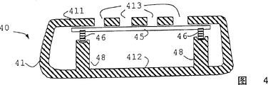
Fig. 4 represents a kind of loud speaker, and diaphragm wherein is the printed circuit board (PCB) (PCB) of mobile phone inside.
Fig. 5 represents some other the position of gm global tech operations inc [us];
Fig. 6 is the sectional view by a loud speaker, and diaphragm wherein links;
The work of the loud speaker of Fig. 7 presentation graphs 6;
Fig. 8 A represents the mobile device that loud speaker is wherein linked;
Fig. 8 B represents the sectional view of Figure 1A that A-A along the line gets;
Fig. 9 A is the perspective view of an example of sounding component with hinge joint of the hinged part that comprises piezoelectric;
Fig. 9 B is the sectional view of the device of Fig. 9 A;
Figure 10 A is the perspective view according to second example of the present invention;
Figure 10 B is the sectional view of the device of Figure 10 A;
Figure 11 is the root-mean-square value frequency response curve of the example of Figure 10;
Figure 12 A is the perspective view according to another device of the present invention;
Figure 12 B is the end view of the device of Figure 12 A;
Figure 13 A is mounted in the perspective view of example of the sound generating device of the hinge joint on the framework movably;
The critical elements of the further presentation graphs 13A of Figure 13 B;
Figure 14 is the perspective view of mobile phone with boombox of the diaphragm that comprises hinge joint; And
Figure 15 is the perspective view of woofer with diaphragm of hinge joint.
Embodiment
In first aspect, the invention provides a kind of for example loud speaker of mobile phone of portable electronic device that is used for, it comprises supporting construction, electricity is installed thereon activates actuator, described actuator partly links to each other with large tracts of land of housing of described device again, and the part of described housing is as the sound generating element of loud speaker.
Loud speaker of the present invention has several advantages.At first, the sound generating element of loud speaker (for example diaphragm) can be a big part of required housing, provides big area to be used to launch sound.This makes it possible to produce high sound pressure level (SPL) under low frequency.The second, the area of sound generating element is more much bigger than the area of ear canal aperture,, makes when making loud speaker remain close to ear the ear that energy density can high induced damage resistive hearer promptly greater than about 1 centimetre width.The 3rd, because the sound generating element is the part of housing, do not need the speaker diaphragm that provides independent, thereby reduce the quantity of the part of device.
All portable electron devices all comprise certain housing.Housing generally is an injection molding, forms a thin and light solid lid that is used for described device.In loud speaker of the present invention, the remainder of large tracts of land of housing part and housing separately, as cutting away, so that be used as the sound generating element of loud speaker from housing.This element can have any suitable shape.For example can be circular, rectangle or difform, but preferably the profile of the housing of its shape and device be consistent.The sound generating element can form a continuous surface, perhaps can comprise hole or interval, and other element of device for example display, keyboard, camera etc. stretches out by described hole or interval.The sound generating element can be flat, but preferably crooked or domeshape, so that improve its rigidity.The sound generating element can be made by cutting by molded housing really, but its element of cooperating with the suitable opening of housing of the shape made separately of quilt preferably.Under latter event, the material of element and design can be optimised, for example according to quality and rigidity, so that work as the sound generating element.
Gap between the remainder of the edge of sound generating element and housing can be by means of the element sealing of submissive encapsulant or suspension, as the loud speaker of routine.This potted component is used to prevent the sound that the sound interference sent is backward sent forward, and stops entering of dirt.But, in a preferred embodiment of the invention, do not provide this sealing.This gap is designed to fully little, and is less than 2mm, better less than 0.5mm.Have this little gap, sound interference can be ignored, and the dirt that enters is minimum.A kind of loud speaker that does not have to seal is novel, itself is an invention.
In a second aspect of the present invention, a kind of loud speaker is provided, comprise fixed part, actuator and sound producing component, wherein the gap between described sound generating element and described fixed part does not seal or hanging element in the gap fully less than 2mm.
In the preferred embodiment of a second aspect of the present invention, provide vertical (perhaps subvertical) antelabium along the edge that also centers on the sound generating element, described antelabium inwardly stretches into device from the edge of sound generating element.The length of antelabium and the same order of magnitude of maximum displacement of element during operation perhaps greater than described maximum displacement, make it as the sound baffle, and enough acoustic resistances are provided, and so as to further minimizing from the interference of emission sound rearward.In another embodiment, provide corresponding adjacent antelabium, be used to the acoustic resistance that provides bigger round the encirclement edge of fixed part.
Sound generating element according to first aspect present invention is the part of housing, and promptly it is on the outer surface of device.As another kind of scheme, any large tracts of land element in device can be as the sound generating element of loud speaker.For example, in mobile phone, inner large tracts of land element comprises printed circuit board (PCB), battery, battery container and keyboard.In these any one can link to each other with the actuator that electricity activates, thereby loud speaker is provided.Its advantage is, do not need the speaker diaphragm that provides independent, thereby saves the space.For sound can externally be heard, in housing, provide suitable port or hole, as the loud speaker of the mobile phone of routine.This itself is novelty thereby creative as the sound generating element to use existing inner member.
Therefore, in a third aspect of the present invention, provide a kind of loud speaker that is used for portable electronic device, wherein portable electron device sound generating element that inner large area functional element is a loud speaker.
The sound generating element of loud speaker links to each other with the actuator that electricity activates.The material that electricity activates is a response electric field and change the material (perhaps opposite, as when when mechanically actuated, to produce electric field) of shape.The electricity active material comprises piezoelectric, and it expands by electric field excitation the time or shrinks, and electrostriction material, and it shrinks in electric field.Example wherein has for example PZT (plumbous zirconates, titanate), piezopolymer PVDF (poly-inclined to one side two hexene fluorides) and electrostrictive ceramic PMNT for example for example of piezoelectric ceramic.Basic electric activation effect is very little, and for the block electric active material of cm size, when being activated by electricity, generally its displacement is not more than the part micron.Thereby the actuator of loud speaker of the present invention is not simple block electric active material, but can produce a kind of structure that electricity activates and electrode material constitutes of at least 10 microns motion.
This electricity activates actuator can have known structure, for example piezoelectric actuator stack or one or several bool.But, preferably actuator is claimed " HELIMORPH " (TM) type of actuator, for example described in disclosed International Patent Application WO-01/47041 (PCT/GB00/04949) and WO-01/47318 (PCT/GB00/04953), or the recurvate bool type that piles up, be used for the sort of of loud speaker described in our unsettled UK Patent Application 0114655.4, this patent document is included in this as a reference.This actuator provides 100 microns or more displacement from the midget plant of a size (at least one dimension has only several millimeters usually) with 20mm or littler order of magnitude.Also can use other actuator, described as following sound generating element with reference to the hinge connection.
The end that electricity activates actuator links to each other with the sound producing component, and the other end is fixed, and makes when being encouraged by the signal of telecommunication displacement toward each other of the two ends of actuator.Because the sound generating element more freely moves than fixed part, make the sound generating element preferentially move so activate.Specifically, the actuating that audio signal causes causes the vibration of sound generating element, thereby produces sound.
Actuator can be positioned at the position at about center of sound generating element, in the loud speaker as routine.In the loud speaker of routine, actuator is a voice coil type electromagnetic actuators normally.This actuator is very responsive for the motion of leaving axis, because the gap in the magnet that electric coil seesaws along its work must be very little, so that keep enough magnetic field intensitys.But, electricity of the present invention activates actuator and is not restricted to accurately motion vertically, and this makes it possible to actuator is arranged to eccentric.This is favourable when loud speaker is used in the device of limited space system, and the like portable electron device for example situation of mobile phone, portable computer and PDA is such, because actuator can be positioned at any position easily, and not only is positioned at the center.Though eccentric actuator is known for sound generating element wherein with the loud speaker (being also referred to as " distributed " loud speaker) of surface wave mode work, but it is novel using eccentric actuator at the sound generating element in the loud speaker of piston mode work, this itself just creative.
Therefore, in a fourth aspect of the present invention, provide a kind of loud speaker with the work of piston mode, wherein actuator is not positioned at the center with respect to the sound generating element.
As mentioned above, the loud speaker according to a first aspect of the present invention comprises an actuator.Though this forms a preferred embodiment of the present invention, another optional embodiment but comprises two or more actuators.When load can distribute between actuator, this was favourable, this thereby make that the power of each actuator needn't be too big.In addition, the big relatively area of sound generating element is driven in more than one position, and this allows it to have less rigidity, perhaps can be made by the rigidity materials with smaller, thereby have lighter weight.In addition, use more than one actuator can improve balance and stability.Several actuators, two actuators for example can make each be positioned at or towards an end of sound generating element, perhaps 4 actuators, each is positioned on the angle of rectangle sound generating element, perhaps can use any amount of loud speaker that is set at any position.Use several actuators to drive the sound generating element with the work of piston mode, this itself is novel in creative.
Thereby, in a fifth aspect of the present invention, providing a kind of loud speaker, one of them sound generating element is driven by several actuators.
When being used for above-mentioned electronic installation according to the loud speaker of a fifth aspect of the present invention is favourable.But, also be favourable as the loud speaker in other application.For example, among the embodiment in this aspect of the invention, provide a kind of woofer, be commonly referred to as woofer, super woofer or inferior woofer comprise the large-area panel that is driven by a plurality of actuators.Preferably panel has the size that rice is taken advantage of meter order of magnitude, and actuator is that the electricity of HELIMORPH type activates actuator, and is arranged on the rear of panel.One end of actuator and the rear of panel link to each other, and the other end links to each other with the fixed part that can not move.The actuator that provides is many more, then provides the power of each required actuator of high sound pressure level more little.Thereby, preferably have the actuator more than 4, can have the actuator more than 10 or 10.
In another embodiment of the present invention, be rotationally connected by sweep or link or install (being commonly referred to as hinge joint later on) sound generating element at one or several point, and at the described sound generating element of one or several some actuating.This moment, the motion of sound generating element not exclusively was in the form of piston, that is, when operation, be not the sound generating element lip-deep all points all mobile phase with distance.The advantage of articulated structure is that actuator can be set up and be installed in the outside in the zone under the sound generating element, because do not need the driving of balance.In addition, hinge provides non axial stability, and does not have unwanted rigidity or resistance along driving direction.
The simple embodiment of the sound generating element of hinge joint is the sound generating element that at one end activated by hinge joint and at the other end.According to a first aspect of the present invention, the sound generating element is a large tracts of land part of housing.In the present embodiment, a simple hinge, for example pearl or the sweep made of elastomeric material links to each other an end of housing and sound producing component.At the other end of sound generating element, electricity activates actuator and links to each other with the sound producing component at the one end, links to each other with a fixed part at its other end, and described fixed part is the inner surface of housing preferably.When work, actuator moves an end of coupled sound generating element, and the other end near hinge of sound generating element does not move substantially fully.Described motion quite is similar to the motion of hand-held fan, and inswept volume is the cylindrical section of certain angle.This motion comprises around the rotation key element of the axis that is parallel to the sound generating element.In another embodiment, provide separated two or more hinge along the straight line at the edge of sound generating element, thereby improved stability is provided.Really, wherein the design of the loud speaker that linked of sound generating element itself is novel in creative.
Therefore, in a sixth aspect of the present invention, provide a kind of loud speaker, wherein the sound generating element is used for sonorific motion and comprises the rotation that centers on the axis that is parallel to diaphragm.
In a preferred embodiment of a sixth aspect of the present invention, supporting diaphragm at one or several point by hinge, pivot or bool.
In another embodiment of the present invention, described hinge is included in and makes as a whole hinge in the sound generating element.For example, when the sound generating element is the plastic plate of given thickness, can provide one or several thin zone as hinge.In when assembling, the sound generating element is fixed on an end of hinge, make that the material on the opposite side at hinge is as the sound generating element when work.This sound generating element is made easily, for example by means of injection molding.
Another preferred embodiment of a sixth aspect of the present invention relates to a kind of for example loud speaker of mobile phone of portable electron device that is used for, wherein Jiao Jie sound generating element is transparent, and cover screen, perhaps cover some areas of screen and the housing around it.The advantage of this structure is to provide large-area sound generating element, thereby produces high sound pressure level and do not hinder screen under low frequency.In this case, the sound generating element of hinge joint is especially favourable, because actuator is positioned at the periphery of sound generating element, not in the center at screen place.
In another preferred embodiment of a sixth aspect of the present invention, the sound generating element of the loud speaker of hinge joint is provided at for example inside of computer, mobile phone, portable computer or PDA of electronic installation.The sound generating element be large-area and can be positioned at device housing under, the area top that described housing is included in the sound generating element is used to provide the port of sound.
Perhaps, the sound generating element of described hinge joint can also deeper be positioned at the inside of device, has the port at specific direction guiding sound in the selection zone of housing.
The sound generating element that in this device, can have in addition, more than one hinge joint.For example, can have two sound generating elements, respectively have one at each end that installs, they are separated by baffle, and have port at corresponding each end of device in housing, are used to produce two independent sound.It can produce stereo like this.Can also use the transfer function (HRTF) relevant in the electronics mode to input signal, thereby produce psychoacoustic surround sound with head.This may be particularly advantageous, for example is used for watching film on portable computer and PDA.
Advantageously, by actuator is arranged on hinge part near, perhaps by means of replacing the hinge part, making far-end at the sound generating element produce big displacement only needs a little actuator displacement.Thereby, can reduce the size of actuator along with the displacement that reduces, thereby can obtain than existing device small construction.
About this embodiment of a sixth aspect of the present invention, actuator preferably is made into cylindrical, wherein removes a part of extending along the longitudinal axis of cylinder.This actuator has the cross section of C shape, and the one end is installed on the supporting construction, and the other end is applying power on the edge near the sound generating element of hinge.
In the foregoing description of the sound generating element that links, actuator is placed near near the sound generating element, perhaps the far-end of close sound generating element.But, can between the part of extending of sound generating element and actuator or actuator, select contact point arbitrarily, come to transmit power thereby transmit motion to its other part from contact point as long as this sound generating element has enough rigidity along the length and the width of sound generating element as lever.
In a seventh aspect of the present invention, the above-mentioned device that comprises sound generating element, hinge part and electricity activation actuator is installed on the frame element.Described frame element is fixed on the supporting construction again flexibly.As mentioned above, described supporting construction can be the part of the inside of the housing of portable unit or shell or portable unit.
According to this aspect of the present invention, can constitute oscillation device together by flexible framework and the speaker unit of installing.This obtains a kind of system effectively, and this system can be considered to have the vibration or the oscillatory system of two degrees of freedom.This system can be modeled into have two fundamental resonance frequency by two quality and two systems that spring constitutes.In this example, the sound generating element is a quality, and actuator constitutes relevant spring together with acoustic impedance.The combination quality of sound generating element, actuator and framework is the quality of second oscillator.Second spring is can the flexible framework of installing.
The resonance frequency of this element or each frequency can be with the whole bag of tricks adjustment well known to those skilled in the art.For example, can change resonance frequency by the rigidity that changes the element that flexibly connects between provide the structural support and the framework.Perhaps, can adjust resonance frequency with the combination quality that is installed in the speaker system on the framework by changing framework.Thereby by selecting below the 200Hz, preferably below the 150Hz, even be more preferably the resonance frequency of the framework that the following flexibility of 100Hz installs, and can be by the flexible framework of installing of external drive excitation, make vibration or vibration in the frequency range that does not produce big sound output from speaker system.Though on principle, can provide excitation or actuating force by another actuator that is installed between supporting construction and the framework, in a preferred embodiment, this power activates actuator by the electricity that drives the sound generating element and produces.Thereby system is preferably designed like this, makes framework not produce big motion in the frequency range of the big audio frequency output of loud speaker generation.
In this embodiment, resonance frequency is adjusted like this, makes that at audio frequency be more than the 200Hz, and the mechanical impedance of system, rigidity or inertia are enough big, so that stop the motion of framework with respect to supporting construction.
In Figure 1A, show a kind of mobile phone handsets 10.Mobile phone 10 comprises known features such as housing 11, touch-sensitive keyboard area 12, screen 13 and antenna 14.Shown speaker system comprises the area expansion 15 of housing, and this part is as sound generating element or diaphragm, by piezo-activator 16 drivings thereunder.
Figure 1B is the sectional view of the mobile phone 10 of Figure 1A of getting along line AB.Show sound generating element 15 at the top of figure, it is adjacent with housing 11, has a little gap 17 betwixt.Actuator 16 at one end is connected the below of diaphragm 15, is connected on the supporting construction 18 at its other end, and described supporting construction is installed in the housing 11 of mobile phone 10.Actuator 16 is used to provide the circuit (not shown) of the electric oscillation under the audio frequency to link to each other with one.The electric field that produces between the electrode of HELIMORPH actuator 16 makes it expand or contraction along the direction shown in the double-headed arrow 19, makes diaphragm 15 vibrate under audio frequency, thereby produces sound.
Fig. 2 shows another embodiment of the loud speaker of the present invention in mobile phone 20.In this example, sound generating element 25 (being decorated with shade) has the hole of rectangle roughly ringwise, and screen 23 stretches out by described hole.Sound generating element and housing 21 flush, and are driven by a pair of stacked recurvate sweep piezo-activator 26, and described actuator is positioned at the below of diaphragm 25, on each side of screen 23.
Figure 3 illustrates the cutaway view by one embodiment of the present of invention, wherein the adjacent edge of the edge of diaphragm 35 and housing 31 comprises antelabium 39, as additional acoustic resistance.Diaphragm 35 is placed in the hole of housing 31, has a little gap 37 therebetween.As previously mentioned, the HELIMORPH actuator that at one end linked to each other with framework 38 of diaphragm 35 36 drives.Vertical antelabium 39 extends on every side at the outward flange of diaphragm 35 and the adjacent edge of housing 31, makes when diaphragm 35 moves up and down when working, and the gap 37 between housing 31 and diaphragm 35 keeps very little.Described antelabium is used to help to stop sound to radiate backward from the downside 351 of diaphragm 35, in order to avoid disturb the sound that radiates forward from the upside 352 of diaphragm 35.Even when the antelabium on the housing 31 39 had short length (perhaps not having), the antelabium 39 on diaphragm 35 also kept a narrow gap 37, thereby keeps a high acoustic resistance.
In Fig. 4, printed circuit board (PCB) (PCB) 45 is as the diaphragm of loud speaker.Printed circuit board (PCB) 45 is internal functional elements of mobile phone 40, and Fig. 4 is its sectional view.Two stacked linking to each other with actuator 46 on the framework 48 on described circuit board and the downside that is positioned at housing 41 to the rear bending part.Actuator 46 expands when being subjected to electric excitation and shrinks, and PCB is moved up and down, thereby produces sound.With sound producing component 45 adjacent areas in, provide a plurality of ports 413 on the side of housing 41, so that sound can be overflowed.Opposite side 412 at housing does not provide port, thereby the sound of radiation is backward reduced to minimum.
In Fig. 5 with from the form of plane graph show several possible layout of actuator 56 loud speaker of the present invention.Be depicted as HELIMORPH actuator 56, but also can use other piezo-activator.In Fig. 5 A, speaker diaphragm 55 and housing 51 be a little gap 57 (being decorated with shade) separately.HELIMORPH actuator 56 is positioned at the below of diaphragm 55, is in an eccentric position.When having other element below the dead point of diaphragm 55, this may be favourable.In Fig. 5 B, show another embodiment, wherein diaphragm 55 is set at two HELIMORPH actuators, 56 drivings of each end.Fig. 5 C shows another embodiment, comprising 4 HELIMORPH actuators 56, respectively has one on each turning of diaphragm 55.In Fig. 5 D, speaker unit of the present invention has ring film 55.Described diaphragm 55 at one end is in the same place with a bullet 59 hinge joints of silicon rubber, and is driven by HELIMORPH actuator 56 at the other end.Actuator 56 is in the below of housing 51 and diaphragm 55, and at one end 561 link to each other with the inside of housing 51, link to each other at the downside of the other end 562 with diaphragm 55.
Fig. 6 further shows the work of diaphragm device of the hinge joint of Fig. 5 D.Diaphragm 65 is linked at hinge 69 places, and described hinge is installed on the housing 61, and is a bit occupying gap 67 between diaphragm 65 and the housing 61 on the circumference of diaphragm 65.Relative on the periphery of diaphragm 65 some diaphragm 65 is driven by HELIMORPH actuator 66, and described actuator links to each other with diaphragm 65 at one end 661, links to each other with housing 61 at its other end 662.This is a kind of compact especially loud speaker, and this is that its thickness generally is not more than 2 millimeters because HELIMORPH device 66 is extremely thin, and slightly protrudes the inside that enters mobile device.
At Fig. 7 A, among B and the C, the motion when schematically showing diaphragm 75 and being energized.Fig. 7 A, B illustrates housing 71, hinge 79, diaphragm 75, actuator 76 and is connected 761,762 with C, as shown in Figure 6.In Fig. 7 A, actuator 76 is in its position that does not activated, thereby diaphragm 75 and housing 71 flush.In Fig. 7 B, actuator 76 is in the position of its extension, and diaphragm 75 is raised at that end, rotates around hinge 79.The position that does not activated of diaphragm 75 is by shown in the dotted line.In Fig. 7 C, actuator 76 is in its retracted position, and that end of diaphragm 75 reduces with respect to housing 71.As before, the position that does not activated of diaphragm 75 is shown in dotted line.Position at Fig. 7 B and Fig. 7 C, as can be seen, diaphragm has moved through angle [alpha] 1 and α 2 (for clarity sake by exaggerative greatly) with respect to its position that does not activated, thereby forms around the rotation of the axis that passes through hinge 79 extensions that passes paper, and described parallel axes is in the plane of diaphragm 75.
Fig. 8 A and Fig. 8 B represent to be included in the loud speaker of the Fig. 5-7 in the mobile phone 80, and Fig. 8 B is the sectional view of Fig. 8 A A-A ' along the line.Diaphragm 85 (being decorated with shade) is transparent, and is positioned at the top of screen 83.Shown in the figure for to be linked at two points 89.It is driven by HELIMORPH actuator 86, and described actuator at one end 861 is fixed on the housing 81, is fixed on the diaphragm 85 at the other end 862.The area approximation of diaphragm 85 equals 40 millimeters * 50 millimeters.Two hinges 89 are that silicon rubber is made, and are separated 18 millimeters.HELIMORPH actuator 86 is PZT actuators of a kind of multilayer, become by helical buckling an about annulus arc length 3/4.The PZT of multilayer has a kind of bimorph sweep structure, has two-layer PZT, and every layer thickness is 0.3 millimeter, has conventional electrode (not shown) between two-layer on the outer surface and described.The width of band is 2 millimeters, and screw diameter is 5 millimeters.Spiral is bent to the arc of the annulus of one 18 mm dia.Therefore, this loud speaker only occupies 18 millimeters of the diameters and the thick 5 millimeters space of mobile phone inside.The quality of actuator 86 is approximately 2.5 grams, and the quality of diaphragm 85 approximately is 0.3 gram.Under maximum excitation, the displacement of antelabium approximately is+/-200 microns.When audio signal was imported into actuator 86, the distance at 30 centimetres in the frequency range more than 100 hertz-10 KHz reached about 70 decibels sound pressure level (SPL).
As mentioned above, select HELIMORPH actuator 86 as basic electroactive effect, this actuator is very little, and for the electroactive material of centimetre size, when being electrically excited, its displacement generally is not more than 1 micron part.But, have been found that within the scope of the invention that the active actuators of other type also can successfully be used.
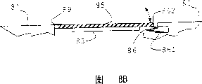
For this reason, be modified according to the hinge fraction of following example of the present invention, so that comprise electric active material.Referring to Fig. 9 A, wherein show with Fig. 8 category-A like the basic perspective view of hinge fraction.The figure shows a part and the diaphragm 95 of near the housing 91 hinge fraction.In this example, hinge fraction 99 comprises the tube element 96 that electroactive material is made.A part that is parallel to 90 degree of its main shaft of tube element 96 is removed, thereby forms the element 96 with approximate C tee section.Element 96 is as actuator.Housing 91 is fixed on first edge 961 of tube element 96, and sound generating element or diaphragm 95 are fixed on second edge 962 of tube element 96.
The length of electroactive tube element 96 is 25 millimeters, and external diameter is 4.4 millimeters, and tape thickness is 0.4 millimeter.When being energized, the angular movement that it can produce ± 0.33 degree around its main shaft has the 3.2 prevention torques of Newton meters in the least.This convert to diaphragm 95 the distally tache motorice 951 ± 0.26 millimeter displacement, shown in Fig. 9 B.Power in the equivalence at this edge approximately is 0.071N.The speaker system that this and above-mentioned HELIMORPH drive is suitable, and it has ± 0.2 millimeter displacement and the prevention power of 0.068N.Be applicable to that electricity of the present invention activates tube element 96 and described in patent document WO-02/17408 with other example of the rot of electricity activation, this document is included in this as a reference.
The quality of actuator 96 is 0.75 grams, and the quality of diaphragm 95 is 0.2 grams.But, because actuator 96 is positioned near the hinge, the inertia of actuator 96 is 1.5gmm
2, and the inertia of diaphragm 95 is 166gmm
2Therefore, though the speaker system that the mechanical performance of actuator 96 and above-mentioned HELIMORPH drive is similar, its inertia is negligible.Thereby actuator 96 drives the quality of himself without its a large amount of power.It is used to driven diaphragm 95.The basic resonance frequency of the loud speaker that hinge shown in Figure 9 drives approximately is 280Hz, thereby can produce the sound that can listen.
In another kind of structure, shown in Figure 10 A and 10B, frame structure 101 is supporting diaphragm or sound generating element 105.Diaphragm 105 has far-end 1051 and near-end 1052.At near-end, diaphragm 105 is fixed on the supporting construction 101 by means of hinge fraction 109, and this makes that diaphragm 105 can be around the rotational of hinge fraction.
Actuator 106 is a kind of C shape actuators as using in the top example, and it is installed in the back side of supporting construction 101, and extends to the near-end of diaphragm 105 by a groove in this structure.It is applicable to it advocate and will apply along the direction on the plane of diaphragm 105, so as to making the rotational of diaphragm 105 around hinge 109.The part of diaphragm 105 and provide a little additional lever from any parts 1053 that diaphragm stretches out is so that further improve from the power transmission of actuator 106 to diaphragm 105.
Diaphragm 105 is made by Merlon, is hot pressed into the shape of fold, so that increase its rigidity, keeps low weight simultaneously.Other material with low weight and high rigidity for example fibre reinforced plastics is equally applicable to the use relevant with the present invention.Diaphragm 105 can have more complex inner structure, for example comprises the stiffener that is sandwiched in the honeycomb shape between two-layer lightweight material or its analog.
Diaphragm 105 has the edge part 1054 of big flexibility, below seal membrane 105 or the half space of back.In present example, described seal is formed by the antelabium of thin Merlon, and a thereby integral part of formation diaphragm 105.
Figure 11 shows the frequency response of speaker unit.Having provided sound pressure level SLP with decibel among the figure, is to measure with the position of 1 millimeter of diaphragm 105 distance, and frequency range is 100Hz-20kHz (using logarithmic scale).
Figure 12 A, 12B show and can be used for producing the sound that can listen and an embodiment of vibration.Show the schematic diagram of the part of portable phone once more, it has housing 121 and comprises the sound generating element or the electricity of diaphragm 125 and above-mentioned HELIMORPH type activates the speaker system of actuator 126.But, the shown device and the difference of aforesaid device are that hinge fraction 129 is not installed on the housing or shell 121 of mobile device, and is installed on the frame structure 128.Frame structure 128 is fixed flexibly by means of flexible member 1281 again.In an example shown, flexible member is a steel spring.At its far-end, frame structure is by means of being fixed on the housing 121 with above-mentioned similar hinge fraction 1282.
The whole frame structure that comprises spring and hinge constitutes the oscillatory system with one degree of freedom ideally.Described system is energized and resonance by means of drive actuator 126, and its resonance frequency is determined by the rigidity and the quality of spring 1281.Described resonance is regulated like this, makes under audio frequency (being more than the 200Hz) that the impedance of system is enough big, so that stop the motion with respect to the panel of matrix.
First spring 1281 is to be made into by the spring steel around crooked 25 microns of the metal wire former of 1 mm dia.The resonance frequency of this device obtains by utilizing laser displacement gauge (LDM) to measure its free vibration (responding manual displacement).The frequency of measuring is 60 hertz.By the power/placement property of measuring spring, the rigidity of trying to achieve spring is 216Nm
-1The size of original spring is as follows:
Length=5 millimeter
Width=4 millimeter
Highly=3 millimeter
About angle=31 degree
The rigidity of resonance frequency of known system (60Hz) and spring, can obtain apparent mass:
[1]
The actual mass of system is as follows:
Quality=the 0.552g of actuator 126
Quality=the 1.541g of framework/diaphragm 125
Gross mass=2.093g
Apparent mass=1.520g
Mass ratio=0.726
Quality than the mass centre of indication device be positioned at distance connect actuator 126 a terminal membrane sheet 125 length 1/4 near.
For the frequency range of adjusting device, the response of the oscillator element that takes off by mobile phone available on the market of having used LDM and accelerometer measures.Described device is made of a little motor with rotor of uneven weight, and described motor produces power when rotated.To different voltage measurements response, the range of target frequencies of auto levelizer is 75-80Hz, thereby a little more than the resonance frequency of primitive apparatus.
Size and feature by with reference to original spring are estimated as the required size of resonance that reaches about 80Hz:
Length=6mm
Width=8mm
Highly=3mm.
Made spring and be assembled in the device according to these approx. dimensions.The resonance frequency of measuring is 89Hz, a little more than target zone.Thereby, be a scope position (seeing Figure 12 B) that the 0.1 little quality 1283 that restrains-0.2 gram is additional to the close actuator 126 of framework.
The change of the resonance frequency of gained is in the target zone device.Quantitative comparison shows that of the amplitude of the vibration that is reached by the device of primary oscillator and combination, primitive apparatus produces bigger vibration, though the device of combination is in the same order of magnitude.
By means of composite set is linked to each other with a base plate that is presented on the resonance manner under the tuned frequency, can further improve the performance of composite set.
Figure 13 shows the plane graph (Figure 13 A) and the sectional view (Figure 13 B) of the signal of the speaker diaphragm 135 with integral hinge.Diaphragm 135 has as two of hinge narrow zones 139.Show two fixing points 1391 on a side of hinge, have the sound generating zone 135 on the opposite side of hinge.HELIMORPH actuator 136 drives sound generating element 135 at its end farthest apart from hinge 139.Figure 13 B shows an additional steady pin 1392, and it is provided with by fixing point 1391.Steady pin 1392 and actuator 136 all are installed in the inside of housing 131.Hole in housing 131 is provided at its inside to the sound passage between the outside.
Figure 14 shows the mobile phone 140 of the boombox with the diaphragm 145 that comprises hinge joint.For illustrative purposes, its front is not shown.Two loud speakers are that similarly each loud speaker is positioned at per half mobile phone 140.Each loud speaker comprises diaphragm 145 and HELIMORPH actuator 146.Each diaphragm 145 comprises as two of hinge thin 149, two fixing points 1491 in zone and sound producing components 145.When actuator 146 was energized, the sound generating element is " beating " about in the of 145, thereby produced sound.Every end 1411 and 1412 at device provides port one 413, makes sound to give off, shown in hollow arrow.Half of length along device provides baffle 147, is used to provide the isolates sound of two compartments at loud speaker place.When stereosonic two passages during by 146 inputs of each actuator, then produce the sound of two sound channels, each is emitted since every end 1411,1412 of device.Device shown in Figure 14 is a kind of mobile phone, but also can be the screen compartment of PDA, portable computer or these devices.
Shown in Figure 15 is to have the woofer that a plurality of electricity activate actuator.Loud speaker 150 comprises framework 151 (being decorated with shade), and 20 HELIMORPH actuators 156 (dotting) are installed on it, and the other end of described actuator (free end) links to each other with lightweight panel 155 as the sound generating element.As common loud speaker, provide the housing (not shown) at the rear of sound generating element, be used to absorb the sound that rearward sends.Perhaps can an acoustic absorption device (not shown) be installed, be used to absorb the sound that send at the rear at the rear of panel.The height of panel 155 is 44cm, and width is 77cm.Each actuator 156 is the shape of the helical buckling part that is curved annular, and the diameter of spiral is 5mm, and the diameter of annulus is 50m.Panel is a large tracts of land panel of being made by lightweight material, and the polymer foams of covering is for example arranged, and its thickness is several millimeters, and quality is approximately 200 grams or littler.When being encouraged simultaneously, actuator makes the mode back and forth movement of panel with piston, and maximum displacement is ± 2mm.Under 20 hertz low frequency,, be 100dB by the available sound pressure level of this loud speaker in the distance of distance panel 1mm.Thereby shown in loud speaker form a powerful woofer, compare with conventional moving-coil woofer, its volume is very little, and in light weight.
In addition, at the application number of June 21 calendar year 2001 application is that UK Patent Application that 0115244.6 name is called " LOUDSPEAKER " has been described and can be implemented multiple apparatus and method of the present invention, the application requires its priority, and this patent document is included in this as a reference.
Claims (19)
1. loud speaker that is used to produce the sound that to listen, comprise the sound generating element that is installed on the supporting construction, and be connected at least one actuator between described supporting construction and the described sound generating element, described at least one actuator is used to make described sound generating element motion to produce sound, and the motion of described sound generating element comprises rotation.
2. loud speaker as claimed in claim 1, wherein said sound generating element is supported by hinge, pivot or bool one or more.
3. loud speaker as claimed in claim 2, wherein said sound generating element links together with described supporting construction near side (ns) edge, thereby forms described hinge, pivot or bool, separates with described supporting construction at other edge simultaneously.
4. loud speaker as claimed in claim 3, wherein in the edge of described sound generating element and the gap between the described supporting construction by one or several submissive potted component bridge joint.
5. loud speaker as claimed in claim 1, wherein said actuator is a ceramic actuator.
6. loud speaker as claimed in claim 1, wherein said actuator is made by piezoelectric.
7. loud speaker as claimed in claim 6, wherein said actuator is used for rotating when being energized.
8. loud speaker as claimed in claim 7, wherein said actuator constitutes at least a portion of described hinge, pivot or bool.
9. loud speaker as claimed in claim 7, wherein said actuator in a tubular form, a part wherein is removed.
10. loud speaker as claimed in claim 6, wherein said actuator is used for extending point-blank when being energized.
11. loud speaker as claimed in claim 10, wherein said actuator is the shape of the coil of twice winding.
12. loud speaker as claimed in claim 1, wherein said sound generating element is installed on the framework, and described framework is installed on the described supporting construction flexibly.
13. loud speaker as claimed in claim 1, wherein said rotation are around the axis that is parallel to the sound generating element.
14. loud speaker as claimed in claim 1, wherein said sound generating element by with the integrally formed hinge support of this sound generating element.
15. loud speaker as claimed in claim 14, wherein said sound generating element is the plastic sheet with given thickness, and described hinge is the other part with described plastic sheet littler than the thickness of sound generating element.
16. loud speaker as claimed in claim 1, wherein said sound generating element is transparent.
17. energy reproduction of stereo sound mancarried device that comprises two described loud speakers of claim 1.
18. mancarried device as claimed in claim 17, wherein two loud speakers are arranged in the compartment that separates by baffle in this device, and described compartment has the port that is positioned at this device opposite end and sends to allow sound.
19. energy reproduction of stereo sound television system that comprises two described loud speakers of claim 1.
Applications Claiming Priority (6)
| Application Number | Priority Date | Filing Date | Title |
|---|---|---|---|
| GB0115244.6 | 2001-06-21 | ||
| GB0115244A GB0115244D0 (en) | 2001-06-21 | 2001-06-21 | Loudspeaker |
| GB0122800.6 | 2001-09-21 | ||
| GB0122800A GB0122800D0 (en) | 2001-09-21 | 2001-09-21 | Loudspeaker for portable electronic devices |
| GB0205750.3 | 2002-03-12 | ||
| GB0205750A GB0205750D0 (en) | 2002-03-12 | 2002-03-12 | Loudspeaker |
Publications (2)
| Publication Number | Publication Date |
|---|---|
| CN1547869A CN1547869A (en) | 2004-11-17 |
| CN1305350C true CN1305350C (en) | 2007-03-14 |
Family
ID=27256199
Family Applications (1)
| Application Number | Title | Priority Date | Filing Date |
|---|---|---|---|
| CNB028165195A Expired - Fee Related CN1305350C (en) | 2001-06-21 | 2002-06-19 | Loudspeaker |
Country Status (7)
| Country | Link |
|---|---|
| US (1) | US7302068B2 (en) |
| EP (1) | EP1397937A2 (en) |
| JP (1) | JP3994086B2 (en) |
| KR (1) | KR20040014569A (en) |
| CN (1) | CN1305350C (en) |
| AU (1) | AU2002310642A1 (en) |
| WO (1) | WO2003001841A2 (en) |
Families Citing this family (48)
| Publication number | Priority date | Publication date | Assignee | Title |
|---|---|---|---|---|
| GB2386026B (en) * | 2002-02-28 | 2005-06-08 | 1 Ltd | Loudspeaker |
| GB0220750D0 (en) * | 2002-09-06 | 2002-10-16 | 1 Ltd | Rugged electroactive loudspeaker design |
| EP1634481B1 (en) * | 2003-05-28 | 2007-03-14 | Koninklijke Philips Electronics N.V. | Display screen loudspeaker |
| GB0324051D0 (en) * | 2003-10-14 | 2003-11-19 | 1 Ltd | Loudspeaker |
| WO2005053356A1 (en) * | 2003-11-17 | 2005-06-09 | 1... Limited | Loudspeaker |
| US7346315B2 (en) * | 2004-03-30 | 2008-03-18 | Motorola Inc | Handheld device loudspeaker system |
| WO2005104614A1 (en) * | 2004-04-22 | 2005-11-03 | 1...Limited | Loudspeaker |
| US20060103762A1 (en) * | 2004-11-18 | 2006-05-18 | Ly Ha M | Interactive imaging apparatus and method of operation thereof |
| CA2600015A1 (en) * | 2005-03-01 | 2006-09-08 | Todd Henry | Electromagnetic lever diaphragm audio transducer |
| US20080247595A1 (en) * | 2005-03-01 | 2008-10-09 | Todd Henry | Electromagnetic lever diaphragm audio transducer |
| EP1905002B1 (en) * | 2005-05-26 | 2013-05-22 | LG Electronics Inc. | Method and apparatus for decoding audio signal |
| JP4988716B2 (en) | 2005-05-26 | 2012-08-01 | エルジー エレクトロニクス インコーポレイティド | Audio signal decoding method and apparatus |
| JP2007150393A (en) * | 2005-11-24 | 2007-06-14 | Matsushita Electric Ind Co Ltd | Telephone device |
| EP1974345B1 (en) * | 2006-01-19 | 2014-01-01 | LG Electronics Inc. | Method and apparatus for processing a media signal |
| JP2009526264A (en) | 2006-02-07 | 2009-07-16 | エルジー エレクトロニクス インコーポレイティド | Encoding / decoding apparatus and method |
| US20070188053A1 (en) * | 2006-02-14 | 2007-08-16 | Robert Bosch Gmbh | Injection molded energy harvesting device |
| US7983432B2 (en) * | 2006-09-29 | 2011-07-19 | Shure Acquisition Holdings, Inc. | Point excitation placement in an audio transducer |
| US7414351B2 (en) * | 2006-10-02 | 2008-08-19 | Robert Bosch Gmbh | Energy harvesting device manufactured by print forming processes |
| US8000489B2 (en) * | 2006-10-30 | 2011-08-16 | Sony Ericsson Mobile Communications Ab | Speaker module for electronic device |
| US20080232636A1 (en) * | 2007-03-23 | 2008-09-25 | Sonic Dynamics, Llc | Sonic piston |
| US7848536B2 (en) * | 2007-11-02 | 2010-12-07 | Onkyo Corporation | Voice coil assembly, loudspeaker using the same, and method for producing the same |
| JP4420104B2 (en) * | 2007-11-02 | 2010-02-24 | オンキヨー株式会社 | Magnetic circuit module, magnetic circuit for speaker, manufacturing method thereof, and speaker using the same |
| US8301188B2 (en) * | 2008-11-06 | 2012-10-30 | Sony Ericsson Mobile Communications Ab | Electronic devices including substrate mounted acoustic actuators and related methods and mobile radiotelephones |
| US8260343B2 (en) * | 2008-11-06 | 2012-09-04 | Sony Ericsson Mobile Communications Ab | Electronic devices including vertically mounted loudspeakers and related assemblies and methods |
| US20100323641A1 (en) * | 2009-06-22 | 2010-12-23 | Qualcomm Incorporated | Method and apparatus for using pre-distortion and feedback to mitigate nonlinearity of circuits |
| KR101318490B1 (en) * | 2009-07-22 | 2013-10-16 | 닛본 덴끼 가부시끼가이샤 | Electronic device |
| KR101622632B1 (en) * | 2009-08-26 | 2016-05-20 | 엘지전자 주식회사 | Mobile terminal |
| US20110123060A1 (en) * | 2009-11-20 | 2011-05-26 | Cheng-Ho Tsai | Vibrator of an electro-acoustic transducer |
| TW201125372A (en) | 2010-01-15 | 2011-07-16 | Univ Nat Chiao Tung | Piezoelectric panel speaker and optimal design method of the same |
| TW201136331A (en) * | 2010-04-06 | 2011-10-16 | Zhao-Lang Wang | Moving-magnet type loudspeaker device |
| US8543168B2 (en) * | 2010-12-14 | 2013-09-24 | Motorola Mobility Llc | Portable electronic device |
| US9407984B2 (en) * | 2011-02-24 | 2016-08-02 | Htc Corporation | Method and apparatus for adjusting sound quality |
| JP6092526B2 (en) * | 2012-05-14 | 2017-03-08 | 京セラ株式会社 | Electronics |
| GB2508639A (en) * | 2012-12-06 | 2014-06-11 | Pss Belgium Nv | A loudspeaker diaphragm electro-actively driven at its edges |
| WO2015098090A1 (en) * | 2013-12-26 | 2015-07-02 | 京セラ株式会社 | Electronic instrument |
| US10129640B2 (en) | 2014-02-06 | 2018-11-13 | Hewlett-Packard Development Company, L.P. | Suppressing a modal frequency of a loudspeaker |
| PE20181440A1 (en) | 2015-09-14 | 2018-09-12 | Wing Acoustics Ltd | IMPROVEMENTS IN OR RELATED TO AUDIO TRANSDUCERS |
| DE102015217778B4 (en) * | 2015-09-17 | 2019-05-29 | Robert Bosch Gmbh | Acoustic sensor with a membrane and an electroacoustic transducer |
| US9820035B2 (en) * | 2016-03-25 | 2017-11-14 | Bose Corporation | Audio systems and apparatus for vibration isolation |
| GB2560878B (en) | 2017-02-24 | 2021-10-27 | Google Llc | A panel loudspeaker controller and a panel loudspeaker |
| US11166100B2 (en) | 2017-03-15 | 2021-11-02 | Wing Acoustics Limited | Bass optimization for audio systems and devices |
| WO2018172944A1 (en) | 2017-03-22 | 2018-09-27 | Wing Acoustics Limited | Systems methods and devices relating to hinges and audio transducers |
| CN111629841B (en) * | 2018-01-22 | 2022-04-29 | 华为技术有限公司 | Audio display screen with electroactive polymer bend member |
| EP3837859A4 (en) | 2018-08-14 | 2022-05-18 | Wing Acoustics Limited | Systems methods and devices relating to audio transducers |
| US10782731B1 (en) * | 2019-02-28 | 2020-09-22 | Google Llc | Modal frequency shifting for loudspeaker devices |
| GB201907267D0 (en) | 2019-05-23 | 2019-07-10 | Pss Belgium Nv | Loudspeaker |
| US11606633B2 (en) | 2019-12-10 | 2023-03-14 | Apple Inc. | Speaker assembly |
| NL2031944B1 (en) * | 2022-05-20 | 2023-11-27 | Microsoft Technology Licensing Llc | Tuning spring mass resonator of loudspeaker in mobile device |
Citations (2)
| Publication number | Priority date | Publication date | Assignee | Title |
|---|---|---|---|---|
| US6078126A (en) * | 1998-05-29 | 2000-06-20 | Motorola, Inc. | Resonant piezoelectric alerting device |
| CN1434985A (en) * | 1999-12-21 | 2003-08-06 | 1...有限公司 | Electro-active device |
Family Cites Families (13)
| Publication number | Priority date | Publication date | Assignee | Title |
|---|---|---|---|---|
| US1919632A (en) * | 1930-04-04 | 1933-07-25 | Rca Corp | Sound radiator |
| US3781955A (en) * | 1970-12-21 | 1974-01-01 | V Lavrinenko | Method of making a piezoelectric element |
| US3900748A (en) * | 1972-01-31 | 1975-08-19 | Zenith Radio Corp | Torsional ceramic transducer |
| JPS5475126A (en) | 1977-11-25 | 1979-06-15 | Hasegawa Chiyuukoushiyo Kk | Method of joining bar steel for deformed bar concrete |
| JPS54167701U (en) | 1978-05-17 | 1979-11-26 | ||
| DE3378456D1 (en) * | 1983-01-28 | 1988-12-15 | Intersonics Inc | Subwoofer speaker system |
| JPH0221896A (en) | 1988-07-11 | 1990-01-24 | Yamaha Motor Co Ltd | Single tank type washing machine |
| FR2649575A1 (en) | 1989-07-07 | 1991-01-11 | Thomson Consumer Electronics | Display screen with integrated electroacoustic function |
| US5514927A (en) * | 1994-02-28 | 1996-05-07 | Motorola, Inc. | Piezoelectric audio transducer |
| UA51671C2 (en) | 1995-09-02 | 2002-12-16 | Нью Транзд'Юсез Лімітед | Acoustic device |
| US5802189A (en) * | 1995-12-29 | 1998-09-01 | Samick Music Corporation | Subwoofer speaker system |
| PL345317A1 (en) | 1998-07-03 | 2001-12-03 | New Transducers Ltd | Resonant panel-form loudspeaker |
| GB9818719D0 (en) * | 1998-08-28 | 1998-10-21 | New Transducers Ltd | Vubration exciter |
-
2002
- 2002-06-19 US US10/480,733 patent/US7302068B2/en not_active Expired - Fee Related
- 2002-06-19 KR KR10-2003-7016680A patent/KR20040014569A/en not_active Application Discontinuation
- 2002-06-19 CN CNB028165195A patent/CN1305350C/en not_active Expired - Fee Related
- 2002-06-19 EP EP02735634A patent/EP1397937A2/en not_active Withdrawn
- 2002-06-19 WO PCT/GB2002/002836 patent/WO2003001841A2/en active Application Filing
- 2002-06-19 AU AU2002310642A patent/AU2002310642A1/en not_active Abandoned
- 2002-06-19 JP JP2003508097A patent/JP3994086B2/en not_active Expired - Fee Related
Patent Citations (2)
| Publication number | Priority date | Publication date | Assignee | Title |
|---|---|---|---|---|
| US6078126A (en) * | 1998-05-29 | 2000-06-20 | Motorola, Inc. | Resonant piezoelectric alerting device |
| CN1434985A (en) * | 1999-12-21 | 2003-08-06 | 1...有限公司 | Electro-active device |
Also Published As
| Publication number | Publication date |
|---|---|
| US20040202338A1 (en) | 2004-10-14 |
| EP1397937A2 (en) | 2004-03-17 |
| WO2003001841A3 (en) | 2003-09-12 |
| US7302068B2 (en) | 2007-11-27 |
| JP2004531173A (en) | 2004-10-07 |
| AU2002310642A1 (en) | 2003-01-08 |
| JP3994086B2 (en) | 2007-10-17 |
| WO2003001841A2 (en) | 2003-01-03 |
| KR20040014569A (en) | 2004-02-14 |
| CN1547869A (en) | 2004-11-17 |
Similar Documents
| Publication | Publication Date | Title |
|---|---|---|
| CN1305350C (en) | Loudspeaker | |
| EP1933539B1 (en) | Apparatus and method providing sound-produced tactile feedback | |
| JP5428861B2 (en) | Piezoelectric acoustic element and electronic device | |
| US7764804B2 (en) | Panel-typed loud speaker and an exciter therefor | |
| CN1581891A (en) | Sound reproduction device and portable terminal apparatus | |
| JP2009513051A (en) | Audio device improvements | |
| WO2007052835A1 (en) | Speaker, image element protective screen, case of terminal, and terminal | |
| CN1929700A (en) | Piezoelectric device for generating acoustic signals | |
| EP2597892A1 (en) | Vibration device | |
| TW200537962A (en) | Loudspeakers | |
| JPH11512262A (en) | Inertial vibration transducer | |
| CN109495832B (en) | Surface sound generating device and electronic equipment | |
| CN209787426U (en) | Vibration sound production device and electronic equipment | |
| JP2006129053A (en) | Flat-panel speaker | |
| JP3103081U (en) | Piston type panel type loudspeaker | |
| CN1875657B (en) | Sound generating transducer | |
| CN1228700C (en) | Electronic article comprising loudspeaker & touch pad | |
| US8824708B2 (en) | Oscillation device and electronic apparatus | |
| WO2014087961A1 (en) | Electroacoustic transducer, manufacturing method therefor, and electronic device utilizing electroacoustic transducer | |
| US11617039B2 (en) | Planar magnetic driver having trace-free radiant region | |
| GB2574591A (en) | Product with integrally formed vibrating panel loudspeaker | |
| CN1337140A (en) | Headphone | |
| JP2004135295A (en) | Loudspeaker unit and method for operating loudspeaker unit | |
| JP4688687B2 (en) | Piezoelectric vibration unit and panel speaker | |
| US10827243B1 (en) | Method and apparatus for fabricating an information handling system with a vibration actuator speaker system assembly |
Legal Events
| Date | Code | Title | Description |
|---|---|---|---|
| C06 | Publication | ||
| PB01 | Publication | ||
| C10 | Entry into substantive examination | ||
| SE01 | Entry into force of request for substantive examination | ||
| C14 | Grant of patent or utility model | ||
| GR01 | Patent grant | ||
| C17 | Cessation of patent right | ||
| CF01 | Termination of patent right due to non-payment of annual fee |
Granted publication date: 20070314 |