CN1299907C - Liquid jetting head and production method thereof - Google Patents
Liquid jetting head and production method thereof Download PDFInfo
- Publication number
- CN1299907C CN1299907C CNB2004100551797A CN200410055179A CN1299907C CN 1299907 C CN1299907 C CN 1299907C CN B2004100551797 A CNB2004100551797 A CN B2004100551797A CN 200410055179 A CN200410055179 A CN 200410055179A CN 1299907 C CN1299907 C CN 1299907C
- Authority
- CN
- China
- Prior art keywords
- area
- groove
- mould
- elongate grooves
- projection
- Prior art date
- Legal status (The legal status is an assumption and is not a legal conclusion. Google has not performed a legal analysis and makes no representation as to the accuracy of the status listed.)
- Expired - Fee Related
Links
- 239000007788 liquid Substances 0.000 title claims abstract description 41
- 238000004519 manufacturing process Methods 0.000 title claims description 28
- 239000004033 plastic Substances 0.000 claims description 50
- 238000000034 method Methods 0.000 claims description 31
- 239000000463 material Substances 0.000 claims description 29
- 239000002184 metal Substances 0.000 claims description 11
- 229910052751 metal Inorganic materials 0.000 claims description 11
- 230000010355 oscillation Effects 0.000 claims description 2
- 239000000976 ink Substances 0.000 description 92
- 238000004891 communication Methods 0.000 description 55
- 230000015572 biosynthetic process Effects 0.000 description 26
- PXHVJJICTQNCMI-UHFFFAOYSA-N Nickel Chemical compound [Ni] PXHVJJICTQNCMI-UHFFFAOYSA-N 0.000 description 24
- 239000012528 membrane Substances 0.000 description 24
- 238000005192 partition Methods 0.000 description 13
- 229910052759 nickel Inorganic materials 0.000 description 12
- 238000002347 injection Methods 0.000 description 11
- 239000007924 injection Substances 0.000 description 11
- 238000012545 processing Methods 0.000 description 11
- 230000008569 process Effects 0.000 description 10
- 239000007921 spray Substances 0.000 description 9
- 238000005260 corrosion Methods 0.000 description 7
- 230000007797 corrosion Effects 0.000 description 7
- 238000004080 punching Methods 0.000 description 6
- 229920005989 resin Polymers 0.000 description 6
- 239000011347 resin Substances 0.000 description 6
- 238000007789 sealing Methods 0.000 description 5
- 230000008901 benefit Effects 0.000 description 4
- 238000005516 engineering process Methods 0.000 description 4
- 238000005242 forging Methods 0.000 description 4
- 238000000926 separation method Methods 0.000 description 4
- 238000006243 chemical reaction Methods 0.000 description 3
- NJPPVKZQTLUDBO-UHFFFAOYSA-N novaluron Chemical compound C1=C(Cl)C(OC(F)(F)C(OC(F)(F)F)F)=CC=C1NC(=O)NC(=O)C1=C(F)C=CC=C1F NJPPVKZQTLUDBO-UHFFFAOYSA-N 0.000 description 3
- 230000000750 progressive effect Effects 0.000 description 3
- 229920001187 thermosetting polymer Polymers 0.000 description 3
- 238000000018 DNA microarray Methods 0.000 description 2
- 239000004734 Polyphenylene sulfide Substances 0.000 description 2
- 230000009471 action Effects 0.000 description 2
- 230000004075 alteration Effects 0.000 description 2
- 238000013459 approach Methods 0.000 description 2
- 230000008859 change Effects 0.000 description 2
- 239000002131 composite material Substances 0.000 description 2
- 230000008602 contraction Effects 0.000 description 2
- 238000005530 etching Methods 0.000 description 2
- 238000001125 extrusion Methods 0.000 description 2
- 238000010438 heat treatment Methods 0.000 description 2
- 238000003754 machining Methods 0.000 description 2
- 239000007769 metal material Substances 0.000 description 2
- 229920000069 polyphenylene sulfide Polymers 0.000 description 2
- 229910001220 stainless steel Inorganic materials 0.000 description 2
- 239000010935 stainless steel Substances 0.000 description 2
- 239000004642 Polyimide Substances 0.000 description 1
- 238000001816 cooling Methods 0.000 description 1
- 238000012937 correction Methods 0.000 description 1
- 238000000354 decomposition reaction Methods 0.000 description 1
- 230000002950 deficient Effects 0.000 description 1
- 239000000428 dust Substances 0.000 description 1
- 239000007772 electrode material Substances 0.000 description 1
- 239000012530 fluid Substances 0.000 description 1
- 239000003292 glue Substances 0.000 description 1
- 239000011796 hollow space material Substances 0.000 description 1
- 238000009434 installation Methods 0.000 description 1
- 229910001338 liquidmetal Inorganic materials 0.000 description 1
- 238000000465 moulding Methods 0.000 description 1
- 238000005457 optimization Methods 0.000 description 1
- 238000012856 packing Methods 0.000 description 1
- 229920001721 polyimide Polymers 0.000 description 1
- 230000001737 promoting effect Effects 0.000 description 1
- 238000004904 shortening Methods 0.000 description 1
- 238000005507 spraying Methods 0.000 description 1
- 239000000126 substance Substances 0.000 description 1
- 238000006467 substitution reaction Methods 0.000 description 1
- XLYOFNOQVPJJNP-UHFFFAOYSA-N water Substances O XLYOFNOQVPJJNP-UHFFFAOYSA-N 0.000 description 1
- 238000003466 welding Methods 0.000 description 1
- 239000002023 wood Substances 0.000 description 1
Images


Classifications
-
- B—PERFORMING OPERATIONS; TRANSPORTING
- B41—PRINTING; LINING MACHINES; TYPEWRITERS; STAMPS
- B41J—TYPEWRITERS; SELECTIVE PRINTING MECHANISMS, i.e. MECHANISMS PRINTING OTHERWISE THAN FROM A FORME; CORRECTION OF TYPOGRAPHICAL ERRORS
- B41J2/00—Typewriters or selective printing mechanisms characterised by the printing or marking process for which they are designed
- B41J2/005—Typewriters or selective printing mechanisms characterised by the printing or marking process for which they are designed characterised by bringing liquid or particles selectively into contact with a printing material
- B41J2/01—Ink jet
- B41J2/135—Nozzles
- B41J2/16—Production of nozzles
- B41J2/1621—Manufacturing processes
- B41J2/1637—Manufacturing processes molding
-
- B—PERFORMING OPERATIONS; TRANSPORTING
- B41—PRINTING; LINING MACHINES; TYPEWRITERS; STAMPS
- B41J—TYPEWRITERS; SELECTIVE PRINTING MECHANISMS, i.e. MECHANISMS PRINTING OTHERWISE THAN FROM A FORME; CORRECTION OF TYPOGRAPHICAL ERRORS
- B41J2/00—Typewriters or selective printing mechanisms characterised by the printing or marking process for which they are designed
- B41J2/005—Typewriters or selective printing mechanisms characterised by the printing or marking process for which they are designed characterised by bringing liquid or particles selectively into contact with a printing material
- B41J2/01—Ink jet
- B41J2/135—Nozzles
- B41J2/16—Production of nozzles
- B41J2/1607—Production of print heads with piezoelectric elements
- B41J2/1612—Production of print heads with piezoelectric elements of stacked structure type, deformed by compression/extension and disposed on a diaphragm
-
- B—PERFORMING OPERATIONS; TRANSPORTING
- B41—PRINTING; LINING MACHINES; TYPEWRITERS; STAMPS
- B41J—TYPEWRITERS; SELECTIVE PRINTING MECHANISMS, i.e. MECHANISMS PRINTING OTHERWISE THAN FROM A FORME; CORRECTION OF TYPOGRAPHICAL ERRORS
- B41J2/00—Typewriters or selective printing mechanisms characterised by the printing or marking process for which they are designed
- B41J2/005—Typewriters or selective printing mechanisms characterised by the printing or marking process for which they are designed characterised by bringing liquid or particles selectively into contact with a printing material
- B41J2/01—Ink jet
- B41J2/135—Nozzles
- B41J2/16—Production of nozzles
- B41J2/1621—Manufacturing processes
- B41J2/1623—Manufacturing processes bonding and adhesion
-
- B—PERFORMING OPERATIONS; TRANSPORTING
- B41—PRINTING; LINING MACHINES; TYPEWRITERS; STAMPS
- B41J—TYPEWRITERS; SELECTIVE PRINTING MECHANISMS, i.e. MECHANISMS PRINTING OTHERWISE THAN FROM A FORME; CORRECTION OF TYPOGRAPHICAL ERRORS
- B41J2/00—Typewriters or selective printing mechanisms characterised by the printing or marking process for which they are designed
- B41J2/005—Typewriters or selective printing mechanisms characterised by the printing or marking process for which they are designed characterised by bringing liquid or particles selectively into contact with a printing material
- B41J2/01—Ink jet
- B41J2/135—Nozzles
- B41J2/16—Production of nozzles
- B41J2/1621—Manufacturing processes
- B41J2/1632—Manufacturing processes machining
-
- B—PERFORMING OPERATIONS; TRANSPORTING
- B41—PRINTING; LINING MACHINES; TYPEWRITERS; STAMPS
- B41J—TYPEWRITERS; SELECTIVE PRINTING MECHANISMS, i.e. MECHANISMS PRINTING OTHERWISE THAN FROM A FORME; CORRECTION OF TYPOGRAPHICAL ERRORS
- B41J2/00—Typewriters or selective printing mechanisms characterised by the printing or marking process for which they are designed
- B41J2/005—Typewriters or selective printing mechanisms characterised by the printing or marking process for which they are designed characterised by bringing liquid or particles selectively into contact with a printing material
- B41J2/01—Ink jet
- B41J2/135—Nozzles
- B41J2/14—Structure thereof only for on-demand ink jet heads
- B41J2002/14419—Manifold
-
- Y—GENERAL TAGGING OF NEW TECHNOLOGICAL DEVELOPMENTS; GENERAL TAGGING OF CROSS-SECTIONAL TECHNOLOGIES SPANNING OVER SEVERAL SECTIONS OF THE IPC; TECHNICAL SUBJECTS COVERED BY FORMER USPC CROSS-REFERENCE ART COLLECTIONS [XRACs] AND DIGESTS
- Y10—TECHNICAL SUBJECTS COVERED BY FORMER USPC
- Y10T—TECHNICAL SUBJECTS COVERED BY FORMER US CLASSIFICATION
- Y10T29/00—Metal working
- Y10T29/49—Method of mechanical manufacture
- Y10T29/49401—Fluid pattern dispersing device making, e.g., ink jet
Abstract
There is provided a first die, in which a plurality of projections are arrayed in a first direction with a fixed pitch to form at least one array of the projections. Each of the projections is elongated in a second direction perpendicular to the first direction. The first die faces a first face of the plate member. A second die is opposed to the first die while supporting a second face of the plate member. At least one first region is formed on the plate member so as to have a less rigidity than another region of the plate member. The first die and the second die are approached so that the projections are dug into a second region in the first face of the plate member, thereby forming partitioned recesses to be pressure generating chambers of a liquid ejection head. The at least one first region is adjacent to at least one of ends in the first direction of the second region, such that the first region and the second region are arranged in the second direction.
Description
Technical field
The present invention relates to jet head liquid and manufacture method thereof.
Background technology
Jet head liquid sprays pressure fluid from jet hole with the drop form, and the injector head that is used for various liquid is that oneself knows.Ink injection record head is typical jet head liquid.Here, will be that example is described correlation technique with ink injection record head.
Ink injection record head (being called " record head " later on) as the example of jet head liquid provides many groups arrive jet hole via the pressure generation chamber corresponding with these jet holes from the common ink pond flow channels.In addition, each pressure generation chamber need form with the fine pitch corresponding to packing density to satisfy the requirement of minification.Therefore, be used for separating adjacent pressure generation chamber partition wall wall thickness as thin as a wafer.In addition, for the ink pressure that utilizes pressure generation chamber inside efficiently sprays ink droplet, on the width of its flow channel, the ink feed port specific pressure generation chamber that is used to be communicated with pressure generation chamber and common ink pond is narrower.In addition, the ink feed port that is communicated with pressure generation chamber and jet hole should suitably form at the assigned address of pressure generation chamber, and this normal outflow for ink droplet is very important.
For high dimensional accuracy ground forms pressure generation chamber and the ink feed port with this micro-structure, on sheet of metallic material, carry out very fine forging processing (for example, seeing the open No.2000-263799A of Japan Patent).
As shown in figure 19,, then elongate grooves part 71 is carried out fine finishining, generate the pressure generation chamber by on sheet of metallic material 70, forming a large amount of elongate grooves parts 71.By between the mould promptly between first mould 72 and second mould 73 squeeze wood flitch 70 form elongate grooves part 71.In first mould 72, a large amount of projections 74 that are used to form elongate grooves part 71 are arranged in parallel with each other, and are provided for forming the gap 76 of pressure generation chamber separation 75 between projection 74.The pseudopods 77 that is used to form pseudo-groove is positioned at the end portion of first mould 72.
Figure 18 A shows and by first mould 72 and second mould 73 it is carried out the plate of material 70 of plastic working.
The elongate grooves part 71 that arrangement forms by plastic working is to form groove arrangement.In the normal part 79 away from the groove arrangement end, elongate grooves part 71 forms the length with appointment.But in the close improper part 80 of groove arrangement end, the length of elongate grooves part 71 is becoming shorter and shorter in designated length on the direction of align ends (pseudo-groove 78).Represent this situation by difference in size D, described difference in size D represents the end of normal part 79 further groove parts 71 and as the difference in size between the end of the shortest one pseudo-groove 78.
There are several phenomenons to be considered to cause the reason of above-mentioned difference in size D.In these phenomenons, the particular phenomenon that the plastic deformation (flow) that takes place in plastic processing with plate of material 70 is relevant will be the most influential factor.More particularly, in normal part 79, when projection 74 enters in the plate of material 70, because adjacent projection 74 prevents the plastic deformation in 71 orientations of elongate grooves part, so plastic deformation as expected projection 74 vertically on take place, and the material that deforms enters gap 76 to form fully high separation 75.Therefore, the elongate grooves part 71 in normal part 79 has the length of homogeneous, and their end part aligning.
On the other hand, in improper part 80, because do not have elongate grooves part 71, so when projection entered plate of material 70 and pseudo-groove part 78 corresponding parts, material is outwards distortion without restriction in the orientation of elongate grooves part 71 in pseudo-groove part 78 outsides.Because this distortion, in pseudo-groove part 78 forming processes elongate grooves part 71 vertically on the material deformation amount reduce, therefore formed pseudo-groove part 78 is shorter than designated length.Above-mentioned plastic deformation that allowed, in the orientation of elongate grooves part 71 in forming pseudo-groove part 78, the formation of the elongate grooves part 71 of the pseudo-groove part 78 of influence next-door neighbour, though and in orientation material also be out of shape the amount littler, the formed elongate grooves part 71 of result is shorter than designated length.Equally, though material also is out of shape amount even littler in orientation when formation is close to second elongate grooves part 71 with pseudo-groove part 78, the formed elongate grooves part 71 of result is shorter than designated length.This is a kind of chain reaction phenomenon.When the more close normal part 79 in the position of elongate grooves part 71, the degree of its contraction in length reduces thereupon, to form the level and smooth line of the end that connects near the elongate grooves part 71 the border between improper part 80 and the normal part 79.Above-mentioned phenomenon has caused the appearance of difference in size D.
In a word, think that difference in size D is caused by this phenomenon, promptly in improper part 80 material in elongate grooves part 71 plastic deformation on vertically because the generation of the plastic deformation of material in the orientation of elongate grooves part, specifically, owing to, and reduce towards the generation of the plastic deformation of the material of pseudo-groove part 78.
Though in Figure 18 A, do not illustrate, at two difference in size D that end all may occur being equal to of groove arrangement.
Because formed the elongate grooves part 71 of aforesaid weak point, so that with respect to the end of elongate grooves part 71, the position heterogeneity of the communications ports that is communicated with pressure generation chamber and jet hole.This causes variety of issue, and for example, the live load that is used to form the boring drift of communications ports becomes very big, has stoped the smooth flow of ink for the minimizing bubble jet, and the variation of pressure generation chamber capacity and shape causes the unusual of ink droplet outflow characteristic.
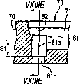
It is excessive big that the most serious problem is that the live load of boring drift becomes.Figure 18 C shows the state that has formed communications ports 81 in the elongate grooves part 71 of normal part 79.By making the boring drift bore the centre on the inclined-plane 82 be positioned at elongate grooves part 71 ends thoroughly or lower part more, form the first communications ports 81a with big cross section and closing bottom.Form the second communications ports 81b by the bottom that makes another boring drift enter the first communications ports 81a then, thereby finished communications ports 81 by two steps.The boring stroke S1 of boring drift that is applied to normal part 79 in above-mentioned situation is shorter, so the live load of boring drift is less relatively.
On the other hand, Figure 18 D shows the state of the communications ports 81 that forms in the elongate grooves part 71 in improper part 80.Because the boring drift is straight alignment, so if elongate grooves part 71 than the short difference in size D of designated length, forms the first communications ports 81a in the position near 82 upper ends, inclined-plane so.Therefore, boring stroke S2 is long more a lot of than boring stroke S1, makes to have applied very strong lateral stress on tiny boring drift.As a result, shortened the life-span of the boring drift that is used for improper part 80 greatly.And the fracture frequency of boring drift increases.The shortening in this life-span causes following situation, though promptly drift can be carried out the punching function well to normal part 79, they but can not be used for improper part 80.This is uneconomic, because need replacement drift more early.In addition, the frequent substitution of drift has reduced productivity ratio.
Figure 18 B shows the groove 83 that is formed to extend in the orientation of elongate grooves part 71.Groove 83 is set, is used for the clearly end of molding long and thin groove part 71, and be used to keep the top surface of plate of material 70 smooth.If there is not groove 83, so when the projection 74 of first mould 72 enters in the plate of material 70, elongate grooves part 71 vertically on the material of distortion will form the protuberance of indicating as the dotted line among this figure.This protuberance applies reaction force on the end of the projection 74 that is entering, the end of elongate grooves part 71 can clearly not form as a result.In addition, protuberance will reduce the flatness that cavity forms the plate top surface.The formation of groove 83 has solved the problems referred to above, will form wherein the material of being deformed to of protuberance because it has absorbed.
Summary of the invention
Therefore the purpose of this invention is to provide a kind of method of making jet head liquid, this jet head liquid longitudinal ends of all elongate grooves parts that can align through arranging, thus improve the jet performance of jet head liquid.
The live load that provides a kind of method of making jet head liquid, this jet head liquid can reduce to be used to bore communications ports and impose on drift also is provided purpose of the present invention, thereby prolongs the life-span of drift.
To achieve these goals, according to the present invention, a kind of method of making jet head liquid is provided, wherein said jet head liquid comes liquid droplets from jet hole by produce pressure oscillation in liquid, described liquid containing is in a plurality of pressure generation chambers that are communicated with described jet hole, and described method comprises the steps:
Sheet-metal component is provided;
First mould is provided, in described first mould, a plurality of projections be arranged on the first direction to form projection with constant spacing at least one arrange, each in the described projection is elongated on the second direction perpendicular to described first direction, described first mould is towards first of described board member;
Second mould is provided, and described second mould is relative with described first mould, support described board member simultaneously second;
On described board member, form at least one first area, so that described first area has the rigidity littler than another zone of described board member;
Make described first mould and second mould close, make described projection enter the second area on first of described board member, described projection pressurized on perpendicular to the third direction of described first direction and described second direction, to produce the plastic deformation of material among the gap that is limited between the described projection in the described board member, thereby form the groove that is separated out that will become described pressure generation chamber
Wherein, described at least one first area and described second area at least one end on first direction is adjacent, makes described first area and second area be arranged on the described second direction.
By this structure, the plastic deformation on second direction that takes place in the end on the first direction from second area is unrestricted, therefore can be so that near the groove that is separated out the align ends has the length of appointment.
In other words,, make to be far longer than its deflection on first direction, therefore can make " align ends " groove have the length of appointment in the amount of plastic deformation on the second direction according to the plastic deformation of first area.
In addition, because between the action period of first mould, allow plastic deformation on every side, so can clearly form the end of " align ends " groove on second direction in the first area.
Preferably, this method also is included in the step that forms through hole in each of the described groove that is separated out, and described through hole will become one passage in of being communicated with in the described pressure generation chamber and the described jet hole.Described through hole be formed on relative with described first area, the described groove that is separated out each near the end on the described second direction.
Because make that the in-position of boring drift is identical for the groove that is separated out, thus can be so that impose on the power minimum of boring drift, thus can prolong the life-span of boring drift.The cost relevant with machining tool can be for example saved in the life-time dilatation of boring drift, and prolongs the replacement cycle of boring drift.In addition because improved the formation precision of the groove that is separated out, so that the capacity of pressure generation chamber and shape homogeneous, thereby can improve the ink spray characteristic.
Preferably, arrange projection in described first mould forming two arrangements of described projection, and when described projection entered described board member, described first area was between two arrangements of described projection.
In this case, the length of two groups of grooves can be proofreaied and correct in a first area, and this is high efficiency.
Preferably, be formed with through hole or groove in the first area.In this case, can form the first area by simple punching out, thus simplified manufacturing technique.In addition, the deformation of first area just in time meets the plastic deformation on second direction that takes place from second area.
Preferably, the closer to the end of described second area on first direction, the distance between described first area and the described second area is short more.
In this case, can come the described distance of optimization according to the necessary amount of plastic deformation on second direction that takes place from second area.As a result, make the equal in length of the groove that is separated out, and vertically hold by straight alignment.
Here, preferably, described first area has trapezoidal shape, the feasible end of the more close described second area of longer side on described first direction.
In this case, arrive the first area immediately, thereby make the first area have maximum plastic deformation near the part of longer side from the plastic deformation of the end of second area on first direction.On the other hand,, can not arrive the first area immediately, thereby make the first area slight plastic deformation only take place near the part of shorter side from the plastic deformation of second area in part away from the end of second area on first direction.
Projection in arranging described first mould with the situation that forms two projection arrangement under, described trapezoidal shape is preferred with respect to a line symmetry of extending along described first direction.
Preferably, this method also comprises such step, promptly forms the groove that extends along described first direction, makes described first area be positioned at described groove.
In this case, groove guarantees enough flatnesses of board member and the length correction of " align ends " groove, thereby has simplified manufacturing process.
According to the present invention, a kind of jet head liquid also is provided, comprising:
Sheet-metal component comprises:
First, it has the first area, and described first area is formed with a plurality of grooves of arranging on first direction, and each in the described groove is elongated on the second direction perpendicular to described first direction; And
Second, it is formed with a plurality of holes, each in the described hole all with described groove in one be communicated with;
Elastic plate, it is attached to described first of described board member, forms described pressure generation chamber to seal described groove; And
Nozzle plate, it is attached to described second of described board member, and described nozzle plate is formed with from a plurality of jet holes of liquid droplets wherein, and one in each in the described jet hole and the described hole is communicated with,
Wherein, at least one an opening and described first area end on described first direction is adjacent, makes described first area and described aperture arrangement on described second direction.
Description of drawings
By the reference accompanying drawing preferred illustrative embodiment is described in detail, it is clearer that above-mentioned purpose of the present invention and advantage will become, wherein:
Fig. 1 is the perspective view according to the ink injection record head of the decomposition of first embodiment of the invention;
Fig. 2 is the profile of ink injection record head;
Fig. 3 A and 3B are the views that is used to explain vibrator units;
Fig. 4 is the plane that cavity forms plate;
Fig. 5 A is the enlarged drawing of X part among Fig. 4;
Fig. 5 B is the profile along Fig. 5 A center line VB-VB;
Fig. 5 C is the profile along Fig. 5 A center line VC-VC;
Fig. 6 is the plane of elastic plate;
Fig. 7 A is the enlarged drawing of Y part among Fig. 6;
Fig. 7 B is the profile along Fig. 7 A center line VIIB-VIIB;
Fig. 8 A and 8B are the views that is used to explain first mould that is used to form the elongate grooves part;
Fig. 9 A and 9B are the views that is used to explain second mould that is used to form the elongate grooves part;
Figure 10 A is the view that is used to explain the step that forms the elongate grooves part to Figure 10 C;
Figure 10 D is the plane of the position relation between explanation first mould and second mould;
Figure 11 shows the perspective view of the position relation between first mould, plate of material and second mould;
Figure 12 A is the plane that forms plate according to the cavity of first embodiment of the invention, shows to form elongate grooves part state before;
Figure 12 B is the profile of XIIB-XIIB along the line;
Figure 13 A is the plane that cavity forms plate, shows to form elongate grooves part state afterwards;
Figure 13 B is the profile of XIIIB-XIIIB along the line;
Figure 14 is used for explaining that the low rigidity section of cavity formation plate is the figure how to carry out deformation;
Figure 15 is the profile that forms plate according to the cavity of second embodiment of the invention;
Figure 16 is the profile that forms plate according to the cavity of third embodiment of the invention;
Figure 17 is the profile that forms plate according to the cavity of fourth embodiment of the invention;
Figure 18 A is included in the plane of the cavity formation plate in traditional jet head liquid;
Figure 18 B is the profile that the line XVIII-XVIII along Figure 18 A is got;
Figure 18 C is that the cavity of Figure 18 A forms the communications ports in the normal part of plate and the profile of elongate grooves part;
Figure 18 D is that the cavity of Figure 18 A forms the communications ports in the improper part of plate and the profile of elongate grooves part;
Figure 18 E is the profile that the line XVIIIE-XVIIIE along Figure 18 C is got; And
Figure 19 shows the profile that tradition is forged the relation between first mould, plate of material and second mould in the processing.
The specific embodiment
Hereinafter with reference to accompanying drawing embodiments of the invention are described.The structure of jet head liquid at first will be described.
Because the present invention is preferably applied to the record head of ink-jet recording apparatus, so above-mentioned record head as the representational example of jet head liquid is shown in an embodiment.
As depicted in figs. 1 and 2, record head 1 roughly by case 2, be included in case 2 inside vibrator units 3, be attached to the front end face of case 2 flow channel unit 4, be arranged into connecting plate 5 on the rear end face of case 2, the supply pin unit 6 that is fixed to the rear end face of case 2 constitutes.
Shown in Fig. 3 A and 3B, vibrator units 3 is roughly by piezoelectric vibrator group 7, the fixed head 8 that combines with piezoelectric vibrator group 7 be used to piezoelectric vibrator group 7 to provide to drive the flexible cable 9 of signal.
In addition, pseudo-vibrator 10a has than driving the enough wide width of vibrator 10b, and has function that protection driving vibrator 10b avoids clashing into etc. and the guidance function that vibrator units 3 is navigated to the precalculated position.
Be attached on the fixed head 8 by fixed end part, make its free end portion project into the outside of the front end face of fixed head 8 each piezoelectric vibrator 10.Being each piezoelectric vibrator 10 is supported on the fixed head 8 in the mode of cantilever.In addition, the free end portion of each piezoelectric vibrator 10 is made of alternately laminated piezoelectrics and interior electrode, with by apply between the electrode of opposite electrical potential difference come element vertically on extend or shrink.
Case 2 is the molded and shaped block member of thermosetting resin by epoxylite etc.Here, case 2 is molded and shaped by thermosetting resin to be because thermosetting resin has the mechanical strength that is higher than ordinary resin, and its linear expansion coefficient is less than ordinary resin, and is therefore little with the deformability of environment temperature.In addition, the inside of case 2 is formed with container chamber 12 that can hold vibrator units 3 and the ink feed passage 13 that constitutes the part of ink flow path.In addition, the front end face of case 2 is formed with the groove 15 that is used to constitute common ink pond 14.
Partly be recessed into by the front end face that makes case 2 and form groove 15, so that it has the trapezoidal basically shape that forms in a left side and the right outside of container chamber 12.
Connecting plate 5 is to be formed with to record head 1 to carry the wiring plate of the electric wire of various signals, and has the connector 17 that can connect signal cable.In addition, connecting plate 5 is disposed on the rear end face of case 2, and by the welding etc. be connected with the electric wire of flexible cable 9.In addition, the front end from the signal cable of control device (not shown) inserts connector 17.
Needle stand 18 is the members that are used for fixing ink feed pin 19, and its surface is formed with the pedestal 21 that is used for two ink feed pins 19, is used for fixing the proximal part of ink feed pin 19.Pedestal 21 manufactures circle according to the bottom shape of ink feed pin 19.In addition, the approximate centre of base bottom surface partly is formed with the ink discharge port 22 that penetrates on the plate thickness direction of needle stand 18.In addition, needle stand 18 is extending laterally out flange portion.
In addition, as shown in Figure 2, supply pin unit 6 is disposed in the rear end face of case 2.Under this arrangement states, the connectivity port 16 that the ink of supply pin unit 6 is discharged port 22 and case 2 is interconnected by the state of sealing ring 23 with the liquid sealing.
To explain above-mentioned flow channel unit 4 below.Flow channel unit 4 is made of following structure, and wherein nozzle plate 31 is attached on the face of cavity formation plate 30, and elastic plate 32 is attached on another face of cavity formation plate 30.
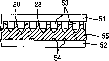
As shown in Figure 4, it is the tabular components that are made of metal that cavity forms plate 30, and this tabular component is formed with elongate grooves part 33, communications ports 34 and overflows groove part 35.According to embodiment, it is to be that the metal base of 0.35mm is made by the thickness that processing is made by nickel that cavity forms plate 30.
To explain the reason of the nickel system of selection metal base herein.First reason is that the linear expansion coefficient of nickel is basic identical with the linear expansion coefficient of the metal (as below with the stainless steel among the embodiment that mentions) of the major part that constitutes nozzle plate 31 and elastic plate 32.In other words, when the linear expansion coefficient of the cavity formation plate 30, elastic plate 32 and the nozzle plate 31 that constitute flow channel unit 4 was basic identical, when heating and adhering to each member, each member was evenly to expand.
Therefore, be difficult to produce the mechanical stresses such as warpage that the difference by expansion rate causes.So even when sticking temperature is set at high temperature, each member still can adhere to mutually and not have problems.In addition, even produce heats when piezoelectric vibrator in operation note 1 10, and flow channel unit 4 is when being heated by heat, and each member 30,31 and 32 that constitutes flow channel unit 4 still evenly expands.Therefore, even when the heating of following activated 1 repeatedly with when following the cooling of the record head 1 of stopping using, also be difficult in each member 30,31 and 32 that constitutes flow channel unit 4, cause the defective of peeling off etc.
Second reason is that nickel has excellent corrosion resistance.In other words, in the record head 1 of this class, preferably use moisture ink, so even importantly after record head 1 and water Long contact time, still can not cause alteration such as corrosion.In this respect, nickel is similar to stainless steel, has fabulous corrosion resistance, and alterations such as corrosion are difficult to take place.
The 3rd reason is that nickel has good ductility.Promptly will mention, when making cavity formation plate 30, make by plastic working (as forging) as the back.In addition, being formed on cavity, to form the shape of elongate grooves part 33 in the plate 30 and communications ports 34 minimum, and need high dimensional accuracy.When nickel is used as metal base, because the ductility of nickel is good, so even elongate grooves part 33 and communications ports 34 also can form with high dimensional accuracy by plastic working.
In addition, form plate 30 for cavity, when the condition of the condition of the condition of linear expansion coefficient, corrosion resistance and ductility was met, cavity formed plate 30 and also can be made of the metal outside the nickel.
In addition, because the wall thickness of the end portion of partition wall 28 as thin as a wafer, so, still can guarantee required capacity even form each pressure generation chamber 29 thick and fast.
Two vertical end portion of elongate grooves part 33 all inwards tilt downwards when depth side is advanced.Two end portion all constitute by this way, to form elongate grooves part 33 by plastic working with the excellent size precision.
In addition, the elongate grooves part 33 adjacent to the two ends of going is formed with independent pseudo-groove 36, and this pseudo-groove 36 has the width of being wider than elongate grooves part 33.Pseudo-groove part 36 is groove parts of channel form, and this groove part constitutes and the irrelevant pseudo-pressure generation chamber of the injection of ink droplet.By wide about 0.2mm, be about 1.5mm according to the pseudo-groove part 36 of embodiment, the groove of about deeply 0.1mm constitutes.In addition, the bottom surface of pseudo-groove part 36 is recessed into W shape.This also is in order to increase the rigidity of partition wall 28, and forms pseudo-groove part 36 by plastic working with the excellent size precision.
In addition, delegation's groove is made of each elongate grooves part 33 and a pair of pseudo-groove part 36.
According to embodiment, form two row grooves as shown in Figure 4.
In addition, the area of section of first communications ports 37 and second communications ports 38 differs from one another, and the inside dimension of second communications ports 38 is provided with slightly forr a short time than the inside dimension of first communications ports 37.This causes owing to making communications ports 34 by extruding.Cavity form plate 30 by processing thickness be the nickel plate of 0.35mm and manufactured, even deduct the degree of depth of groove part 33, the length of communications ports 34 also is equal to, or greater than 0.25mm.In addition, the width of communications ports 34 need be littler than the recess width of elongate grooves part 33, is set to less than 0.1mm.So when communications ports 34 will just be finished punching out by time processing, formpiston (drift) was curved owing to its depth-to-width ratio.
So in an embodiment, processing is divided into two steps.In the first step, first communications ports 37 in second step, forms second communications ports 38 in half formation of plate thickness direction.The processing technology of this communications ports 34 will be described in the back.
In addition, pseudo-groove part 36 is formed with pseudo-communications ports 39.Similar to above-mentioned communications ports 34, pseudo-communications ports 39 comprises the first pseudo-communications ports 40 and the second pseudo-communications ports 41, and the inside dimension of the second pseudo-communications ports 41 is set to littler than the inside dimension of the first pseudo-communications ports 40.
In addition, though according to embodiment, the opening shape of for example understanding communications ports 34 and pseudo-communications ports 39 is that the tiny through hole by rectangle constitutes, and the present invention is not limited to this shape.For example, this shape can be made of the through hole of circular open or the through hole of polygonal-shaped openings.
Next, will explain above-mentioned elastic plate 32.Elastic plate 32 is a kind of sealing plates of the present invention, and for example by the composite manufacturing, this composite has one deck elastic membrane 43 is laminated to double-decker on the gripper shoe 42.According to embodiment, adopt corrosion resistant plate as gripper shoe 42, PPS (polyphenylene sulfide) is as elastic membrane 43.
As shown in Figure 6, elastic plate 32 is formed with membrane portions 44, ink feed port 45 and flexible portion 46.
Shown in Fig. 7 B, the part corresponding with elongate grooves part 33 of removing gripper shoe 42 by methods such as etchings make membrane portions 44, and the inside of ring forms island part 47 only to stay elastic membrane 43.Island part 47 is to be used for the part that combines with the terminal surface of piezoelectric vibrator 10.
Reason with small through hole formation ink feed port 45 is to provide the flow channel resistance between pressure generation chamber 29 and common ink pond 14 by this way.That is,, impose in the pressure generation chamber 29 pressure of inks by utilization and change and spray ink droplet according to record head 1.Therefore, in order to spray ink droplet efficiently, it is important to stop as far as possible pressure generation chamber 29 interior ink pressures to escape into a side in common ink pond 14.From this viewpoint, ink feed port 45 is made of small through hole.
In addition, when constituting by through hole, has the advantage that is easy to process and obtain high dimensional accuracy as embodiment ink inside supply port 45.That is, ink feed port 45 is through holes, can make by Laser Processing.Therefore, though minor diameter also can make with high accuracy, and the operation also easy.
In addition, the gripper shoe 42 and the elastic membrane 43 of formation elastic plate 32 are not limited to described example.And polyimides can be used as elastic membrane 43.And elastic plate 32 can be made of following metallic plate, and described metallic plate has heavy wall, be used to the thin-walled that constitutes the thin-walled of membrane portions 44 and be used to constitute flexible portion 46 around the described heavy wall.
In addition, when a surface that above-mentioned elastic plate 32 and cavity is formed plate 30 combines, when promptly combining with the face that is used to form elongate grooves part 33 of cavity formation plate 30, the opening surface of membrane portions 44 sealing elongate grooves parts 33 is to form the separation to pressure generation chamber 29.Similarly, seal the opening surface of pseudo-groove part 36, to form separation to pseudo-pressure generation chamber.In addition, when another surface that nozzle plate 31 and cavity is formed plate 30 combined, jet hole 48 was towards corresponding communications ports 34.When the piezoelectric vibrator 10 that is attached to island part 47 is stretched or is compressed under this state, deformation takes place in the elastic membrane 43 around the island part, and island part 47 is pushed to elongate grooves part 33 1 sides or tension on the direction of leaving elongate grooves part 33 1 sides.By making elastic membrane 43 that deformation take place, pressure generation chamber 29 is expanded or compresses, and provides pressure to change with the ink in pressure generation chamber 29.
When with elastic plate 32 (that is, flow channel unit 4) when being attached on the case 2, flexible portion 46 sealed grooves 15.Flexible portion 46 absorbs the pressure that is stored in the ink in the common ink pond 14 to be changed.That is, deformation takes place in elastic membrane 43 pressure according to the ink of being stored.In addition, the above-mentioned groove part 35 that overflows is formed for the space that allows elastic membrane 43 to be expanded.
Record head 1 with said structure comprises the public ink flow channel from ink feed pin 19 to common ink pond 14 and 14 arrives the individual ink flow channels of each jet hole 48 by pressure generation chamber 29 from the common ink pond.In addition, the ink that is stored in the print cartridge is introduced into from ink feed pin 19, and is stored in the common ink pond 14 by the public ink flow channel.Be stored in ink in the common ink pond 14 by individual ink passage injected going out from jet hole 48.
For example, when piezoelectric vibrator 10 is compressed, membrane portions 44 be pulled to vibrator units 3 that side so that pressure generation chamber 29 expand.By this expansion, pressure generation chamber 29 inside are under the negative pressure, and the ink in the common ink pond 14 flows to each pressure generation chamber 29 by ink feed port 45.After this, when piezoelectric vibrator 10 was stretched, membrane portions 44 was pulled to cavity and forms that side of plate 30 so that 29 contractions of pressure generation chamber.Shrink by this, the ink pressure in the pressure generation chamber 29 rises, and ejects ink droplet from the jet hole 48 of correspondence.
According to record head 1, make the bottom surface (elongate grooves part 33) of pressure generation chamber 29 recessed with V-arrangement.So it is big to be used for the wall thickness of its end portion of wall ratio of proximal part of partition wall 28 of separating adjacent pressure generation chamber 29.Thereby the rigidity of heavy wall 28 can be increased.Therefore, when spraying ink droplet, even when having produced the ink pressure variation in the pressure generation chamber 29, this pressure variation also is difficult to be passed to adjacent pressure generation chamber 29.As a result, can prevent the so-called adjacent injection of crosstalking and can stablize ink droplet.
According to embodiment, the ink feed port 45 that is used to be communicated with common ink pond 14 and pressure generation chamber 29 is made of the aperture that penetrates elastic plate 32 on the thickness of slab direction, can easily realize the dimensional accuracy that it is high by Laser Processing or similar approach.Therefore, the ink flow behavior (flow velocity, flow etc.) in each pressure generation chamber 29 can be highly equal.In addition, when realizing this manufacturing, also make this easy to manufacture by laser beam.
According to embodiment, provide the pseudo-pressure generation chamber irrelevant and adjacent (promptly with the pressure generation chamber 29 that is positioned at capable end portion with ink droplet jet, the hollow space that is separated out by pseudo-groove part 36 and elastic plate 32), for pressure generation chamber 29 at two ends, the one side is formed with adjacent pressure generation chamber 29, and its opposite side is formed with pseudo-pressure generation chamber.So,, can make the equal stiffness of partition wall of other pressure generation chamber 29 of the rigidity of the partition wall of separating pressure generation chamber 29 and interline for the pressure generation chamber 29 that is positioned at capable end portion.As a result, the droplet ejection characteristics with all the pressure generation chambers 29 in the delegation can be equal to each other.
For pseudo-pressure generation chamber, its width in orientation is bigger than the width of each pressure generation chamber 29.In other words, the width of pseudo-groove part 36 is bigger than the width of elongate grooves part 33.Therefore, going the spray characteristic of pressure generation chamber 29 of the pressure generation chamber 29 of end portion and interline can equate each other accurately.
According to embodiment, partly be recessed into by the front end face that makes case 2 and form groove 15, be separated to form common ink pond 14 by groove 15 and elastic plate 32, can form common ink pond 14 without special-purpose member, and realize the simplification of structure.In addition, by resin molded manufacturing case 2, make the manufacturing of groove 15 also relatively easy.
Next, the method for making record head 1 will be explained.Because being characterised in that, described manufacture method makes the step that cavity forms plate 30, so will mainly provide explanation to the step of making cavity formation plate 30.
Make cavity and form plate 30 by forging by progressive die.In addition, the metal batten 55 (being called " batten 55 " in the following description) that is used as the material of cavity formation plate 30 is made by nickel as described above.
The step of making cavity formation plate 30 comprises the step of making elongate grooves part 33 and the step of making communications ports 34, and it is undertaken by progressive die (progressive die).
Partly form in the step in elongate grooves, used formpiston 51 and the former shown in Fig. 9 A and Fig. 9 B shown in Fig. 8 A and Fig. 8 B.Formpiston 51 is the moulds that are used to form elongate grooves part 33.Be arranged with on the formpiston and be used to form elongate grooves part 33 and the same number of projection 53 number and elongate grooves part 33.In addition, the projection 53 that is positioned at two ends in orientation also is provided with the pseudopods (not shown) that is used to form pseudo-groove part 36.Shown in Fig. 8 B, the end portion 53a of projection 53 is tapered with about miter angle from its middle broad ways.Therefore, from its length direction, end portion 53a sharpening forming V-shape.In addition, shown in Fig. 8 A, vertically hold 53c all to be tapered for two of end portion 53a with about miter angle.Therefore, the end portion 53a of projection 53 forms the tapered triangular prism shape in two ends.Form the inclined-plane 33b (seeing Fig. 5 b) of the longitudinal end of elongate grooves part 33 by tapered part 53c.
In addition, former 52 is formed with a plurality of projections 54 in the above.Projection 54 is used for the auxiliary partition wall that forms separating adjacent pressure generation chamber 29, and between elongate grooves part 33.Projection 54 is the quadrangular prism shape, and its width is set to be narrower than slightly the gap (thickness of partition) between the adjacent pressure generation chamber 29, and it highly is set to identical with its width.It is identical with the length of elongate grooves part 33 (projection 53) that the length of projection 54 is set to.
In the step that elongate grooves partly forms, at first, shown in Figure 10 A, batten 55 be placed in former 52 above, formpiston 51 is disposed in the upside of batten 55.Then, shown in Figure 10 B, the end portion that formpiston 51 moves down to promote projection 53 enters batten 55.At this moment, because the end portion 53a sharpening forming V-shape of projection 53, end portion 53a can firmly be advanced in the batten 55 and can be crooked.Shown in Figure 10 C, projection 53 is advanced to the middle part of batten 55 along the thickness direction of plate.
By promoting projection 53, the part distortion of batten 55 is to form elongate grooves part 33.At this moment, because the end portion 53a sharpening forming V-shape of projection 53, so also can form with high dimensional accuracy even have the elongate grooves part 33 of very little shape.That is, the part of the batten 55 that is promoted by end portion 53a is out of shape smoothly, and the elongate grooves part 33 that form is formed according to the shape of projection 53.In addition, because two longitudinal end 53c of end portion 53a are tapered, so the batten 55 that is promoted by described part also is out of shape smoothly.Therefore, the two end portions longitudinally of elongate grooves part 33 also all forms inclined-plane 33b as shown in Figure 10 D with high dimensional accuracy.
Because the promotion of projection 53 is stopped at the centre of plate thickness direction, be thicker than the batten 55 that forms under the through hole situation so can use.Therefore, the rigidity that cavity forms plate 30 can increase, and the ink spray characteristic can be improved.In addition, cavity forms that plate 30 can easily be disposed and described operation also is useful for increasing the plane accuracy.
The extruding of the part of batten 55 by projection 53 rises in the space between the adjacent projection 53.In this case, the projection 54 that provides on the former 52 be arranged on and projection 53 between interval corresponding position, helped the distortion of batten 55 in the space.Therefore, batten 55 can be introduced into the space between the projection 53 effectively, and outstanding (being partition wall 28) can form higherly.
Figure 11 shows the position relation between first mould 51, second mould 52 and the plate of material 55.
Arrange elongate grooves part 33 to form two arrangements of elongate grooves part 33.
Use first mould 51 and 52 pairs of battens of second mould (plate of material) 55 to carry out above-mentioned plastic working at normal temperatures.Similarly, the plastic working that will be described below at normal temperatures.
It is mobile material plate 55 in the order forging apparatus how that Figure 12 shows.Transferring material plate 55 sequentially to the right in the figure.In precasting process 63, on nickel material plate 55, carry out various borings, groove formation etc.Formed general structure is to overflow groove part 35.Form elongate grooves part 33 by the main technology of carrying out in precasting process 63 backs 64.
By the dotted line region surrounded among Figure 12 is the place that the arrangement 33a that will become the elongate grooves part 33 of pressure generation chamber 29 and pseudo-groove part 36 will form.
In precasting process, the parts between two arrangement 33a of elongate grooves part 33 are formed on the groove 83 that extends in the orientation of elongate grooves part 33.As above described with reference to Figure 18 A and Figure 18 B, provide groove 83 to form enough flatnesses of plate 30 to guarantee cavity, and the longitudinal end that is used for clearly forming elongate grooves part 33.
In this embodiment, pseudo-groove part 36 and near four elongate grooves parts 33 arrangement 33a end are corresponding to the improper part 80 shown in Figure 18 A.These groove parts 33,36 are called " align ends " elongate grooves part. Elongate grooves part 33 and 36 vertically on be separated by with the end of five align ends elongate grooves parts 33 and 36 and set in advance low rigidity section 61 on the position of distance to a declared goal.Shown in Figure 12 B, the low rigidity section 61 of this embodiment is trapezoid-shaped openings 62 of penetrable material plate 55.Trapezoidal shape is symmetrical with respect to the center line that it extends along the orientation of elongate grooves part 33, and longer side 62a is positioned at pseudo-groove part 36 1 sides.
Carry out punching by bottom 83a and form trapezoid-shaped openings 62 preformed groove 83.Therefore, the execution sequence of manufacturing step is such, promptly after the punching out of sequentially carrying out as the formation of the groove 83 of precasting process and opening 62, carry out the formation of the elongate grooves part 33 by first mould 51 and the formation of communications ports 34 and pseudo-communications ports 39 as main technology.
Set width, length and the degree of depth of size to be suitable for elongate grooves part 33 and 36 of trapezoid-shaped openings 62, cavity forms thickness and other factors of plate 30.In this embodiment, the length of longer side 62a and shorter side 62b is respectively 0.86mm and 0.48mm, and the distance between longer side 62a and the shorter side 62b is 0.73mm.
In trapezoidal shape, the limit 62c that connects longer side 62a and shorter side 62b tilts with respect to the orientation of elongate grooves part 33.By this structure, along with the more close pseudo-groove part 36 in position, the distance between the vertical end of align ends groove part 33 (36) and the relative edge 62c of low rigidity section 61 reduces gradually.
After forming opening 62, to shown in Figure 10 D, extrusion chamber forms plate 30 between first mould 51 and second mould 52 as Figure 10 A, thereby forms elongate grooves part 33 and 36.Then, bore the inclined-plane 33b (comparing) of elongate grooves part 33 longitudinal ends with the boring drift, thereby form communications ports 34 and 39 with Figure 18 C.The position of opening 62 is near that side that forms communications ports 34 and 39.
To enumerate the advantage that obtains by above-mentioned structure below.
When forming plate 30 by first mould 51 and second mould, 52 extrusion chambers, align ends elongate grooves part 33 and 36 take place plastic deformations and they vertically on move.In company with plastic deformation, material arrives the limit 62c of opening 62, thereby makes limit 62c that deformation take place.Therefore, be unrestricted from align ends elongate grooves part 33 and 36 plastic deformations that take place the vertical of them, therefore can be so that align ends elongate grooves part 33 and 36 has the length of appointment.
In other words, plastic deformation according to opening 62, make align ends elongate grooves part 33 and 36 amount of plastic deformation in the vertical be far longer than the deflection in its orientation, therefore can make align ends elongate grooves part 33 and 36 have the length of appointment.
In addition, because between the action period of first mould 51, around opening 62, allow above-mentioned plastic deformation, so can clearly form the longitudinal end of align ends elongate grooves part 33 and 36.
As a result, when communications ports 34 that will be communicated with jet hole 48 and pseudo-communications ports 39, make that the in-position of boring drift is identical for elongate grooves part 33 and 36 in the formation of the end of elongate grooves part 33 and 36.By the in-position being arranged on the as far as possible little position of live load, can prolong the life-span of boring drift.The cost relevant with machining tool can be for example saved in the life-time dilatation of boring drift, and prolongs the replacement cycle of boring drift.In addition because improved the formation precision of elongate grooves part 33 and 36, so that the capacity of pressure generation chamber 29 and shape homogeneous, thereby can improve the ink spray characteristic.
Figure 14 shows trapezoid-shaped openings 62 is how to carry out deformation when forming elongate grooves part 33 and 36.Solid line and dotted line are indicated respectively before the formation of elongate grooves part 33 and 36 and shape afterwards.During the formation of elongate grooves part 33 and 36, they vertically on from elongate grooves part 33 and 36 plastic deformations that take place two limit 62c are inwardly pushed away, thereby make 62c deformation plastically in limit become bent limit 62c '.When from two thruster limit 62c, pressure changes the component that points to shorter side 62b into, thereby makes shorter side 62b move down (as shown in figure 14) to become the shorter side 62b ' shorter than the shorter side 62b that deformation does not take place.
Therefore, after deformation took place, trapezoid-shaped openings 62 had narrower shape, and this shape can be passed through to obtain from the initial trapezoid-shaped openings 62 of two thrusters, and this shape is still with respect to its center line symmetry of extending along the orientation of elongate grooves part 33.As mentioned above, the longer side 62a of opening 62 is positioned at pseudo-groove part 36 1 sides, and limit 62c tilts.Therefore, when the stress of plastic deformation from double side acting during in opening 62, deformation take place to be elongated towards shorter side 62b in trapezoid-shaped openings 62, become longer and narrower shape.The deformation of opening 62 just in time meets the plastic deformation from elongate grooves part 33 and 36, so vertical end of align ends elongate grooves part 33 and 36 is straight alignment.
Because deformation takes place in opening 62, so the profile of groove 83 curves inwardly near opening 62, as shown in FIG. 13A.In the figure, by the sweep of symbol 83b indication profile, and exaggerated flexibility so that understand.
Because opening 62 is set in communications ports 34 that forms with the end that will pass elongate grooves part 33 and 36 and 39 more close sides, so form well at the inclined-plane 33b of a side that will form communications ports 34 and 39 and the part of elongate grooves part 33 and 36, that is the length and the shape that, have appointment respectively.Therefore, the end that can pass all elongate grooves parts 33 and 36 suitably forms communications ports 34 and 39 on the position of homogeneous.
Because opening 62 is arranged between two arrangement 33a of elongate grooves part, so just can proofread and correct two groups of improper elongate grooves length partly by an opening 62, this is high efficiency.
Because opening 62 penetrates cavity and forms plate 30, thus can form opening 62 by simple punching as the part of precasting process, thus simplified manufacturing technique.In addition, the deformation of opening 62 just in time meets the plastic deformation that takes place in the vertical from elongate grooves part 36.
Because opening 62 has trapezoidal shape, so that the distance between vertical end of the limit 62c of opening 62 and pseudo-groove part 36 (plastic deformation is bigger herein) is shorter.Therefore, arrive opening 62 immediately, thereby make opening 62 have maximum plastic deformation near the part of longer side 62a from the plastic deformation of pseudo-groove part 36.On the other hand, because make limit 62c and longer away from the distance between vertical end of the elongate grooves part 33 (plastic deformation is less herein) of pseudo-groove part 36, so the plastic deformation from these elongate grooves parts 33 can not arrive opening 62 immediately, thereby make opening 62 slight plastic deformation only take place near the part of shorter side 62b.
In other words, according to coming setpoint distance in its necessary amount of plastic deformation that vertically takes place from elongate grooves part 33 and 36.As a result, make the equal in length of elongate grooves part 33 and 36, and the straight alignment of longitudinal end.
Because opening 62 forms in the groove 83 that extends along the orientation of elongate grooves part 33 and 36, so a groove 83 has just guaranteed that cavity forms enough flatnesses of plate 30 and the length of improper elongate grooves part is proofreaied and correct, thereby has simplified manufacturing process.
Because set the position relation between opening 62 and elongate grooves part 33 and 36 accurately, so opening 62 usefulness can be acted on the align member of plastic working.
In order to obtain aforesaid same advantage, as shown in figure 15, can form plate 30 at its thickness direction fovea superior and then will hang down rigidity section 61 and form groove 63 by making cavity, rather than the opening 62 of take-through plate 30.When taking place from elongate grooves part 33 and 36 in its plastic deformation on vertically, deformation enter groove 63 with the both sides from groove 63 space takes place in plate 30.Thereby permission plastic deformation.
Because by making cavity form plate 30 at its thickness direction fovea superior and then form groove 63, thus its can form by the simple press process in the precasting process, therefore can simplified manufacturing technique.Owing to its recessed shape, suitably select the degree of depth of groove 63 to allow groove 63 deformation that takes place just in time to be met the plastic deformation on it is vertical that takes place from elongate grooves part 33 and 36.
In addition, though according to the above embodiments, shown the example that the present invention is applied to the record head that is used for ink-jet recording apparatus, but the object of using jet head liquid of the present invention not only comprises the ink of ink-jet recording apparatus, can also be glue, nail polish (manicure), conducting liquid (liquid metals) etc.
For example, the present invention can be applicable to be used to make the colored filter manufacturing installation of the colored filter of LCD.In this case, the color material injector head of this device is an example of jet head liquid.Another example of liquid injection apparatus is that the electrode that is used to form electrode (as the electrode of OLED display or FED (Field Emission Display)) forms device.In this case, the electrode material of this device (conduction is stuck with paste) injector head is an example of jet head liquid.Another example of liquid injection apparatus is the biochip making equipment that is used to make biochip.In this case, the sample injector head of the accurate pipette use of the biological organic substance injector head of this device and conduct is the example of jet head liquid.Liquid injection apparatus of the present invention comprises other industrial liquid injection apparatus of commercial Application.
Claims (11)
1. method of making jet head liquid, wherein said jet head liquid comes liquid droplets from jet hole by produce pressure oscillation in liquid, described liquid containing is in a plurality of pressure generation chambers that are communicated with described jet hole, and described method comprises the steps:
Sheet-metal component is provided;
First mould is provided, in described first mould, a plurality of projections be arranged on the first direction to form projection with constant spacing at least one arrange, each in the described projection is elongated on the second direction perpendicular to described first direction, described first mould is towards first of described board member;
Second mould is provided, and described second mould is relative with described first mould, support described board member simultaneously second;
On described board member, form at least one first area, so that described first area has the rigidity littler than another zone of described board member;
Make described first mould and second mould close, make described projection enter the second area on described first of described board member, described projection pressurized on perpendicular to the third direction of described first direction and described second direction, to produce the plastic deformation of material among the gap that is limited between the described projection in the described board member, thereby form the groove that is separated out that will become described pressure generation chamber
Wherein, described at least one first area and described second area at least one end on described first direction is adjacent, makes described first area and second area be arranged on the described second direction.
2. manufacture method as claimed in claim 1 also is included in the step that forms through hole in each of the described groove that is separated out, and described through hole will become one passage in of being communicated with in the described pressure generation chamber and the described jet hole,
Wherein, described through hole be formed on relative with described first area, the described groove that is separated out each near the end on the described second direction.
3. manufacture method as claimed in claim 1, wherein:
Arrange that described projection in described first mould is to form two arrangements of described projection; And
When described projection entered described board member, described first area was between two arrangements of described projection.
4. manufacture method as claimed in claim 1 wherein, forms through hole in described first area.
5. manufacture method as claimed in claim 1 wherein, forms groove in described first area.
6. manufacture method as claimed in claim 1, wherein, the closer to the end of described second area on described first direction, the distance between described first area and the described second area becomes short more.
7. manufacture method as claimed in claim 6, wherein, described first area has trapezoidal shape, the feasible described end of the more close described second area of longer side on described first direction.
8. manufacture method as claimed in claim 6, wherein,
Arrange that described projection in described first mould is to form two arrangements of described projection; And
Described trapezoidal shape is symmetrical with respect to a line that extends along described first direction.
9. manufacture method as claimed in claim 1 also comprises such step, promptly forms the groove that extends along described first direction, makes described first area be positioned at described groove.
10. jet head liquid comprises:
Sheet-metal component comprises:
First, it has two zones, in the described zone each is formed with a plurality of grooves of arranging on first direction, described two area arrangements are on the second direction perpendicular to described first direction, and each in the described groove is elongated on described second direction; And
Second, it is formed with a plurality of holes, each in the described hole all with described groove in one be communicated with;
Elastic plate, it is attached to described first of described board member, forms the pressure generation chamber to seal described groove; And
Nozzle plate, it is attached to described second of described board member, and described nozzle plate is formed with from a plurality of jet holes of liquid droplets wherein, and one in each in the described jet hole and the described hole is communicated with,
Wherein, at least one opening and described zone at least one end on described first direction is adjacent, makes described two zones and described aperture arrangement on described second direction, and described aperture arrangement is between described two zones.
11. jet head liquid as claimed in claim 10, wherein, described opening has the shape with respect to the straight line symmetry of extending along described first direction.
Applications Claiming Priority (2)
| Application Number | Priority Date | Filing Date | Title |
|---|---|---|---|
| JP2003292467A JP4729840B2 (en) | 2003-08-12 | 2003-08-12 | Method of manufacturing liquid jet head and liquid jet head obtained thereby |
| JP292467/2003 | 2003-08-12 |
Publications (2)
| Publication Number | Publication Date |
|---|---|
| CN1579780A CN1579780A (en) | 2005-02-16 |
| CN1299907C true CN1299907C (en) | 2007-02-14 |
Family
ID=34269057
Family Applications (1)
| Application Number | Title | Priority Date | Filing Date |
|---|---|---|---|
| CNB2004100551797A Expired - Fee Related CN1299907C (en) | 2003-08-12 | 2004-08-12 | Liquid jetting head and production method thereof |
Country Status (3)
| Country | Link |
|---|---|
| US (1) | US7249484B2 (en) |
| JP (1) | JP4729840B2 (en) |
| CN (1) | CN1299907C (en) |
Families Citing this family (3)
| Publication number | Priority date | Publication date | Assignee | Title |
|---|---|---|---|---|
| JP4333236B2 (en) * | 2003-07-03 | 2009-09-16 | セイコーエプソン株式会社 | Method of manufacturing mold for manufacturing liquid jet head and material block thereof |
| JP4604471B2 (en) * | 2003-08-12 | 2011-01-05 | セイコーエプソン株式会社 | Method of manufacturing liquid jet head and liquid jet head obtained thereby |
| JP4639718B2 (en) * | 2004-09-22 | 2011-02-23 | セイコーエプソン株式会社 | Pressure generating chamber forming plate manufacturing apparatus for liquid ejecting head, pressure generating chamber forming plate manufacturing method for liquid ejecting head, and liquid ejecting head |
Citations (4)
| Publication number | Priority date | Publication date | Assignee | Title |
|---|---|---|---|---|
| US5144709A (en) * | 1991-05-03 | 1992-09-08 | Olin Corporation | Formation of shapes in a metal workpiece |
| JPH06191043A (en) * | 1992-12-24 | 1994-07-12 | Ricoh Co Ltd | Production of nozzle plate of ink jet head |
| US6332671B1 (en) * | 1998-12-14 | 2001-12-25 | Seiko Epson Corporation | Ink jet recording head and method of manufacturing the same |
| US6499836B1 (en) * | 1999-01-12 | 2002-12-31 | Seiko Epson Corporation | Piezoelectric ink jet recording head formed by press working |
Family Cites Families (7)
| Publication number | Priority date | Publication date | Assignee | Title |
|---|---|---|---|---|
| US3338084A (en) * | 1965-02-23 | 1967-08-29 | Sr Clifford F Stegman | Method and apparatus for producing coins |
| DE4404837A1 (en) * | 1994-02-16 | 1995-08-17 | Behr Gmbh & Co | Rib for heat exchangers |
| EP0994398B1 (en) * | 1998-10-15 | 2009-01-21 | ETA SA Manufacture Horlogère Suisse | Method for manufacturing a gear wheel for a timepiece and gear wheel manufactured by said method |
| US6189363B1 (en) * | 1999-10-13 | 2001-02-20 | Yaw-Huey Lai | Structure of molding tool for manufacturing cooling fins |
| JP2002292868A (en) * | 2001-03-28 | 2002-10-09 | Ricoh Co Ltd | Liquid drop ejection head, ink cartridge and ink jet recorder |
| JP2003231259A (en) * | 2001-12-03 | 2003-08-19 | Seiko Epson Corp | Nozzle plate, its manufacturing method, and liquid ejection head |
| JP4604471B2 (en) * | 2003-08-12 | 2011-01-05 | セイコーエプソン株式会社 | Method of manufacturing liquid jet head and liquid jet head obtained thereby |
-
2003
- 2003-08-12 JP JP2003292467A patent/JP4729840B2/en not_active Expired - Fee Related
-
2004
- 2004-08-11 US US10/915,713 patent/US7249484B2/en not_active Expired - Fee Related
- 2004-08-12 CN CNB2004100551797A patent/CN1299907C/en not_active Expired - Fee Related
Patent Citations (4)
| Publication number | Priority date | Publication date | Assignee | Title |
|---|---|---|---|---|
| US5144709A (en) * | 1991-05-03 | 1992-09-08 | Olin Corporation | Formation of shapes in a metal workpiece |
| JPH06191043A (en) * | 1992-12-24 | 1994-07-12 | Ricoh Co Ltd | Production of nozzle plate of ink jet head |
| US6332671B1 (en) * | 1998-12-14 | 2001-12-25 | Seiko Epson Corporation | Ink jet recording head and method of manufacturing the same |
| US6499836B1 (en) * | 1999-01-12 | 2002-12-31 | Seiko Epson Corporation | Piezoelectric ink jet recording head formed by press working |
Also Published As
| Publication number | Publication date |
|---|---|
| US7249484B2 (en) | 2007-07-31 |
| CN1579780A (en) | 2005-02-16 |
| JP2005059393A (en) | 2005-03-10 |
| US20050057615A1 (en) | 2005-03-17 |
| JP4729840B2 (en) | 2011-07-20 |
Similar Documents
| Publication | Publication Date | Title |
|---|---|---|
| CN1219645C (en) | Liquid spray head and its manufacturing method | |
| CN1856403A (en) | Liquid injection head and method of producing the same and liquid injection device | |
| CN1240542C (en) | Liquid jet nozzle and liquid jetting device | |
| CN1253314C (en) | Liquid jetting head and producing method thereof | |
| CN1250398C (en) | Ink jet head, manufacturing method of ink jet head and ink jet printer having ink jet head | |
| CN1286647C (en) | Method for punching small holes and method for making liquid spraying head thereby | |
| CN1169670C (en) | Ink jet head and ink jet recording device | |
| CN2837074Y (en) | Ink jet head and filter plate of ink jet head | |
| CN2797037Y (en) | Ink jet head printing device | |
| CN1576008A (en) | Liquid injection head and producing method thereof and die used in the same method | |
| CN1749013A (en) | Method of working small recess portion, method of fabricating liquid ejection head and liquid ejection head | |
| CN1840270A (en) | Method for producing perforated work plate, perforated work plate, liquid-jet head and liquid-jet apparatus | |
| CN1269647C (en) | Liquid ejection head, and method of manufacturing the same | |
| CN101045382A (en) | Method for producing piezoelectric actuator, method for producing liquid droplet jetting apparatus, piezoelectric actuator, and liquid droplet jetting apparatus | |
| CN100404258C (en) | Working method for forming minute holes, tool used in the method, method and apparatus for manufacturing liquid ejecting head | |
| CN1654214A (en) | Head module, liquid jet device, method of manufacturing the head module, and method of manufacturing the liquid jet device | |
| CN1299907C (en) | Liquid jetting head and production method thereof | |
| CN1299908C (en) | Liquid jetting head and production method thereof | |
| CN1592975A (en) | Layered piezoelectric element realizing stable operating characteristic for high quality image recording | |
| CN1660691A (en) | Fluid actuating apparatus and method for manufacturing a fluid actuating apparatus, and electrostatically-actuated fluid discharge apparatus and process for producing an electrostatically-actuated flu | |
| CN1282548C (en) | Forging forcer, liquid jet head making method using the forging forcer and liquid jet head | |
| CN1259192C (en) | Liquid spray nozzle and its making method | |
| CN1751886A (en) | Apparatus of fabricating and method of fabricating liquid ejection head, and liquid ejection head | |
| CN1612808A (en) | Piezoelectric actuator and fluid injection head having the same | |
| CN1280099C (en) | Ink-jet head |
Legal Events
| Date | Code | Title | Description |
|---|---|---|---|
| C06 | Publication | ||
| PB01 | Publication | ||
| C10 | Entry into substantive examination | ||
| SE01 | Entry into force of request for substantive examination | ||
| C14 | Grant of patent or utility model | ||
| GR01 | Patent grant | ||
| CF01 | Termination of patent right due to non-payment of annual fee | ||
| CF01 | Termination of patent right due to non-payment of annual fee |
Granted publication date: 20070214 Termination date: 20180812 |