CN1299780C - System and method for physiologial drainage - Google Patents
System and method for physiologial drainage Download PDFInfo
- Publication number
- CN1299780C CN1299780C CNB018181945A CN01818194A CN1299780C CN 1299780 C CN1299780 C CN 1299780C CN B018181945 A CNB018181945 A CN B018181945A CN 01818194 A CN01818194 A CN 01818194A CN 1299780 C CN1299780 C CN 1299780C
- Authority
- CN
- China
- Prior art keywords
- blood vessel
- section
- exterior section
- opening
- interior section
- Prior art date
- Legal status (The legal status is an assumption and is not a legal conclusion. Google has not performed a legal analysis and makes no representation as to the accuracy of the status listed.)
- Expired - Fee Related
Links
Images


Classifications
-
- A—HUMAN NECESSITIES
- A61—MEDICAL OR VETERINARY SCIENCE; HYGIENE
- A61M—DEVICES FOR INTRODUCING MEDIA INTO, OR ONTO, THE BODY; DEVICES FOR TRANSDUCING BODY MEDIA OR FOR TAKING MEDIA FROM THE BODY; DEVICES FOR PRODUCING OR ENDING SLEEP OR STUPOR
- A61M27/00—Drainage appliance for wounds or the like, i.e. wound drains, implanted drains
- A61M27/002—Implant devices for drainage of body fluids from one part of the body to another
- A61M27/006—Cerebrospinal drainage; Accessories therefor, e.g. valves
-
- A—HUMAN NECESSITIES
- A61—MEDICAL OR VETERINARY SCIENCE; HYGIENE
- A61M—DEVICES FOR INTRODUCING MEDIA INTO, OR ONTO, THE BODY; DEVICES FOR TRANSDUCING BODY MEDIA OR FOR TAKING MEDIA FROM THE BODY; DEVICES FOR PRODUCING OR ENDING SLEEP OR STUPOR
- A61M27/00—Drainage appliance for wounds or the like, i.e. wound drains, implanted drains
- A61M27/002—Implant devices for drainage of body fluids from one part of the body to another
Abstract
The invention concerns a device (A) that can be used to create a new channel to conduct fluid from a fluid-conducting catheter to a blood vessel without contact between the device (A) or the catheter and the blood flow in the blood vessel. The device (A) comprises of an outer essentially tube-like part (1) with a first (3) and a second (4) end, and an inner essentially tube-like part (2) with a first (5) and a second (6) end. The tube-like parts are joined with essentially parallel axes and connected to each other close to the first end (3) of the outer tube-like part (1) and at the intermediate part (7) of the inner tube-like part (2). The outer tube-like part (1) has a lengthwise slit along part of its length from the second end (4) to let part of the blood vessel enter. The first end (5) of the inner tube-like part (2) is arranged to be conncted to the catheter and the second end (6) of the inner tube-like part (2) is wholly or partly surrounded by the outer tube-like part (1). The invention also concerns the use of such a device to connect a CSF conducting catheter to the deep neck vein of a human and applicator device and a support instrument facilitating the surgical procedure of applying the device (A).
Description
Technical field
The present invention relates to a kind of device, this device is applied on the blood vessel by this way, so that it has produced new tunnel with vascular.New tunnel is arranged essentially parallel to vascular ground extends and fluid is directed in the blood vessel from guide fluidic conduit, does not form contact and can or not guide between the blood flow in fluidic conduit and the vascular at this device.The present invention also comprises: the device that is used for applying this device; And bracing or strutting arrangement, it is connected to vascular on the application thing at intra-operative.When treatment (shunting) hydrocephalus, this device has special role, there, thereby wish to form a kind of passage CSF (cerebrospinal fluid) from guiding fluidic catheter guidance to darker cervical region vein, and can between the blood flow in device, conduit or any foreign body and the vascular, not form contact.
The present invention comprises that also use the present invention is connected to the CSF guide catheter in people's the darker cervical region vein.
Background technology
In each patient, because deformity or follow-up hemorrhage or infect former thereby stop or reduced absorbing again naturally of CSF.If patient can not compensate the absorption again of this nature that loses, will produce hydrocephalus (damage increase intracranial pressure by brain) so.For fear of this situation, patient usually needs all the life CSF to be drained in Venous system or the abdominal cavity.
When the shunting hydrocephalus, the fluid preserved material in Venous system continues than long time, and so just increased such danger: the foreign substance of conduit causes thrombosis or infection.Thrombosis causes making blood flow to stop, and infects and to cause removing conduit and needed usually to handle with antibiosis before setting up new conduit.Reduce the problem of thrombosis by following method: make the fluidic conduit of guiding end at the right atrium of heart, in the right atrium there, blood flow has reduced the danger of thrombosis fast, but the danger of infecting still exists.
In the latter stage fifties, in the time can obtaining the materials used of conduit and pressure-regulating valve, method in common becomes CSF is drained in the heart.In the time of in draining into heart, this conduit extends by pressure or the flow adjustment valve of preventing backflow from the ventricular system of skin below, and further extends downwardly into below skin in the right atrium of darker cervical region vein and heart.Test in so below place: conduit has been connected in the narrower branch of cervical region venous, thereby wishes to prevent to form contact from the fluid of brain between conduit and blood.But this can not work well.
In order to regulate from the blood flow of brain and the pressure in the brain, so the vein in the cervical region is soft and has variable volume, when conduit ends in this venous blood, will cause blood backflow, thrombosis and stops to flow.
Today, method in common is to drain in the abdominal cavity.This has just eliminated the dangerous of thrombosis and had very big advantage when shunting to child because in the abdominal cavity can compensatory growth than long duct.But in the adult diseases people, drain into and have very big shortcoming in the abdominal cavity: compare with accumbency, the increased pressure gradient can produce excessive drain and siphonage on stand up position.Can not address this problem fully by the pressure and the flow adjustment valve that use anti-siphon valve or other type.Another shortcoming that is diverted in the abdominal cavity is: the disease in abdominal cavity, particularly infection hinder uses this shunting.
Obviously, be necessary to improve present employed method and shunt hydrocephalus.Ideal method is that CSF is drained in the vertical hole that divides, and promptly drains in the solid vein in the middle part of skull inside, and adopts some experiments of this method underway.But, with regard to some traditional separate systems of today, should be more prone to, still less jeopardously find that a kind of method drains into darker cervical region vein, and it is drained in the heart therefrom, and between blood and any foreign substance, not produce contact.In this method, heart does not need to use conduit, X ray, ECG or other device to position.
Prior art comprises many patent documentations.US3894541 (Ei-Shafei et al.) discloses the hydrocephalic method of a kind of treatment, this method can prevent between shunt catheter and blood circulation to produce contact by following mode: against direction of flow of blood, the vein end of venous duct is inserted in the cervical region venous adjacent segment that ligation gets up.US3738365 (Schulte) discloses a kind of extendible conduit, and this conduit comprises elastic metallic helical spring and duct portion slidably.US3769982 (Schulte) discloses a kind of physiology drainage system, and this system has the shutoff device of response downstream suction, and this shutoff device comprises flexible sheet, and this diaphragm extends through control chamber.
Summary of the invention
Therefore, the purpose of this invention is to provide a kind of device, this device from guiding fluidic catheter guidance to blood vessel, and can not form contact to fluid between the blood flow in this device or this conduit and the vascular, and application device is provided and applies the method for this device.When not contacting between blood and foreign substance, the danger of thrombosis has reduced and has reduced infection.
For this reason, according to the present invention, a kind of device is provided, from guiding fluidic catheter guidance to blood vessel, wherein, this device has formed passage with blood vessel to this device on the partial-length of blood vessel fluid, this passage is arranged essentially parallel to blood vessel ground and extends, and the device and guide fluidic conduit not contact with endovascular blood flow, described device comprises: be tubular exterior section basically, this exterior section has first end and the second end; And be tubular interior section basically, it has first end and the second end, it is parallel axis basically that described exterior section is furnished with interior section, near and Bu Fen first end place or this first end and in the pars intermedia office of interior section, be bonded with each other externally, extend from the second end of exterior section, a part of length along exterior section is provided with the vertical slit that is used for laying a part of blood vessel, the first end of interior section is arranged to be connected on the conduit, and the second end of interior section entirely or is partly surrounded and be arranged through wall of vein by described exterior section.
The present invention relates to a kind of device, this device can be used to a fluid, especially CSF from guiding fluidic catheter drainage to blood vessel, and can not form contact between the blood flow in this device or conduit and the blood vessel.This can be realized by following method: by this way this device is applied in the blood vessel, so that a part of this blood vessel has produced on cross section and has had new, narrower passage, and this passage has constant volume and is arranged essentially parallel to the length of blood vessel and direction of flow of blood and extending.CSF flow in this passage by guiding fluidic conduit, thereby and this conduit is connected in this device and come out to enter into vein by its opening from this passage.Because this passage has constant volume and filled CSF, therefore prevent from this blood vessel, to carry out mobile blood and arrive new tunnel and contact with this device formation.
The part of the principle of the invention is whole bracing or strutting arrangement, this bracing or strutting arrangement is clamped and is compressed vascular at intra-operative, this device comprises handle member, this handle member has the elongated handles part that is connected to fork-shaped blood vessel clamping element, this clamping element has first and second supports, and wherein first support is U-shaped basically, and second support is shorter than described first support, and be L shaped basically, wherein blood vessel clamping slit is formed between the described support.
Description of drawings
With reference to accompanying drawing, the preferred embodiments of the present invention will be described in detail belows.
Fig. 1 a show decision design that look from sidepiece, apparatus of the present invention along the center line cross section;
That Fig. 1 b shows is that line S-S in Fig. 1 a is intercepted, the cross section of the device among Fig. 1 a;
Fig. 2 show look from sidepiece, the device tubular interior section along the center line cross section;
Fig. 3 shows the outer tube of this device, and wherein (a) is the figure of looking from sidepiece, (b) is the figure of looking from the bottom, (c) is the figure of looking from above;
Fig. 4 shows bringing device resulting blood vessel access afterwards; Wherein (a) is along the center line cross section, (b) is cross section;
Fig. 5 shows the applicator system that looks from sidepiece, and
Fig. 6-9 shows four steps in this process.
Figure 10 a shows to be used for feeling the pulse at intra-operative with perspective view and guarantees the bracing or strutting arrangement that is held on the correct position.
Figure 10 b shows the details of the fork-shaped element of the device among Figure 10 a with the view of looking from above.
Figure 10 c shows the device of Figure 10 a with side view.
The specific embodiment
Fig. 1 shows the cross section along center line of the decision design of apparatus of the present invention A.
Device A comprises two parts: a tubular exterior section 1, and it has first end 3 and the second end 4; With a tubular interior section 2, it has first end 5 and the second end 6.Two barrel portions are coaxial line and parallel basically.Two barrel portions 1 and 2 externally vicinity of the mid portion 7 of the end 3 of part 1 and interior section 2 are joined together.
Fig. 1 b shows the sectional elevation of this device that is intercepted along the line S-S of Fig. 1 a.Here it is evident that two barrel portions 1 and 2 are coaxial lines.It is evident that also exterior section 1 has slit 8, this slit will continue to describe in the back.
Fig. 2 show in further detail interior section 2 embodiment along the center line section.The screw thread on middle part 7, part 2 is symmetric along axis basically.
The first end 5 of interior section 2 is arranged to be connected on the fluidic conduit of guiding, in shown design, realizes by making end 5 be configured as the exterior tube joint.
The other end 6 of interior section 2 is designed to help it by the opening in the blood vessel wall, forms closely simultaneously to connect between blood vessel wall and described part 2.This part is tapered slightly by making, pointed end 6 realizes for this.
On the other hand, exterior section 1 and interior section 2 can engage by conical surface.In this case, interior section 2 has tapered slightly shape, thereby points to first end 5 or the second end 6, and exterior section 1 has corresponding interior tapered shape at its first end 3 places simultaneously.
If desired, these two parts also can engage by bonding agent.
As another alternative embodiment, exterior section 1 and interior section 2 are joined together at the very start securely, rather than want articulate two parts in the back.This device has been designed to and can have manufactured a part by injection moulding.
But, make device A form two independent parts and have some advantages, because it makes makes simply, and can adopt the combination of different materials and design.
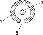
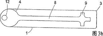
Fig. 3 a-3c shows the tubular exterior section 1 of device in further detail, and wherein Fig. 3 a is the view of looking from sidepiece, and Fig. 3 b is the view of looking from below, and Fig. 3 c is the view of looking from top.
Tubular exterior section 1 has vertical slit 8 along a part of length from the second end 4 beginnings, thereby allows the blood vessel of respective length to enter.
When exterior section 1 and interior section 2 were engaged, as shown in Figure 1, the second end 6 of tubular interior section 2 entirely or was partly surrounded by the part that disposes slit of exterior section 1.
Vertically the width of slit 8 equates with the double thickness of blood vessel wall basically.The effect of slit 8 is the vasculature parts that enter vertical slit 8 along the cross section restriction.Before entering vertical slit 8, this part blood vessel (referring to the process of Fig. 6) is by this way worn by being pricked, so that the blood vessel wall that the end 6 of interior section 2 is passed through in this part blood vessel when blood vessel enters in the slit 8.Afterwards, from the end 6 to the middle part 7 interior section 2 will be arranged in this part blood vessel that has entered slit 8.In this method, and by suppression (referring to the process of Fig. 6-8) in injection infusion needle 24 during bonding agent, along the new narrower solid passage of vascularization, thereby constituted from the end 6 of tubular interior section 2 to the living tissue passage of the end 4 of tubular exterior section 1.Fig. 4 a shows the outward appearance of new tunnel 401 when device A is applied on the blood vessel.For the purpose of clear, pulled down exterior section 1 in the accompanying drawings.Fig. 4 b shows the same position along cross sections.
After device A is applied in the blood vessel, two blood vessel wall are arranged in slit 8, the part circumference of blood vessel and partial-length (this length is consistent with the length of slit 8) are positioned at exterior section 1.The end 6 of tubular interior section 2 is by blood vessel wall, and this blood vessel wall is positioned at tubular exterior section 1.The width of slit 8 is enough to pass through for the nutrient of the blood vessel wall that is positioned at exterior section 1, but can not allow fluid to pass through, and promptly fluid can not be by between the compression blood vessel wall in the slit 8.Slit is too narrow will to prevent that nutrient from passing through, and will allow blood to pass through and form with foreign substance (end 6 of interior section 2) to contact but slit is too wide.
The end 4 of tubular exterior section 1 has at least one hole 12, thereby allows by suture blood vessel wall to be fixed on the exterior section 1.Partly by the opening 9-12 that fills up this exterior section 1, partly by in the inside that directly adheres to exterior section 1, this bonding agent also is fixed to blood vessel wall in the inside of exterior section 1, therefore by mechanical means blood vessel is fixed on the described exterior section 1.
Tubular exterior section 1 has via hole 11, and bonding agent is gone up and applied to (it is positioned at the place, end of the pipe 27 of guiding bonding agent) thereby handle assembly A is fixed to applicator.When the syringe holder bonding agent is expelled on the applicator, it is by hole 11 and fill up the inside of exterior section 1 and the space between the blood vessel wall.
Preferably, whole device A is by forming with solid material such as plastics, nylon, pottery or the metal of tissue compatible.Suitable plastic is polyether-ether-ketone (PEEK).Various piece can be by firm and can form by compatible different materials.If employed material can securely, stably carry out multiple disinfecting process as bearing 140 degree steam and air down, so as another disinfecting process, by heating and/or to resist down at 50 degrees centigrade that ethylene oxide,1,2-epoxyethanes carry out disinfection be favourable.
Fig. 5 a shows the applicator 20 of bringing device A with side view.Removing to patient under the hydrocephalic situation, when being applied to device A of the present invention on the blood vessel, especially when handle assembly A was applied to darker cervical region vein, applicator 20 helped this process.
The guiding bonding agent pipe 27 be arranged to securely, closely be connected in the hole 11 of this device at its lower end, but this device A still pulls down easily.The help of the power that is produced by infusion needle 24, handle assembly A remains on the correct position on the framework 21, and leads from described pin by hook-type guider 51 there.Described guider 51 advantageously is arranged to the less power on the described pin 24 is applied on the framework 21, helps device A is remained on power on the correct position of framework 21 thereby produced.The angled pin 58 that the upper end of pipe 27 is arranged through it is connected in the bonding agent syringe 26, and this pin 58 has a conduit and prevents to leak.
By lock 41 acupuncture treatment 23 is fixed on the framework 21.This lock comprises long, narrower part, and this part has hook 42 and two less protuberances 43,44, and each protuberance has the hole of acupuncture treatment of installing 23.This lock is arranged to acupuncture treatment 23 is remained on the tram and easily and pulls down.
When using applicator 20, silicon conduit 28 is connected on the end 5 of interior section 2 of this device A, thereby prevents leakage.This conduit 28 will be connected on the conduit of flow divider by adapter in the back of this process, allows the conduit of flow divider to be directly connected on the pipe joint of device A thereby perhaps be removed.
Lower part will be described device of the present invention and how be used to the conduit of guiding CSF is connected in people's the dark cervical region vein.
Device A and applicator 20 are symmetric, and their use is that the right hand is done or left hand is done irrelevant with the people who uses them.
Fig. 5 b shows the applicator of looking from sidepiece equally, and shows many cross sections.The framework that focuses on looking from the left side of the side view of accompanying drawing 5b of this accompanying drawing is at the cross section of position AA to D and G.The docking location 54 of the framework 21 of device A has been shown in cross section AA.How pipe 27 extends in the docking location 54 if being shown in cross section B.How hook-type guider 51 is arranged to lead for like that as mentioned above infusion needle 24 if being shown in C.Guide openings 56 has been shown in D.View E and F show from two views, look perpendicular to side view, promptly from behind and above the locking wheel of (two) syringe of looking.The cross section of framework at position G place has been shown in G, and this cross section has the profile of similar inverted T-shaped.
Fig. 6 shows the first of application process.Dark cervical region venous appropriate length is undertaken freely dissecting, promoting by supporting construction 31 and is fixing.Along being parallel to blood flow or the reverse direction application apparatus A that is parallel to blood flow.Double slit line 33 is placed on nearside and distal side with respect to the position that will prick.Help pricking the hole by using suture needle to promote the venous blood vessel wall.After pricking the hole, pull down acupuncture treatment 23.
How Fig. 7 shows by make suture extend through opening 9 along the direction relative with infusion needle 24 by slit 8 and makes the infusion needle 24 with device A further enter into vein.In this method, the inside tube 2 of device A is more prone to by the venous blood vessel wall.
The correct position of vein in device A can be checked with three kinds of methods:
A. in upper opening 10, can observe the venous blood vessel wall.
B. make suture clearly relative with upper opening 10.
C. slit 8 should fill up blood vessel wall in its gamut.
Fig. 8 show double slit line 33 tie up in pipe around and also tie up to around the outer pipe by extra sewing up the incision.Fig. 8 also shows suture 32, and this suture 32 is connected to the wall of duct of Arantius on the device A of 12 vicinity, hole.
When wall of vein is on the correct position of device A and is fixed with suture, firmly inject bonding agent.The bonding agent of syringe 26 is the hole 11 in the exterior section of injection by this device by pipe 27 and by this way, so that the inside of exterior section and the space between the blood vessel wall and all openings have filled up bonding agent.Infusion needle plays the mould effect of new tunnel, and this new tunnel can obtain the length identical with slit 8.
Fig. 9 shows the 4th part of this process.
When bonding agent was solidified after a few minutes, the bonding agent syringe is removed and infusion needle is withdrawn into such position: on this position, pin ended at the inside of the interior section 2 of device A.Now, make preserved material from new tunnel, clean out blood, and can check its function by infusion needle.Afterwards, infusion needle is withdrawn fully, and device A discharges from applicator 20 and can be connected on the conduit from flow divider.
After as much as possible extra bonding agent being joined the outside of this device, thereby wound is sewn and makes device A produce extra support.
By means of device A of the present invention, now the darker cervical region vein of a part is become variable volume, narrower solid passage.The wall of this passage is the wall of vein alive with better nutrition, and this passage has filled up CSF.By tightness in blocky blood vessel wall, the slit and flow divider, prevent that blood from refluxing in this passage.New tunnel is had to narrower (diameter is approximately 1 millimeter) thereby blood motion is in vein for permission CSF (per 24 hours less than 500 milliliters) in a small amount, and this blood is mixed with CSF at opening part.
Correspondingly, the present invention can be discharged to CSF in the darker cervical region vein and further be discharged in the heart, and can between the blood flow in the fluidic conduit of guiding or any foreign substance and the vein, not form contact, avoid using X ray, EGG or other device to guarantee the correct position of conduit in heart simultaneously.
The present invention does not also have the dangerous of thrombosis and has reduced the danger of infecting because device of the present invention, the fluidic conduit of guiding or any other foreign substance not with vein in blood flow produce and contact.Be discharged to the anti-siphonage that has produced nature in the darker cervical region vein.
Figure 10 a shows and is used for supporting, fixes and close the support of blood vessel or the view of bracing or strutting arrangement 1000.When being connected to the hydrocephalus diverter of the embodiment of the invention on the vein, bracing or strutting arrangement 1000 is particularly conducive to and supports and fixing cervical region vein, and the above-mentioned supporting construction 31 among Fig. 6 advantageously equals this bracing or strutting arrangement 1000.
The embodiment of this support comprises common ground 1004, branch point 1005 and two elongate articles of handle 1001, sweep 1003, extension, an elongate articles is a spill or U-shaped 1010,1012,1015, and another elongate articles is L shaped 1020,1025.It is flat part basically that this support preferred design has, and promptly design has common ground 1004 at least, and the not end parts 1015 of U-shaped spare 1010,1012,1015 to be arranged to have be orthogonal cross section basically, its thickness is basically less than corresponding width.In typical embodiment, this thickness is approximately 0.5-2.5mm, and the width of common ground is approximately 5-15mm.
This support is provided with the blood vessel that comes between U-shaped spare 1015 and L shaped 1025 and captures in the opening 1030, and this opening 1030 is formed between described; Described opening 1030 extends into slit 1031 longitudinally between described 1012,1025.The width of the described vertical slit 1031 between these parts equates that with the double thickness of the blood vessel wall of above-mentioned blood vessel promptly some embodiment of bracing or strutting arrangement provide the slit of different size size basically, and the device of different size size itself can certainly be provided.Reason with slit of the sort of size is that when vascular clamp was in slit, blood vessel was flattened and is compressed, and has therefore reduced blood flow.Typical width comprises 1-1.5mm.In most cases, this minimizing can make blood flow be cut off fully.U-shaped spare and L shaped preferably have rectangle or square cross section, thereby and so arrange so that be formed at described opening 1030 between part 1012 and 1025 and slit enough wide when this support is reversed a little the permission vascular slide on the correct position lightly.Therefore these parts have circular edge, reduce or eliminated the danger of during rationally using bracing or strutting arrangement injury vascular or other tissue.Opening 1030 is preferably so arranged, so that the free end 1026 of part 1025 is arranged to relative with the not sweep between the end parts 1014 of U-shaped spare 1012,1015.Described free end 1026 forms trianglees, so opening 1030 is beginning to locate broad and narrower when it carries out the transition to slit 1031.
When the not end parts of U-shaped spare and common sparing 1004 or and then the part U-shaped spare of branch point 1005 when L shaped 1010,1020 is arranged to contact edge of wound, and because the cross section of described part and part is flat or rectangle, this support is designed at the surgical wound place it is locked on the correct position itself.When vascular is sandwiched in the slit between the part 1025,1012 or just leans against these two above the part time, because vascular itself acts on certain force on the bracing or strutting arrangement 1000, this bracing or strutting arrangement 1000 points to the bottom of surgical wound down, so this device can enter on the correct position smoothly.
Claims (12)
1. a device (A), this device fluid from guiding fluidic catheter guidance to blood vessel, it is characterized in that, this device has formed passage with blood vessel on the partial-length of blood vessel, this passage is arranged essentially parallel to blood vessel ground and extends, and device (A) does not contact with endovascular blood flow with the fluidic conduit of guiding, and described device (A) comprising: be tubular exterior section (1) basically, this exterior section (1) has first end (3) and the second end (4); And be tubular interior section (2) basically, it has first end (5) and the second end (6), it is parallel axis basically that described exterior section is furnished with interior section, and externally the first end (3) of part (1) is located or is located to be bonded with each other near this first end and at the mid portion (7) of interior section (2), extend from the second end (4) of exterior section (1), a part of length along exterior section (1) is provided with the vertical slit (8) that is used for laying a part of blood vessel, the first end (5) of interior section (2) is arranged to be connected on the conduit, and the second end (6) of interior section (2) entirely or is partly surrounded and be arranged through wall of vein by described exterior section (1).
2. device as claimed in claim 1 is characterized in that, vertically slit (8) has such width, and this width equates with the double thickness that this device is used for the blood vessel wall of blood vessel wherein basically.
3. device as claimed in claim 1 or 2 is characterized in that, exterior section (1) and interior section (2) engage by screw thread.
4. device as claimed in claim 1 or 2 is characterized in that, exterior section (1) and interior section (2) engage by tapered contact surface.
5. device as claimed in claim 1 or 2 is characterized in that, exterior section (1) and interior section (2) form one.
6. device as claimed in claim 1 or 2 is characterized in that, by this way with the second end (4) of angle cutting exterior section (1) so that exterior section (1) to have that side of vertical slit (8) the shortest.
7. device as claimed in claim 1 or 2, it is characterized in that, exterior section (1) is provided with first opening (9) and second opening (10) near first end (3), wherein first opening (9) engages with vertical slit (8) and perpendicular to groove (8), and that second opening (10) is arranged to along diametric(al) is relative with first opening (9) basically.
8. device as claimed in claim 1 or 2 is characterized in that, exterior section (1) locates to be provided with at least one hole (12) at its second end (4), thereby this device is sewn in the blood vessel.
9. device as claimed in claim 1 or 2 is characterized in that, exterior section (1) is provided with porose (11) and is used for adding bonding agent and/or is used for temporary transient handle assembly and be fixed to applicator device.
10. device as claimed in claim 1 or 2 is characterized in that, this device is formed by the solid material with tissue compatible.
11. device as claimed in claim 10 is characterized in that, described and solid material tissue compatible is a polyether-ether-ketone.
12. an applicator, it is applied ointment or plaster the arbitrary described device of claim 1-11 in blood vessel, it is characterized in that, applicator (20) comprising: frame part (21), and it is arranged and keeps infusion needle (24); Acupuncture treatment (23), it is connected on the applicator (20) by lock portion (41) and pipe (25); And the pipe (27) of guiding bonding agent, it is connected on the bonding agent syringe (26).
Applications Claiming Priority (2)
| Application Number | Priority Date | Filing Date | Title |
|---|---|---|---|
| NO20005469A NO20005469L (en) | 2000-10-30 | 2000-10-30 | Device for conducting fluid from a catheter to a blood vessel |
| NO20005469 | 2000-10-30 |
Publications (2)
| Publication Number | Publication Date |
|---|---|
| CN1471416A CN1471416A (en) | 2004-01-28 |
| CN1299780C true CN1299780C (en) | 2007-02-14 |
Family
ID=19911734
Family Applications (1)
| Application Number | Title | Priority Date | Filing Date |
|---|---|---|---|
| CNB018181945A Expired - Fee Related CN1299780C (en) | 2000-10-30 | 2001-10-26 | System and method for physiologial drainage |
Country Status (13)
| Country | Link |
|---|---|
| US (1) | US7476211B2 (en) |
| EP (1) | EP1335770B1 (en) |
| JP (1) | JP2004512149A (en) |
| CN (1) | CN1299780C (en) |
| AT (1) | ATE296659T1 (en) |
| AU (2) | AU2002212884B2 (en) |
| BR (1) | BR0115038A (en) |
| CA (1) | CA2426910A1 (en) |
| DE (1) | DE60111255T2 (en) |
| ES (1) | ES2242779T3 (en) |
| NO (1) | NO20005469L (en) |
| RU (1) | RU2278696C9 (en) |
| WO (1) | WO2002036193A1 (en) |
Families Citing this family (13)
| Publication number | Priority date | Publication date | Assignee | Title |
|---|---|---|---|---|
| ATE399577T1 (en) | 2000-09-11 | 2008-07-15 | Csf Dynamics As | FLUID DRAIN DEVICE FOR TREATING HYDROCEPHALUS |
| US20050163821A1 (en) * | 2002-08-02 | 2005-07-28 | Hsing-Wen Sung | Drug-eluting Biodegradable Stent and Delivery Means |
| JP4370230B2 (en) * | 2004-09-08 | 2009-11-25 | 株式会社カネカメディックス | Medical tubing and shunt system |
| DE102008030942A1 (en) | 2008-07-02 | 2010-01-07 | Christoph Miethke Gmbh & Co Kg | Cerebrospinal fluid drainage |
| US20100191168A1 (en) | 2009-01-29 | 2010-07-29 | Trustees Of Tufts College | Endovascular cerebrospinal fluid shunt |
| JP4846044B1 (en) * | 2010-06-30 | 2011-12-28 | テルモ株式会社 | Medical device |
| US9737696B2 (en) | 2014-01-15 | 2017-08-22 | Tufts Medical Center, Inc. | Endovascular cerebrospinal fluid shunt |
| WO2015108917A1 (en) | 2014-01-15 | 2015-07-23 | Tufts Medical Center, Inc. | Endovascular cerebrospinal fluid shunt |
| US20160136398A1 (en) | 2014-10-31 | 2016-05-19 | Cerevasc, Llc | Methods and systems for treating hydrocephalus |
| EP3368137B1 (en) | 2015-10-30 | 2021-03-03 | CereVasc, Inc. | Systems for treating hydrocephalus |
| EP3762083A1 (en) | 2018-03-08 | 2021-01-13 | CereVasc, Inc. | Systems and methods for minimally invasive drug delivery to a subarachnoid space |
| RU2714394C1 (en) * | 2019-04-02 | 2020-02-14 | Евгений Александрович Головин | Connector for retrograde arterial pressure measurement in internal carotid artery |
| CN117282004B (en) * | 2023-11-24 | 2024-01-26 | 通桥医疗科技有限公司 | Shunt for treating hydrocephalus and system thereof |
Citations (6)
| Publication number | Priority date | Publication date | Assignee | Title |
|---|---|---|---|---|
| US3738365A (en) * | 1969-07-22 | 1973-06-12 | R Schulte | Spring reinforced extensible catheter |
| US3769982A (en) * | 1971-09-24 | 1973-11-06 | R Schulte | Physiological drainage system with closure means responsive to downstream suction |
| US3894541A (en) * | 1974-02-27 | 1975-07-15 | El Shafei Ismail Lotfy | Method of treating hydrocephalus |
| CN2149917Y (en) * | 1993-02-15 | 1993-12-22 | 郑州市第五人民医院 | Needle-guiding device for puncture through vagina |
| CN1081622A (en) * | 1992-04-24 | 1994-02-09 | 洛马林达大学医学中心 | Can guarantee the cerebrospinal fluid bypass that the bottom line operation is revised |
| CN2291897Y (en) * | 1997-03-11 | 1998-09-23 | 李森恺 | Puncture fistulation leading device |
Family Cites Families (16)
| Publication number | Priority date | Publication date | Assignee | Title |
|---|---|---|---|---|
| US465574A (en) * | 1891-12-22 | Separating-machine | ||
| US520768A (en) * | 1894-06-05 | baxter | ||
| US476400A (en) * | 1892-06-07 | morgan | ||
| US463105A (en) * | 1891-11-10 | Pipe-cutter | ||
| US3877429A (en) * | 1973-11-30 | 1975-04-15 | David L Rasumoff | Catheter placement device |
| US4122858A (en) | 1977-03-23 | 1978-10-31 | Peter Schiff | Adapter for intra-aortic balloons and the like |
| JPS5421089A (en) | 1977-07-16 | 1979-02-16 | Kawasumi Lab Inc | Stabilizer for sampling and transfusing blood |
| US4631051A (en) | 1984-09-24 | 1986-12-23 | Cordis Corporation | Ventricular amniotic shunt and introducer system |
| US4655745A (en) | 1985-07-29 | 1987-04-07 | Corbett Joseph E | Ventricular catheter |
| US4767400A (en) | 1987-10-27 | 1988-08-30 | Cordis Corporation | Porous ventricular catheter |
| US5207684A (en) | 1992-04-13 | 1993-05-04 | Neuro Navigational Corporation | Sheath for shunt placement for hydrocephalus |
| US5618270A (en) | 1995-05-26 | 1997-04-08 | Orejola; Wilmo C. | Transthoracic aortic sleeve |
| JP3345317B2 (en) * | 1997-10-09 | 2002-11-18 | 旭光学工業株式会社 | Endoscope injection tool |
| JP4115587B2 (en) | 1998-05-19 | 2008-07-09 | 株式会社トップ | Wing needle protector |
| US6045547A (en) * | 1998-06-15 | 2000-04-04 | Scimed Life Systems, Inc. | Semi-continuous co-extruded catheter shaft |
| US6193691B1 (en) | 1999-03-30 | 2001-02-27 | Depuy Orthopaedics, Inc. | Catheter system |
-
2000
- 2000-10-30 NO NO20005469A patent/NO20005469L/en not_active Application Discontinuation
-
2001
- 2001-10-26 BR BR0115038-3A patent/BR0115038A/en not_active IP Right Cessation
- 2001-10-26 CN CNB018181945A patent/CN1299780C/en not_active Expired - Fee Related
- 2001-10-26 US US10/415,397 patent/US7476211B2/en not_active Expired - Fee Related
- 2001-10-26 EP EP01981227A patent/EP1335770B1/en not_active Expired - Lifetime
- 2001-10-26 AU AU2002212884A patent/AU2002212884B2/en not_active Ceased
- 2001-10-26 RU RU2003115609/14A patent/RU2278696C9/en not_active IP Right Cessation
- 2001-10-26 WO PCT/SE2001/002362 patent/WO2002036193A1/en active IP Right Grant
- 2001-10-26 AU AU1288402A patent/AU1288402A/en active Pending
- 2001-10-26 JP JP2002539002A patent/JP2004512149A/en active Pending
- 2001-10-26 ES ES01981227T patent/ES2242779T3/en not_active Expired - Lifetime
- 2001-10-26 DE DE60111255T patent/DE60111255T2/en not_active Expired - Fee Related
- 2001-10-26 AT AT01981227T patent/ATE296659T1/en not_active IP Right Cessation
- 2001-10-26 CA CA002426910A patent/CA2426910A1/en not_active Abandoned
Patent Citations (6)
| Publication number | Priority date | Publication date | Assignee | Title |
|---|---|---|---|---|
| US3738365A (en) * | 1969-07-22 | 1973-06-12 | R Schulte | Spring reinforced extensible catheter |
| US3769982A (en) * | 1971-09-24 | 1973-11-06 | R Schulte | Physiological drainage system with closure means responsive to downstream suction |
| US3894541A (en) * | 1974-02-27 | 1975-07-15 | El Shafei Ismail Lotfy | Method of treating hydrocephalus |
| CN1081622A (en) * | 1992-04-24 | 1994-02-09 | 洛马林达大学医学中心 | Can guarantee the cerebrospinal fluid bypass that the bottom line operation is revised |
| CN2149917Y (en) * | 1993-02-15 | 1993-12-22 | 郑州市第五人民医院 | Needle-guiding device for puncture through vagina |
| CN2291897Y (en) * | 1997-03-11 | 1998-09-23 | 李森恺 | Puncture fistulation leading device |
Also Published As
| Publication number | Publication date |
|---|---|
| BR0115038A (en) | 2004-02-03 |
| WO2002036193A1 (en) | 2002-05-10 |
| US20040087887A1 (en) | 2004-05-06 |
| CA2426910A1 (en) | 2002-05-10 |
| JP2004512149A (en) | 2004-04-22 |
| CN1471416A (en) | 2004-01-28 |
| EP1335770A1 (en) | 2003-08-20 |
| US7476211B2 (en) | 2009-01-13 |
| EP1335770B1 (en) | 2005-06-01 |
| AU1288402A (en) | 2002-05-15 |
| RU2278696C9 (en) | 2007-01-27 |
| ES2242779T3 (en) | 2005-11-16 |
| NO20005469D0 (en) | 2000-10-30 |
| RU2278696C2 (en) | 2006-06-27 |
| DE60111255D1 (en) | 2005-07-07 |
| NO20005469L (en) | 2002-05-02 |
| DE60111255T2 (en) | 2006-05-04 |
| ATE296659T1 (en) | 2005-06-15 |
| AU2002212884B2 (en) | 2006-06-29 |
Similar Documents
| Publication | Publication Date | Title |
|---|---|---|
| CN1299780C (en) | System and method for physiologial drainage | |
| US8920390B2 (en) | Vascular access port with tubular shaped septum | |
| US8343138B2 (en) | Subdural evacuation port aspiration device | |
| US10434296B2 (en) | Intraosseous infusion ports and methods of use | |
| CN108472019A (en) | Method and apparatus for treating apoplexy | |
| US20140364821A1 (en) | System and method for draining fluids | |
| KR101103372B1 (en) | Apparatus for fixing catheter comprising vertical fixing element | |
| US20070173754A1 (en) | Extravasation minimization device | |
| CN106039527B (en) | High-flow anti-blocking flushable drainage catheter for orthopedics department | |
| AU2002212884A1 (en) | System and method for physiological drainage | |
| KR102311674B1 (en) | Catheter device for reducing the pain after surgery | |
| CN214595959U (en) | Adjustable intravascular flushing device for operation | |
| CN208389156U (en) | A kind of tumour one-step method puncture drainage hardening external member | |
| CN217219861U (en) | Epidural flushing drainage tube for treating spinal cord injury or infection | |
| CN215194122U (en) | Suction device | |
| CN1158973C (en) | Drain for intracranial puncture | |
| WO2023181979A1 (en) | Therapeutic device for brain diseases, connector for therapeutic devices, and connector fixing tool for therapeutic devices | |
| CN114642822A (en) | Epidural irrigation drainage tube for treating spinal cord injury or infection and using method thereof | |
| CN215023183U (en) | Novel closed negative pressure double-cavity drainage system | |
| KR20230161184A (en) | A chest catheter for insertion into the pleural cavity | |
| CN211188710U (en) | Novel surgical drainage tube | |
| CN115554482A (en) | Catheter drainage component for medicine or food poisoning | |
| CN102526818B (en) | Drainage package for minimally invasive intracranial hematoma removal surgery |
Legal Events
| Date | Code | Title | Description |
|---|---|---|---|
| C06 | Publication | ||
| PB01 | Publication | ||
| C10 | Entry into substantive examination | ||
| SE01 | Entry into force of request for substantive examination | ||
| C14 | Grant of patent or utility model | ||
| GR01 | Patent grant | ||
| C17 | Cessation of patent right | ||
| CF01 | Termination of patent right due to non-payment of annual fee |
Granted publication date: 20070214 Termination date: 20091126 |