CN1290468A - Sonic emitter with foam stator - Google Patents
Sonic emitter with foam stator Download PDFInfo
- Publication number
- CN1290468A CN1290468A CN99802767A CN99802767A CN1290468A CN 1290468 A CN1290468 A CN 1290468A CN 99802767 A CN99802767 A CN 99802767A CN 99802767 A CN99802767 A CN 99802767A CN 1290468 A CN1290468 A CN 1290468A
- Authority
- CN
- China
- Prior art keywords
- film
- foam components
- variable voltage
- equipment according
- areola
- Prior art date
- Legal status (The legal status is an assumption and is not a legal conclusion. Google has not performed a legal analysis and makes no representation as to the accuracy of the status listed.)
- Pending
Links
Images


Classifications
-
- H—ELECTRICITY
- H04—ELECTRIC COMMUNICATION TECHNIQUE
- H04R—LOUDSPEAKERS, MICROPHONES, GRAMOPHONE PICK-UPS OR LIKE ACOUSTIC ELECTROMECHANICAL TRANSDUCERS; DEAF-AID SETS; PUBLIC ADDRESS SYSTEMS
- H04R3/00—Circuits for transducers, loudspeakers or microphones
-
- H—ELECTRICITY
- H04—ELECTRIC COMMUNICATION TECHNIQUE
- H04R—LOUDSPEAKERS, MICROPHONES, GRAMOPHONE PICK-UPS OR LIKE ACOUSTIC ELECTROMECHANICAL TRANSDUCERS; DEAF-AID SETS; PUBLIC ADDRESS SYSTEMS
- H04R19/00—Electrostatic transducers
Landscapes
- Physics & Mathematics (AREA)
- Engineering & Computer Science (AREA)
- Acoustics & Sound (AREA)
- Signal Processing (AREA)
- Electrostatic, Electromagnetic, Magneto- Strictive, And Variable-Resistance Transducers (AREA)
- Transducers For Ultrasonic Waves (AREA)
- Circuit For Audible Band Transducer (AREA)
Abstract
A speaker device comprising an electrostatic emitter film (15) which is responsive to an applied variable voltage (13) to emit sonic output (11) based on a desired sonic signal, used in combination with at least a first foam member (20) having a forward face (21), an intermediate core section (22) and a rear face (23). The forward face (21) is composed of a composition having sufficient stiffness to support the electrostatic film (15) and includes conductive properties which enable application of a variable voltage to supply the desired sonic signal. The surface of the forward face (21) includes small cavities (26) having surrounding wall structure defining each cavity which terminates at contacting edges (27) approximately coincident with the forward face of the foam member. The film is applied to the forward face of the foam member and biased in direct contact with the contacting edges of the forward face.
Description
The present invention relates to capacitive character or static pinger, relate in particular to such reflector: comprise that stator parts and the response as loudspeaker apparatus that is associated add the movable reflector film that variable voltage produces sound wave output.
For a long time, using related movable static diaphragm that also insulate with stator or driver part or film is known in acoustics as the part of loud speaker and/or microphone equipment.The typical construction of this equipment comprises flexible polyester film (tm) with metal coating or Kapton (tm) film and the conductive rigid plate that is separated by air gap or insulating material that is associated.The applied voltage that comprises acoustic signals is transported to this capacitive component, makes flexible reflector film displacement to propagate the sound compressional wave of expectation.
There are the main electrostatic loudspeaker of two classes in application and frequency according to sound wave output.Single ended speaker comprises single plate, has the hole that allows sound to pass through usually.Film is suspended in the front or the back of plate, can it not contacted with plate by pad.For ultrasonic transmitter, the film deflection directly contacts with irregular plate face, thereby film can vibrate in bag or chamber.The insulation barrier of air, plastic film or similar non-conducting material is clipped between film and the plate, to prevent electric contact and electric arc.Typically, plate is connected with DC power supply with diaphragm, at the relative conductive surface generation opposite polarity of metal coating and plate.The capacitive relationship of being brought by this structure can make electrostatic loudspeaker convert variable voltage to compressional wave such sound wave output.
The main electrostatic loudspeaker of second class is representative with the push-pull configuration.In this case, loud speaker has two rigid plate, and they are placed on the both sides of conductive film symmetrically.Because applied voltage, a plate is negative with respect to diaphragm, and another plate is assumed to positive charge.The variable voltage that is transported to this capacitive component has been strengthened the effect of recommending to diaphragm, thereby has increased power output.The theory of general static emitter design and the further details of structure are seen: ElectrostaticLoudspeaker, Ronald Wagner, Audio Amateur publishing house, 1993.
Decision-orientated study is for many years developed various technological improvements to this fundamental system, but the element definition does not become always.Especially, be generally film as the rigid plate of stator or stationary parts supporting is provided, and provide conducting medium for the application of the acoustic signals of expectation.The typical material that is used for plate structure comprises aluminium, copper planar circuit board and similar material as known in the art.
Although this pattern that material is selected is mainly served the needed purpose of electrostatic loudspeaker, lack alternative composition and limited the variation in the loudspeaker applications.For example, the voice system general size is very big, so that the exploitation of compatible lower frequency.Therefore, weight and physical dimension have become important design factor.And, cause plate member to be configured to the load bearing component of speaker system usually to the rigidity of acceptable panel material and the requirement of known hardness.Simultaneously, the conventional limited accepted of plate developing history has shifted the attentiveness of people to other options in the design of exploitation electrostatic loudspeaker.
An object of the present invention is to common electrostatic loudspeaker structure provides interchangeable assembly material, thisly be configured in structure and the acoustic characteristic aspect provides new variation.
Another object of the present invention is by reducing weight and hardness requirement with foamed material as the stator parts of speaker system.
A further object of the present invention is various plates of exploitation or stator composition, the selectance that these compositions provide sound to transmit based on the ON/OFF cell structure.
A further object of the present invention provide a kind of in the gamut that comprises the output of audio frequency and superaudible sound wave with the plate or the support unit of single or push-pull configuration work.
Another object of the present invention provides a kind of foam stator or plate of cheapness, and they are in light weight and can form various geometries, not only economy but also strengthened performance.
Specific purposes of the present invention provide a kind of electrostatic loudspeaker that is used for audio applications, and it has fully reduced manufacturing cost, has simplified design.
These and other purpose of the present invention realizes by a kind of loudspeaker apparatus.Described loudspeaker apparatus comprises: the static reflector film and first foam components, and static reflector film in response adds variable voltage, and according to the acoustic signals emission sound wave output of expectation, first foam components has front, intermediate core part and back.The front is grouped into by the one-tenth that hardness is enough to support electrostatic film and have conductive characteristic, and conductive characteristic can provide the acoustic signals of expectation with variable voltage.The surface of front comprises areola, and cavity has the leg structure that limits each cavity, and each cavity terminates on the engagement edge that roughly overlaps with the front of foam components.Film is added to the front of foam components, is directly contacted with the engagement edge of front by deflection, makes the direct tread support membrane in front.Signal source connects loudspeaker apparatus, is used to provide the variable voltage that comprises acoustic signals.The present invention also disposes first front as insulating element, intermediate core and/or can be used as the back of conductive component.
In another embodiment of the present invention, develop push-pull configuration, utilized second foam components of the similar structures that is positioned at the first foam components offside on the static reflector film.Static reflector film is clipped between the corresponding thin film component, comprises the conductive layer that becomes the noncontact relation with corresponding first and second foam components, so that make first and second fronts of film capacitively respond variable voltage with push-pull relationship.
Another distortion of the present invention comprises: static reflector film, can in audio range, work, support unit with band front, intermediate core and back, wherein the front is grouped into by the one-tenth that hardness is enough to support electrostatic film and comprise conductive characteristic, and conductive characteristic can provide the sound signal of expectation with variable voltage.Electrostatic film is applied to the front of support unit and is directly contacted with engagement edge by deflection.Moreover system can adapt to symmetrical operation with second support unit, also can make amendment so that insulating barrier exchange mutually in front to system.
An alternative embodiment of the invention comprises the static reflector film and first foam components, and static reflector film in response adds the output of variable voltage emission sound wave, and first foam components has front, intermediate core part and back.Moreover foam components is grouped into by the one-tenth that comprises conductive characteristic, and conductive characteristic can be used variable voltage will expect that acoustic signals offers the reflector film from foam components.The front comprises areola, and areola has the leg structure that limits each cavity, and wherein the leg structure is roughly stopping with the place of coincidence, front of foam components.The film supports device is provided, is used in the scope of the electromotive force that in foam components, forms by variable voltage the electrostatic film of location and dislocation foam components front at a certain distance.By realizing symmetrical operation on the offside that second foam components is added to film along comparable orientation.
The present invention also comprises a kind of method of conduct acoustic waves energy, may further comprise the steps: a) select foam components, described foam components to have and variable voltage can be added to the front areola of front with the leg structure qualification of conductive characteristic that the expectation acoustic signals is provided by comprising; B) static reflector film is applied to the front of foam components, static reflector film in response applied voltage is according to the acoustic signals emission sound wave output of expectation; C) make film with respect to the front deflection, make film respond the variable voltage of foam components as the static reflector; D) variable voltage is offered foam components and transmitter combinations; And e) the audio compression ripple propagates into the surrounding air from reflector.
Of the present invention these and other purpose and feature will be in conjunction with the drawings to the description of embodiments of the invention and further specified.In these accompanying drawings:
Fig. 1 is the side cross-sectional view of single-ended electrostatic loudspeaker constructed according to the invention.
The partial cross section figure that Fig. 2 cuts open along the line 2-2 of Fig. 1.
Fig. 3 shows the face upwarding view of part foam stator, has wherein separated cavity and feature for ease of explanation.
Fig. 4 shows a kind of possible shape of this loudspeaker apparatus-arc.
Fig. 5 shows a kind of possible shape of this loudspeaker apparatus-cylindrical.
Fig. 6 provides the schematic diagram of a kind of citation form of this loudspeaker apparatus in push-pull configuration.
Fig. 7 shows an alternative embodiment of the invention, and wherein thin film component is clipped between the relative foam stator.
Fig. 8 shows an alternative embodiment of the invention with single-film parts.
Fig. 9 shows and comprises another embodiment that expands net form metal stator.
Figure 10 is another cylindrical embodiment of the present invention.
Figure 11 shows the diagonal cross section of another embodiment of Figure 10, cuts open along cylindrical central shaft.
Figure 12 and 13 shows many films embodiment of the present invention.
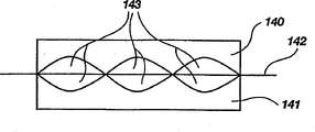
Figure 14,15 and 16 shows that to be suitable for another kind of the present invention arc.
By disclosed most preferred embodiment hereinafter the some creative notion that proposes in the subsidiary claim is described.It will be appreciated by those skilled in the art that, have a lot of distortion, the accompanying drawing that this paper provided is in order to make those of ordinary skill in the art can use these creative notions in other equipment of multiple different loadspeaker structures and conduct acoustic waves energy with example.Thereby following description not conduct limits, but limits scope of the present invention by the accompanying Claim book.
For example, Fig. 1 and 2 shows the single ended speaker equipment 10 with sound wave output 11, and sound wave output 11 is propagated with forward 12.This loud speaker can be connected to audio amplifier or ultrasonic drive 13, and amplifier or driver 13 provide various electronic circuit support units to be suitable for the acoustic signals of expectation.This circuit is well-known, is not described in detail at this.13 many signal sources of representative of amplifier or driver comprise traditional radio, TV, recording or other audio systems.
Equipment comprises static reflector film 15, and 15 responses of static reflector film add variable voltage, according to the acoustic signals emission sound wave output of expectation.As shown in Figure 2, the reflector film comprises plastic sheet 16 and thin metal coating 17 or other conductive surfaces.Static amplifier film also is well-known, has been applied in a lot of capacitive characters or the layering Charge System, and they are referred to as electrostatic apparatus hereinafter.Typically, plastic sheet is polyester film (tm), Kapton (tm) or other non-conductive compositions, and these compositions can serve as the insulator between thin metal layer 17 and the stator parts 20.Having the surface of local conductivity or coating can be used for crossing membrane surface and forms uniform CHARGE DISTRIBUTION.Preferred resistance coefficient scope is greater than 10k ohm.This provides charge migration still less and has prevented to produce the static that causes electric arc.Higher impedance for example 100 megaohms is very common in this application.Obviously, this selection also influences two electric capacity between the plate.
The characteristic of reflector film comprises flexible, suitable resistance coefficient and tensile strength, and all these all develop finely in existing electrostatic loudspeaker technology.By means of the present invention, the reflector film combinations of having used in prior art systems may provide the operability of certain level in new application of the present invention.In certain embodiments, importantly reflector can meet the bag shape surface of foam, thereby can be in the different part of each cavity isolation.This is not that suggestion reflector vibration is limited in the space of just being caught by each cavity, and still, reason is that the edge effect between the cavity and the vibration that intersects can illustrate the unexpected effect of this combination as audio tweeter.
One of principal character of the present invention comprises with foam components as stator 20.With respect to light, flexible reflector film 15, stator serves as basic components or the rigid element that inertia is provided.This stator is to conducting element, for capacitor bank provides a polarity.The resistance coefficient of these parts is chosen to facilitate uniform charge migration, to avoid other intrinsic in electric arc and electrostatic system negative effects.Optimal components with available characteristic of confirmation is the conventional electrostatic packing foam (being commonly referred to " conductive foam ") as the packaging material of computer and other charge sensitive objects.This material is used for providing static discharge to allergen.It not only guard block be not subjected to the influence of disadvantageous electrical discharge or exposure, and weight very gently, not expensive.In fact it be formed in the equipment of regular-type foam moulding with Any shape, density or size usually.
In the prior art, the use of material generally is limited in passive position (packaging material), and its purpose only is the protection sensing unit.As other packaging material, effect is based on interim placement to fill the space in carton box or the case.Usually, this material is not lost with case because there being independent value.Its existence in the electronic market is considered to certain always, and is proved by a large amount of rubbish in the whole world.
The inventor has found unusual and unexpected property combination, and these characteristics provide the effective performance as stator parts in the electrostatic loudspeaker systems jointly.The advantage of this material becomes more obvious by explanation; So far, this cheap material is can save cost and more near public market as the potential of the electrostatic loudspeaker systems of complex and expensive but obviously.As everybody knows, the prior art electrostatic loudspeaker systems is very responsive to motion, volume is big, heavy and usually than homotype technology of acoustic wave costliness.Advantageously influence above-mentioned each factor with light-duty " packing " foam as the critical piece of loud speaker, thereby opened the new situation that the electrostatic loudspeaker technology is used.
Accompanying drawing shows at random the foaming composition of bag or cavity.Can also make the void size in the plastic matrix more even with available techniques.Therefore, can adjust and optimize the stator parts for concrete frequency application, resonance and correlation properties.The hardness of foam or rigidity are material behavior and bag density and limit each space or the function of the wall thickness of bag.Therefore, control at random-the uniform gap size outside, can further control the stator acoustic response by changing various physical parameters.The importance of rigidity is well-known in the stator parts, at present can be by coming the part to be influenced with the unique relevant new design factor of foaming composition.
Just for purpose is discussed, foam components 20 is divided into three parts in theory.Although physically can construct multilayer foams and part, this demonstration is equally applicable to uniform single component.Specifically, foam stator parts comprise front 21, intermediate core part 22 and back 23.With tangible method for a person skilled in the art, can finish hereinafter described various functions by one or more in these parts.
For example, any one the some or all part in these parts can be grouped into by the one-tenth that hardness is enough to support as the electrostatic film of the part of speaker system.And any one part in these parts or a plurality of part can comprise the conductive characteristic that can drive reflector diaphragm or film with variable voltage.Fig. 1 shows and uses the single component with required hardness and conductivity; But according to the needs of special speaker system, these characteristics may be limited to the front too.Similarly, in the middle of conductive characteristic may be limited to and/or back is among the described especially hereinafter embodiment of front as insulator.
Refer again to accompanying drawing, specifically with reference to figure 3, front 21 comprises surface 25, and surface 25 comprises areola 26, and areola 26 has the leg structure 27 that limits each cavity.The leg structure terminates on the engagement edge that roughly overlaps with the front of foam components.Here, these features 25,26 and 27 size and the profile systematic function optimum that can be chosen to make expectation.In the place that needs uniform properties, can use mould accurately to form the front structure of expectation.
By film laminating device 30 for example framework, anchor clamps or carriage in conjunction with reflector film and stator, so that electrostatic film is applied on the front of foam components.In this embodiment of Fig. 1, film directly contacts with the front.Therefore, conductive component is foam and metal coating, and plastic film provides appropriate insulation betwixt.Perhaps make the film deflection directly contact the engagement edge of front, thereby film is directly by preceding surface bearing with deflection device.The voltage that can add by 13 pairs of these deflection device of circuit perhaps by independent source, comprises mechanical device.Provide lead 32 or other jockeys that signal source 13 is connected to loudspeaker apparatus, so that the variable voltage that comprises acoustic signals to be provided.Although this foam and film combinations have the feature of simple and easy cheapness, can produce high-quality sound wave output 11.This also can be an audio frequency or superaudible.
Although shown in foam components comprise open-cell structure, also can use out the combination of chamber and closed chamber structure.The advantage of open-cell structure is the two-way propagation of sound.This bi-directional solution in Fig. 1 embodiment by being prevented on the back of non-porous diaphragm 35 attached to foam components.This diaphragm also can be replaced by the hard components that plastics or certain other rigid materials form.Can adhere to hard components to meet the loadspeaker structure of expectation.For example, traditional electrostatic loudspeaker is the plane normally, is suspended in the place ahead of stator because diaphragm does not contact with stator.Therefore, be difficult under the situation in gap between non-warping stator and film with the crooked diaphragm of curved path.But because the present invention makes the reflector film directly contact the face of foam, it is the same simple with the formation flat shape to form curvilinear structures.In fact, the shaped form surface provides desirable resistance to resist and has realized that part deflection function is to strengthen the film of contact.In fact, foam-molded can be become same permission of any form or shape that the loud speaker surface construction is become different shape.For example, loud speaker can be shaped form surface shown in Figure 4, has improved the dispersion of sound transmission; Perhaps can be cylindrical (Fig. 5) circumference and sphere (Fig. 6) circumference.Particularly output provides unique decentralized model to each embodiment to audio frequency among these embodiment, and these patterns are difficult to incorporate in the electrostatic loudspeaker systems.
The advantage on this foam emitter structures, the contact relation between front and the reflector film provides the advantage of remarkable efficacy.As everyone knows, be added to electrostatic force on the reflector diaphragm with square minimizing of separation distance.Traditional audio speaker is gap of design between stator and diaphragm especially, allows diaphragm displacement when being used for forming sound signal on the loud speaker face.This displacement must weaken above-mentioned intensity.
Foam chamber of exposing in the present invention, or cavity provide oscillating component for the reflector film.On the engagement edge in front, the gap for minimum-be the thickness of polyester film or plastic film composition substantially.But each peripheral cavity is approaching zero so that extend to the field effect of bearing applied voltage in the scope of the longer distance in the cavity depth.In other words, contact reflector film forms a field effect scope, and this scope comprises " edge charges " around each cavity.This edge charges is carried on peripheral cell's wall, and it is extremely thin usually.Unexpected result is that the present invention has become the transparent stator of acoustics, the advantage of the prior art stator parts of institute's emitting sound wave output occurred much being better than often preventing.
By these one of them important design criteria of observe finding be the reflector film open chamber part or not nipped part (ⅰ) thus obtain the resonance low frequency even as big as diaphragm or the film movement that allows expectation, (ⅱ) but do not have virtuous cavity opening not greatly to causing edge charges loss to make it not extend through.Diameter range can extend to several centimetres lower audio frequency output from several microns ultrasonic frequency.
A lot of critical functions are realized in cavity or space in the foam.Except revising the physical characteristic of polymeric matrix by changing void size and shape, the wall thickness of material is surrounded in corresponding in addition change, and the existence in this space has formed several electrical effects in the electrostatic field.One of the most significant effect is the field intensity effect, and this depends on the cavity depth from the reflector diaphragm.For the higher frequency towards supersonic zone, the degree of depth can be a micron order, and audio frequency then is reduced to the millimeter level.Therefore expected frequency output and required sound quality are just depended in the selection of cavity size.Those skilled in the art can optimize this factor at each application-specific.This application comprises direct audio producing, has the signal input and the sideband acoustic signals of carrier wave.
Except direct audio frequency was propagated, compressional wave parametric loudspeakers under the situation in supersonic zone that the present invention also is applied to be launched was used.Here, foaming structure comprises the closed chamber composition, and the closed chamber composition is used to stop the air transfer between each forward and backward.This system relates to the use of the sideband sound signal that is mixed with ultrasonic carrier.Then according to acoustics heterodyne principle decoupling zero sound signal in the air around.
According to required hardness and void size, the thickness of foam stator can great changes have taken place.Best scope is to expand to several centimetres from several millimeters.Foam components also can be formed by two different foam compositions that integral body links together at least, to form front, mid portion and back.This allows to use different foaming compositions so that the hardness of different brackets to be provided in foam components.Foam components with different coefficient of elasticity values can combine implementation structure supporting and resonant frequency response.Those skilled in the art can use the approximate range of determining coefficient value for each, but normally in the scope of current conductive foam composition.
Also can revise the coefficient or the hardness of foam components, so that can stride across the differential contact reflector of the face of foam components foam.For example, except the whole front of Continuous Contact foam components, the middle body formation on every side that equipment can be configured in front contacts with the direct of engagement edge.Thereby, can make the middle body dislocation of the mid portion of film during operation, to strengthen LF-response from the foam components front.
An alternative embodiment of the invention provides recommends operation, as shown in Figure 6.It comprises first foam components 59, has second foam components 60 of front 61, intermediate core part 62 and back 63.The front of second foam components (being called second face) is positioned at static reflector film 65 side relative with first foam components.Second face is grouped into by the one-tenth that hardness is enough to support electrostatic film and comprise conductive characteristic, and described conductive characteristic can be applied to variable voltage the expectation acoustic signals is provided on the second face.Second face comprises a surface that comprises above-mentioned areola, and areola has the leg that limits each cavity, and described leg structure terminates on the engagement edge that roughly overlaps with the front of foam components.Be used for the film laminating device (not shown) that electrostatic film is applied to the front of second foam components is adopted the form of above-mentioned single-ended embodiment.As mentioned above, deflection device connects second foam components, so that the film deflection directly contacts with the engagement edge of second face, makes film directly be supported by second face.Signal source also is applied on the second face with the variable voltage that comprises acoustic signals.Static reflector film 65 need comprise the conductive layer that becomes the noncontact relation with corresponding first and second foam components, so that can make film pass through the variable voltage of the first and second front capacitive response push-pull relationship.With regard to second foam components, need insulating element.
The structure that several reflector films are arranged is possible.For example, Fig. 7 shows first and second foam components 70 and 71 that thin film component is clipped in the middle.In this embodiment, static reflector film comprises at least two non-conductive reflector films 72 and 73, and they comprise conductive surface 74 and 75 respectively.Non-conductive reflector film is provided with insulation between first and second fronts of conductive layer and correspondence.
Each conductive surface 74 and 75 combines formation monolithic conductive layer.Perhaps, can use single thin-film component shown in Figure 8, wherein on thin-film component 82, the first and second corresponding foam components with respect to conductive coating 83 with push-pull configuration work.
Fig. 9 shows another embodiment, wherein replaces second foam components with expanding net form metal stator 91.In this embodiment, the conductive characteristic of metal stator is needing insulation coating on the nearest side of film 82 or on the front 93 of metal stator.Also can envision other various stator combining structures different with prior art static reflector.
Similarly, the polarity of foam components and insulation side can be opposite, make the front insulation and the reflector film contact-making surface of foam conduct electricity.Figure 10 shows this equipment as cylindrical loud speaker.Equipment comprises static reflector film 102, and 102 responses of static reflector film add variable voltage, according to the acoustic signals emission sound wave output of expectation.First foam components 100 with above-mentioned front, intermediate core part and back is positioned at the outside and comprises the open-cell structure that transmits sound.First foam components comprises that hardness is enough to the composition that supports electrostatic film and comprise conductive characteristic, and conductive characteristic can provide the expectation acoustic signals with variable voltage.First front 104 comprises a surface that comprises areola, and areola has the leg structure that limits each cavity, and the leg structure terminates on the engagement edge that roughly overlaps with the front of foam components.This front 104 has insulation coating, produces electric arc to prevent the voltage in intermediate vesicles foam part and the film 102.The second suitable foam components 101 of structure is set in the opposite direction realizes push-pull configuration.This foam can be that chamber and local closed chamber are opened in the part, transmits backward to prevent sound.Insulation strip is located on the adjacent sides of film (metal surface), perhaps at the second face of stator 101.Therefore, direction of sound propagation, is strengthened by the dynamic effect of two stator parts to external radiation from cylinder.Seal is at static reflector film and have between the conductive compositions of first foam components of conductive characteristic.
The distortion of foam components can be more common support unit, as shown in figure 11.In this embodiment, equipment comprises static reflector film 112, and this film in response variable voltage is according to the acoustic signals emission sound wave output of expectation.Support unit 110 with front, intermediate core part and back is formed by electric conducting material, the front that the one-tenth that electric conducting material comprises is enough to support electrostatic film and comprise conductive characteristic by hardness is grouped into, conductive characteristic can be applied on the front so that the expectation acoustic signals to be provided with variable voltage.The front includes the surface of pit, and described surface comprises areola, and areola has the leg structure that limits each cavity, and the leg structure terminates on the engagement edge that roughly overlaps with the front of support unit.This can or expand the net form metal material by metal and form, and its working method and foaming structure are similar.Here, as mentioned above, conduction and insulating surface can be opposite.Provide push-pull configuration by second support unit 111.
Figure 12 and 13 shows the multilayer reflector film 122 and 132 that is clipped between foam or the universal support parts 120,121,130,131.Each additional reflector film is added to the output of about 3db on institute's emitting sound wave signal.Obviously, a lot of structures all are fit to this multiple layer combination pattern.
These preferred embodiments can realize that the step of described method is as follows by a kind of method that produces sound wave output:
A) select foam components, described foam components has the front areola by the leg structure qualification that comprises conductive characteristic, and conductive characteristic can be applied to variable voltage the acoustic signals that the front provides expectation;
B) static reflector film is applied to the front of foam components, static reflector film in response adds variable voltage, according to the acoustic signals emission sound wave output of expectation;
C) make film with respect to the front deflection, make film respond the variable voltage of foam components as the static reflector;
D) variable voltage is offered foam components and transmitter combinations; And
E) the audio compression ripple is propagated into the surrounding air from reflector.
Other distortion of equipment and method will become clear by following claim.For example, Figure 14,15 and 16 shows foam stator 140,141,150,151,160,161 staggered relatively around reflector film 142,152,162.The middle body of each front is recessed, thereby allows film to move with respect to the bigger of stator.This is to being important than low frequency operation.The cavity 143,153,163 that obtains can be realized bigger displacement.In addition, building process is similar to above-mentioned installation procedure.
Claims (35)
1. loudspeaker apparatus comprises:
Static reflector film, response adds variable voltage, according to the acoustic signals emission sound wave output of expectation;
First foam components has front, intermediate core part and back;
At least described front is grouped into by the one-tenth that hardness is enough to support electrostatic film and comprise conductive characteristic, and described conductive characteristic can be applied to variable voltage the front so that the acoustic signals of expectation to be provided;
Described front comprises a surface that comprises areola, and described areola has the leg structure that limits each cavity, and described leg structure terminates in the engagement edge that roughly overlaps with the front of foam components;
Film laminating device is used for electrostatic film is applied to the front of foam components;
Deflection device is used to make the film deflection directly to contact the engagement edge of front, makes film directly be supported by the front; And
Jockey is used for signal source is connected with speaker unit, so that the variable voltage that comprises acoustic signals to be provided.
2. equipment according to claim 1, wherein, foam components comprises the single foaming composition that forms corresponding front, intermediate core part and back.
3. equipment according to claim 1, wherein, foam components comprises open-cell structure.
4. equipment according to claim 1, also comprise whole attached on the foam components to improve the strengthening part of foam components rigidity.
5. equipment according to claim 1, wherein, the scope of cavity diameter is from about 10 microns to about 25 millimeters.
6. equipment according to claim 1, wherein, the scope of cavity diameter is from about 1 millimeter to 5 millimeters.
7. equipment according to claim 1, wherein, the wall thickness of leg structure at 5 microns to about 5 millimeters scope.
8. equipment according to claim 1, wherein, the wall thickness of leg structure at 50 microns to the scope of about .5 millimeter.
9. equipment according to claim 1 also comprises the acoustic signal source that is connected with loudspeaker apparatus.
10. equipment according to claim 9, wherein, acoustic signal source provides carrier wave and sideband acoustic signals.
11. equipment according to claim 10, wherein, carrier wave is in the ultrasonic frequency scope.
12. equipment according to claim 11, wherein, foaming structure comprises the closed chamber composition that stops air transfer between corresponding forward and backward.
13. equipment according to claim 12, wherein, the sideband acoustic signals comprise according to the acoustics heterodyne principle around in the air by the sound signal of decoupling zero.
14. equipment according to claim 1, wherein, static reflector film comprises the conductive surface that becomes the noncontact relation with foam components, is used to make film with first front variable voltage to be made capacitive response, and described film is made up of dielectric substantially component of polymer.
15. equipment according to claim 1, wherein, foam components comprises that integral body is combined together to form front, intermediate core part and at least two of the back different foaming compositions.
16. equipment according to claim 15, wherein, at least two different foaming compositions provide different hardness leveles in foam components.
17. equipment according to claim 1, wherein, loudspeaker apparatus is configured to tubular shape, and the front of foam components forms the outer surface of tubular shape.
18. equipment according to claim 1, wherein, recessed surface comprises the basic cavity uniformly of size usually.
19. equipment according to claim 1, wherein, deflection device comprises the voltage source that separates with signal source.
20. equipment according to claim 1, wherein, the back comprises the atresia parts that are used to stop the transfer voice of not being obstructed.
21. equipment according to claim 1, wherein, deflection device, film laminating device and reflector film all are configured to be suitable for around in front the middle body to form directly with engagement edge and contact, described reflector film during operation from middle body by dislocation to strengthen LF-response.
22. equipment according to claim 1 also comprises:
Second foam components has front, intermediate core part and back, and the described front (being called second face) of second foam components is positioned at the static reflector film opposite relative with first foam components;
Described second face is grouped into by the one-tenth that hardness is enough to support electrostatic film and comprise conductive characteristic, and described conductive characteristic can be applied to variable voltage second face so that the acoustic signals of expectation to be provided;
Described second face comprises a surface that comprises areola, and described areola has the leg structure that limits each cavity, and described leg structure terminates in the engagement edge that roughly overlaps with the front of foam components;
Film laminating device is used for electrostatic film is applied to the front of second foam components;
Described deflection device is connected with second foam components, is used to make the film deflection directly to contact the engagement edge of second face, makes film directly be supported by second face;
Described jockey comprises the device that signal source is connected with second face with variable voltage, and described variable voltage comprises acoustic signals;
Described static reflector film comprises the conductive layer that becomes the noncontact relation with each first and second foam components, is used to make film with push-pull relationship variable voltage to be made capacitive response with first and second fronts.
23. equipment according to claim 21, wherein, described reflector film is included in the conductive intermediate layer that has non-conductive exposed surface on the opposite flank, intermediate layer.
24. equipment according to claim 21, wherein, static reflector film comprises at least two non-conductive reflector films that comprise conductive surface respectively, described each conductive surface contact forms conductive layer, and described non-conductive reflector film provides insulation between conductive layer and each first and second front.
25. equipment according to claim 23, wherein, each conductive surface combines formation monolithic conductive layer.
26. a loudspeaker apparatus comprises:
Static reflector film, response adds variable voltage, according to the acoustic signals emission sound wave output of expectation;
First foam components has front, intermediate core part and back;
Described first foam components comprises that hardness is enough to the composition that supports electrostatic film and comprise conductive characteristic, and described conductive characteristic can provide the acoustic signals of expectation with variable voltage;
Described front comprises a surface that comprises areola, and described areola has the leg structure that limits each cavity, and described leg structure terminates in the engagement edge that roughly overlaps with the front of foam components;
Film laminating device is used for electrostatic film is applied to the front of foam components;
Seal is at static reflector film with have between the conductive compositions of first foam components of conductive characteristic;
Deflection device is used to make the film deflection directly to contact the engagement edge of front, makes film directly be supported by the front; And
Jockey is used for signal source is connected with speaker unit, so that the variable voltage that comprises acoustic signals to be provided.
27. equipment according to claim 25, wherein, seal comprises the front and comprises the intermediate core part of conductive characteristic.
28. equipment according to claim 25 also comprises:
Second foam components has front, intermediate core part and back, and the described front (being called second face) of second foam components is positioned at the static reflector film opposite relative with first foam components;
Described second face is grouped into by the one-tenth that hardness is enough to support electrostatic film and comprise conductive characteristic, and described conductive characteristic can provide the acoustic signals of expectation with variable voltage;
Described second face comprises a surface that comprises areola, and described areola has the leg structure that limits each cavity, and described leg structure terminates in the engagement edge that roughly overlaps with the front of foam components;
Film laminating device is used for electrostatic film is applied to the front of second foam components;
Described deflection device is connected with second foam components, is used to make the film deflection directly to contact the engagement edge of second face, makes film directly be supported by second face;
Described jockey comprises the device that signal source is connected with second face with variable voltage, and described variable voltage comprises acoustic signals.
29. a loudspeaker apparatus comprises:
Static reflector film, response adds variable voltage, according to the acoustic signals emission sound wave output of expectation;
Support unit has front, intermediate core part and back;
At least described front is grouped into by the one-tenth that hardness is enough to support electrostatic film and comprise conductive characteristic, and described conductive characteristic can be applied to variable voltage the front so that the acoustic signals of expectation to be provided;
Described front comprises a surface that comprises areola, and described areola has the leg structure that limits each cavity, and described leg structure terminates in the engagement edge that roughly overlaps with the front of support unit;
Laminating apparatus is used for electrostatic film is applied to the front of support unit;
Deflection device is used to make the film deflection directly to contact the engagement edge of front, makes film directly be supported by the front; And
Audio source is connected with speaker unit, so that variable voltage to be provided.
30. a loudspeaker apparatus comprises:
Static reflector film, response adds variable voltage, according to the acoustic signals emission sound wave output of expectation;
First support unit has front, intermediate core part and back;
Described first support unit comprises that hardness is enough to the composition that supports electrostatic film and comprise conductive characteristic, and described conductive characteristic can provide audio frequency output with variable voltage;
Described front comprises a surface that comprises areola, and described areola has the leg structure that limits each cavity, and described leg structure terminates in the engagement edge that roughly overlaps with the front of support unit;
Film laminating device is used for electrostatic film is applied to the front of support unit;
Seal is at static reflector film with have between the conductive compositions of first support unit of conductive characteristic;
Deflection device is used to make the film deflection directly to contact the engagement edge of front, makes film directly be supported by the front; And
The sound signal source is connected with speaker unit, so that the variable voltage that comprises sound signal to be provided.
31. a loudspeaker apparatus comprises:
First support unit has front, intermediate core part and back;
Described first support unit comprises that hardness is enough to the composition that supports electrostatic film and comprise conductive characteristic, and described conductive characteristic can provide sound wave output with variable voltage;
Described front comprises a surface that comprises areola, and described areola has the leg structure that limits each cavity, and described leg structure terminates in the engagement edge that roughly overlaps with the front of first support unit;
Film laminating device is used for electrostatic film is applied to the front of first support unit;
Seal is at static reflector film with have between the conductive compositions of first support unit of conductive characteristic;
Deflection device is used to make the film deflection directly to contact the engagement edge of front, makes film directly be supported by the front; Second support unit has front, intermediate core part and back, and the described front (being called second face) of second support unit is positioned at the static reflector film opposite relative with first support unit;
Described second support unit is grouped into by the one-tenth that hardness is enough to support electrostatic film and comprise conductive characteristic, and described conductive characteristic can provide the sound wave output of expectation with variable voltage;
Described second face comprises a surface that comprises areola, and described areola has the leg structure that limits each cavity, and described leg structure terminates in the engagement edge that roughly overlaps with the front of second support unit;
Film laminating device is used for electrostatic film is applied to the front of second support unit;
Described deflection device is connected with second support unit, is used to make the film deflection directly to contact the engagement edge of second face, makes film directly be supported by second face;
Jockey is used for the variable voltage that comprises acoustic signals signal source being connected with first and second support units.
32. equipment according to claim 30, wherein, static reflector film comprises the conductive layer that becomes the deflection of contact relation with each first and second support unit, is used to make film with push-pull relationship variable voltage to be made capacitive response with first and second fronts.
33. a loudspeaker apparatus comprises:
Static reflector film, response adds variable voltage, according to the acoustic signals emission sound wave output of expectation;
First foam components has front, intermediate core part and back;
At least described foam components is grouped into by the one-tenth that comprises conductive characteristic, and described conductive characteristic can offer the reflector film with the acoustic signals of expecting from foam components with variable voltage;
Described front comprises a surface that comprises areola, and described areola has the leg structure that limits each cavity, and described leg structure terminates in the front of foam components and roughly overlaps the place;
The film supports device, the location and the electrostatic film of dislocation foam components front at a certain distance in the electromotive force scope that is used in foam components, forming by variable voltage; And
Jockey is used for signal source is connected with speaker unit, so that the variable voltage that comprises acoustic signals to be provided.
34. equipment according to claim 32 also comprises:
Second foam components has front, intermediate core part and back, and the described front (being called second face) of second foam components is positioned at the static reflector film opposite relative with first foam components;
Described second face is grouped into by the one-tenth that comprises conductive characteristic, and described conductive characteristic can be applied to variable voltage on second foam components so that the acoustic signals of expectation to be provided;
Described second face comprises a surface that comprises areola, and described areola has the leg structure that limits each cavity, and described leg structure terminates in the front of foam components and roughly overlaps the place;
The film supports device, the location and the electrostatic film of dislocation foam components front at a certain distance in the electromotive force scope that is used in foam components, forming by variable voltage; And
Jockey is connected signal source with each first and second foam components, being used for provides variable voltage as the part of push-pull configuration with respect to the reflector film that is clipped between the foam components.
35. the method for a conduct acoustic waves energy may further comprise the steps:
A) select foam components, described foam components has the front areola by the leg structure qualification that comprises conductive characteristic, and conductive characteristic can be applied to variable voltage the acoustic signals that the front provides expectation;
B) static reflector film is applied to the front of foam components, static reflector film in response adds variable voltage, according to the acoustic signals emission sound wave output of expectation;
C) make film with respect to the front deflection, make film respond the variable voltage of foam components as the static reflector;
D) variable voltage is offered foam components and transmitter combinations; And
E) the audio compression ripple is propagated into the surrounding air from reflector.
Applications Claiming Priority (2)
| Application Number | Priority Date | Filing Date | Title |
|---|---|---|---|
| US09/004,090 | 1998-01-07 | ||
| US09/004,090 US6304662B1 (en) | 1998-01-07 | 1998-01-07 | Sonic emitter with foam stator |
Publications (1)
| Publication Number | Publication Date |
|---|---|
| CN1290468A true CN1290468A (en) | 2001-04-04 |
Family
ID=21709084
Family Applications (1)
| Application Number | Title | Priority Date | Filing Date |
|---|---|---|---|
| CN99802767A Pending CN1290468A (en) | 1998-01-07 | 1999-01-07 | Sonic emitter with foam stator |
Country Status (9)
| Country | Link |
|---|---|
| US (1) | US6304662B1 (en) |
| EP (1) | EP1077015A4 (en) |
| JP (1) | JP2002501359A (en) |
| KR (1) | KR100574711B1 (en) |
| CN (1) | CN1290468A (en) |
| AU (1) | AU762300B2 (en) |
| BR (1) | BR9906785A (en) |
| CA (1) | CA2317631A1 (en) |
| WO (1) | WO1999035884A1 (en) |
Cited By (2)
| Publication number | Priority date | Publication date | Assignee | Title |
|---|---|---|---|---|
| US7668323B2 (en) | 2004-09-22 | 2010-02-23 | Seiko Epson Corporation | Electrostatic ultrasonic transducer and ultrasonic speaker |
| CN105027582A (en) * | 2013-02-20 | 2015-11-04 | 乌龟海岸公司 | Improved parametric transducer and related methods |
Families Citing this family (26)
| Publication number | Priority date | Publication date | Assignee | Title |
|---|---|---|---|---|
| US20020076069A1 (en) * | 1998-01-07 | 2002-06-20 | American Technology Corporation | Sonic emitter with foam stator |
| CN1181704C (en) * | 1998-09-24 | 2004-12-22 | 美国技术公司 | Parametric loudspeaker with electro-acoustical disphragm transducer |
| US6850623B1 (en) | 1999-10-29 | 2005-02-01 | American Technology Corporation | Parametric loudspeaker with improved phase characteristics |
| US20050100181A1 (en) * | 1998-09-24 | 2005-05-12 | Particle Measuring Systems, Inc. | Parametric transducer having an emitter film |
| FI108204B (en) * | 1999-11-25 | 2001-11-30 | Kari Johannes Kirjavainen | A film for converting energies |
| US6526149B1 (en) * | 2001-06-28 | 2003-02-25 | Earthworks, Inc. | System and method for reducing non linear electrical distortion in an electroacoustic device |
| JP2005354473A (en) * | 2004-06-11 | 2005-12-22 | Seiko Epson Corp | Ultrasonic transducer and ultrasonic speaker employing it |
| JP4069904B2 (en) * | 2004-06-21 | 2008-04-02 | セイコーエプソン株式会社 | Ultrasonic speaker and projector |
| US7607512B2 (en) * | 2005-08-23 | 2009-10-27 | Ronald Paul Harwood | Speaker assembly for a structural pole and a method for mounting same |
| RU2440693C2 (en) * | 2006-01-03 | 2012-01-20 | Транспарент Саунд Текнолоджи БИ.ВИ.,NL | Electrostatic acoustic systems and methods |
| JP4697007B2 (en) * | 2006-03-31 | 2011-06-08 | ヤマハ株式会社 | Electrostatic speaker |
| JP4899590B2 (en) * | 2006-03-31 | 2012-03-21 | ヤマハ株式会社 | Electrostatic speaker |
| US8184832B2 (en) * | 2006-04-14 | 2012-05-22 | Harman Murray R | Electrostatic loudspeaker capable of dispersing sound both horizontally and vertically |
| US8670581B2 (en) | 2006-04-14 | 2014-03-11 | Murray R. Harman | Electrostatic loudspeaker capable of dispersing sound both horizontally and vertically |
| DE102007007957A1 (en) * | 2007-02-17 | 2008-08-21 | Lyttron Technology Gmbh | Loudspeaker constructed of foils |
| US8275137B1 (en) | 2007-03-22 | 2012-09-25 | Parametric Sound Corporation | Audio distortion correction for a parametric reproduction system |
| JP2009272978A (en) * | 2008-05-09 | 2009-11-19 | Nippon Hoso Kyokai <Nhk> | Flexible speaker |
| JP2009278479A (en) * | 2008-05-16 | 2009-11-26 | Foster Electric Co Ltd | Electrostatic loudspeaker |
| PL2579928T3 (en) | 2010-06-11 | 2018-03-30 | Sanofi-Aventis Deutschland Gmbh | Drive assembly, drive component and drug delivery device |
| US8391514B2 (en) | 2010-06-14 | 2013-03-05 | Parametric Sound Corporation | Parametric transducer systems and related methods |
| US9036831B2 (en) | 2012-01-10 | 2015-05-19 | Turtle Beach Corporation | Amplification system, carrier tracking systems and related methods for use in parametric sound systems |
| US8958580B2 (en) | 2012-04-18 | 2015-02-17 | Turtle Beach Corporation | Parametric transducers and related methods |
| US8934650B1 (en) | 2012-07-03 | 2015-01-13 | Turtle Beach Corporation | Low profile parametric transducers and related methods |
| US8903104B2 (en) | 2013-04-16 | 2014-12-02 | Turtle Beach Corporation | Video gaming system with ultrasonic speakers |
| US9332344B2 (en) | 2013-06-13 | 2016-05-03 | Turtle Beach Corporation | Self-bias emitter circuit |
| US8988911B2 (en) | 2013-06-13 | 2015-03-24 | Turtle Beach Corporation | Self-bias emitter circuit |
Family Cites Families (48)
| Publication number | Priority date | Publication date | Assignee | Title |
|---|---|---|---|---|
| NL29692C (en) | 1929-04-30 | |||
| US1809754A (en) | 1929-05-13 | 1931-06-09 | Joseph J Steedle | Electrostatic reproducer |
| BE373730A (en) | 1929-09-27 | |||
| US2855467A (en) | 1953-12-11 | 1958-10-07 | Curry Electronics Inc | Loud speakers |
| US3008013A (en) | 1954-07-20 | 1961-11-07 | Ferranti Ltd | Electrostatic loudspeakers |
| BE540809A (en) | 1954-08-26 | |||
| US2935575A (en) | 1957-08-20 | 1960-05-03 | Philco Corp | Loud-speakers |
| US2934612A (en) * | 1957-10-24 | 1960-04-26 | Walter O Stanton | Electrostatic speaker |
| US2975243A (en) | 1958-01-17 | 1961-03-14 | Philco Corp | Transducers |
| NL281549A (en) | 1961-09-25 | |||
| US3345469A (en) | 1964-03-02 | 1967-10-03 | Rod Dev Corp | Electrostatic loudspeakers |
| US3389226A (en) | 1964-12-29 | 1968-06-18 | Gen Electric | Electrostatic loudspeaker |
| US3373251A (en) | 1965-02-23 | 1968-03-12 | Shure Bros | Electrostatic transducer |
| US3544733A (en) | 1967-06-15 | 1970-12-01 | Minnesota Mining & Mfg | Electrostatic acoustic transducer |
| US3654403A (en) | 1969-05-01 | 1972-04-04 | Chester C Pond | Electrostatic speaker |
| US3821490A (en) | 1970-10-09 | 1974-06-28 | Chester C Pond | Electroacoustic transducer especially electrostatic speakers and systems |
| US3674946A (en) | 1970-12-23 | 1972-07-04 | Magnepan Inc | Electromagnetic transducer |
| FR2137567B1 (en) | 1971-05-07 | 1977-08-26 | Rank Organisation Ltd | |
| US3787642A (en) | 1971-09-27 | 1974-01-22 | Gte Automatic Electric Lab Inc | Electrostatic transducer having resilient electrode |
| GB1428405A (en) | 1972-05-26 | 1976-03-17 | Rank Organisation Ltd | Electro-acoustic transducers |
| JPS5223333Y2 (en) | 1972-06-17 | 1977-05-27 | ||
| US3892927A (en) | 1973-09-04 | 1975-07-01 | Theodore Lindenberg | Full range electrostatic loudspeaker for audio frequencies |
| US3919499A (en) | 1974-01-11 | 1975-11-11 | Magnepan Inc | Planar speaker |
| DE2461278B2 (en) | 1974-12-23 | 1976-12-16 | Foster Electric Co., Ltd., Tokio | ELECTROACOUSTIC CONVERTER |
| US4160882A (en) | 1978-03-13 | 1979-07-10 | Driver Michael L | Double diaphragm electrostatic transducer each diaphragm comprising two plastic sheets having different charge carrying characteristics |
| US4210786A (en) | 1979-01-24 | 1980-07-01 | Magnepan, Incorporated | Magnetic field structure for planar speaker |
| US4289936A (en) | 1980-04-07 | 1981-09-15 | Civitello John P | Electrostatic transducers |
| NL8004351A (en) | 1980-07-30 | 1982-03-01 | Philips Nv | ELECTRIC CONVERTER. |
| US4385210A (en) | 1980-09-19 | 1983-05-24 | Electro-Magnetic Corporation | Electro-acoustic planar transducer |
| US4434327A (en) * | 1981-11-20 | 1984-02-28 | Bell Telephone Laboratories, Incorporated | Electret transducer with variable actual air gap |
| US4429193A (en) * | 1981-11-20 | 1984-01-31 | Bell Telephone Laboratories, Incorporated | Electret transducer with variable effective air gap |
| US4471172A (en) | 1982-03-01 | 1984-09-11 | Magnepan, Inc. | Planar diaphragm transducer with improved magnetic circuit |
| US4480155A (en) | 1982-03-01 | 1984-10-30 | Magnepan, Inc. | Diaphragm type magnetic transducer |
| US4550228A (en) | 1983-02-22 | 1985-10-29 | Apogee Acoustics, Inc. | Ribbon speaker system |
| JPS60190100A (en) | 1984-03-09 | 1985-09-27 | Murata Mfg Co Ltd | Piezoelectric speaker |
| US5054081B1 (en) | 1985-04-02 | 1994-06-28 | Roger A West | Electrostatic transducer with improved bass response utilizing distributed bass resonance energy |
| CA1277415C (en) * | 1986-04-11 | 1990-12-04 | Lorne A. Whitehead | Elastomer membrane enhanced electrostatic transducer |
| US4803733A (en) | 1986-12-16 | 1989-02-07 | Carver R W | Loudspeaker diaphragm mounting system and method |
| DE3731196A1 (en) | 1987-09-17 | 1989-03-30 | Messerschmitt Boelkow Blohm | FREQUENCY SELECTIVE SOUND CONVERTER |
| US4939784A (en) | 1988-09-19 | 1990-07-03 | Bruney Paul F | Loudspeaker structure |
| US5430805A (en) | 1990-12-27 | 1995-07-04 | Chain Reactions, Inc. | Planar electromagnetic transducer |
| DE4140961A1 (en) * | 1991-12-12 | 1993-06-17 | Bosch Gmbh Robert | Electrohydraulic unit for electro fuel pump for motor vehicle - has hydraulic line and current lead connected to one head coupled to connector to make hydraulic and electric connection |
| US5388163A (en) * | 1991-12-23 | 1995-02-07 | At&T Corp. | Electret transducer array and fabrication technique |
| EP0599250B1 (en) * | 1992-11-24 | 2001-10-04 | Canon Kabushiki Kaisha | Acoustic output device, and electronic apparatus using said device |
| US5392358A (en) | 1993-04-05 | 1995-02-21 | Driver; Michael L. | Electrolytic loudspeaker assembly |
| JP4388603B2 (en) * | 1997-02-07 | 2009-12-24 | エス アール アイ・インターナショナル | Elastic dielectric polymer film acoustic wave actuator |
| US6011855A (en) * | 1997-03-17 | 2000-01-04 | American Technology Corporation | Piezoelectric film sonic emitter |
| US5859915A (en) * | 1997-04-30 | 1999-01-12 | American Technology Corporation | Lighted enhanced bullhorn |
-
1998
- 1998-01-07 US US09/004,090 patent/US6304662B1/en not_active Expired - Lifetime
-
1999
- 1999-01-07 CN CN99802767A patent/CN1290468A/en active Pending
- 1999-01-07 CA CA002317631A patent/CA2317631A1/en not_active Abandoned
- 1999-01-07 AU AU21070/99A patent/AU762300B2/en not_active Ceased
- 1999-01-07 JP JP2000528132A patent/JP2002501359A/en active Pending
- 1999-01-07 BR BR9906785-4A patent/BR9906785A/en not_active Application Discontinuation
- 1999-01-07 EP EP99901351A patent/EP1077015A4/en not_active Withdrawn
- 1999-01-07 KR KR1020007007494A patent/KR100574711B1/en not_active IP Right Cessation
- 1999-01-07 WO PCT/US1999/000314 patent/WO1999035884A1/en not_active Application Discontinuation
Cited By (3)
| Publication number | Priority date | Publication date | Assignee | Title |
|---|---|---|---|---|
| US7668323B2 (en) | 2004-09-22 | 2010-02-23 | Seiko Epson Corporation | Electrostatic ultrasonic transducer and ultrasonic speaker |
| CN105027582A (en) * | 2013-02-20 | 2015-11-04 | 乌龟海岸公司 | Improved parametric transducer and related methods |
| CN105027582B (en) * | 2013-02-20 | 2018-04-24 | 乌龟海岸公司 | Improved parametric transducer and correlation technique |
Also Published As
| Publication number | Publication date |
|---|---|
| AU2107099A (en) | 1999-07-26 |
| AU762300B2 (en) | 2003-06-19 |
| CA2317631A1 (en) | 1999-07-15 |
| KR100574711B1 (en) | 2006-04-28 |
| KR20010033915A (en) | 2001-04-25 |
| EP1077015A1 (en) | 2001-02-21 |
| WO1999035884A1 (en) | 1999-07-15 |
| JP2002501359A (en) | 2002-01-15 |
| BR9906785A (en) | 2000-10-17 |
| EP1077015A4 (en) | 2006-04-19 |
| US6304662B1 (en) | 2001-10-16 |
Similar Documents
| Publication | Publication Date | Title |
|---|---|---|
| CN1290468A (en) | Sonic emitter with foam stator | |
| US8416973B2 (en) | Electrostatic loudspeakers | |
| CN203933934U (en) | A kind of vibrating diaphragm and loud speaker | |
| KR20010012592A (en) | An acoustic object | |
| US4246448A (en) | Electromechanical transducer | |
| US20010012369A1 (en) | Integrated panel loudspeaker system adapted to be mounted in a vehicle | |
| CA2230702A1 (en) | Loudspeakers comprising panel-form acoustic radiating elements | |
| WO2021008383A1 (en) | Speaker and terminal device | |
| ES2385027T3 (en) | Electrostatic audio speakers | |
| US6327369B1 (en) | Loudspeakers comprising panel-form acoustic radiating elements | |
| CN101959105A (en) | Electrostatic loudspeaker | |
| US20020076069A1 (en) | Sonic emitter with foam stator | |
| EP2182737A1 (en) | Electronic device with electret electro-acoustic transducer | |
| CN1823549A (en) | Panel-shaped acoustic wave generator | |
| KR100795192B1 (en) | Film speaker using multi layered O-3 type piezoelectric composite and their joined unit and method of producing the same | |
| Ohga | A flat piezoelectric polymer film loudspeaker as a multi-resonance system | |
| CN101742388B (en) | Electronic device with electret electroacoustic transducer | |
| CN109361992B (en) | Key sounding device and electronic equipment | |
| CN211909141U (en) | Double-magnetic drive loudspeaker | |
| CN202587356U (en) | Piezoelectric fiber horn | |
| CN1152600C (en) | Full-band loudspeaker | |
| KR800001028B1 (en) | Electro mechanical transducer | |
| CN1871873A (en) | Parametric tranducer having an emitter film | |
| CN101778326B (en) | Flexible cold-light electroacoustic actuator and electronic device using electroacoustic actuator | |
| CN1146704A (en) | Speaker structure for telephone/intercom |
Legal Events
| Date | Code | Title | Description |
|---|---|---|---|
| C06 | Publication | ||
| PB01 | Publication | ||
| C10 | Entry into substantive examination | ||
| SE01 | Entry into force of request for substantive examination | ||
| REG | Reference to a national code |
Ref country code: HK Ref legal event code: GR Ref document number: 1054675 Country of ref document: HK |
|
| C02 | Deemed withdrawal of patent application after publication (patent law 2001) | ||
| WD01 | Invention patent application deemed withdrawn after publication |