CN1288029C - Electric bicycle and its carring method - Google Patents
Electric bicycle and its carring method Download PDFInfo
- Publication number
- CN1288029C CN1288029C CN02141608.7A CN02141608A CN1288029C CN 1288029 C CN1288029 C CN 1288029C CN 02141608 A CN02141608 A CN 02141608A CN 1288029 C CN1288029 C CN 1288029C
- Authority
- CN
- China
- Prior art keywords
- aforementioned
- framework
- electric bicycle
- wheel
- described electric
- Prior art date
- Legal status (The legal status is an assumption and is not a legal conclusion. Google has not performed a legal analysis and makes no representation as to the accuracy of the status listed.)
- Expired - Fee Related
Links
- 238000000034 method Methods 0.000 title description 14
- 230000000903 blocking effect Effects 0.000 claims 5
- 238000004904 shortening Methods 0.000 abstract description 7
- 238000010586 diagram Methods 0.000 description 13
- 230000015572 biosynthetic process Effects 0.000 description 10
- 238000005755 formation reaction Methods 0.000 description 10
- 239000000758 substrate Substances 0.000 description 8
- 238000009826 distribution Methods 0.000 description 7
- 238000000280 densification Methods 0.000 description 6
- 230000014759 maintenance of location Effects 0.000 description 5
- 230000000694 effects Effects 0.000 description 4
- 230000004308 accommodation Effects 0.000 description 3
- 238000010276 construction Methods 0.000 description 3
- 230000033001 locomotion Effects 0.000 description 3
- 238000009434 installation Methods 0.000 description 2
- 230000003287 optical effect Effects 0.000 description 2
- 238000005476 soldering Methods 0.000 description 2
- 206010068051 Chimerism Diseases 0.000 description 1
- 102000004315 Forkhead Transcription Factors Human genes 0.000 description 1
- 108090000852 Forkhead Transcription Factors Proteins 0.000 description 1
- 238000005452 bending Methods 0.000 description 1
- 230000033228 biological regulation Effects 0.000 description 1
- 210000000988 bone and bone Anatomy 0.000 description 1
- 238000002485 combustion reaction Methods 0.000 description 1
- 239000000470 constituent Substances 0.000 description 1
- 125000004122 cyclic group Chemical group 0.000 description 1
- 230000005611 electricity Effects 0.000 description 1
- 238000005516 engineering process Methods 0.000 description 1
- 230000007717 exclusion Effects 0.000 description 1
- 239000012467 final product Substances 0.000 description 1
- 238000007667 floating Methods 0.000 description 1
- 210000004247 hand Anatomy 0.000 description 1
- 238000004519 manufacturing process Methods 0.000 description 1
- 238000009466 skin packaging Methods 0.000 description 1
- 239000007787 solid Substances 0.000 description 1
- 239000000725 suspension Substances 0.000 description 1
- 210000003813 thumb Anatomy 0.000 description 1
- 230000007306 turnover Effects 0.000 description 1
Images


Classifications
-
- B—PERFORMING OPERATIONS; TRANSPORTING
- B62—LAND VEHICLES FOR TRAVELLING OTHERWISE THAN ON RAILS
- B62K—CYCLES; CYCLE FRAMES; CYCLE STEERING DEVICES; RIDER-OPERATED TERMINAL CONTROLS SPECIALLY ADAPTED FOR CYCLES; CYCLE AXLE SUSPENSIONS; CYCLE SIDE-CARS, FORECARS, OR THE LIKE
- B62K11/00—Motorcycles, engine-assisted cycles or motor scooters with one or two wheels
-
- B—PERFORMING OPERATIONS; TRANSPORTING
- B62—LAND VEHICLES FOR TRAVELLING OTHERWISE THAN ON RAILS
- B62K—CYCLES; CYCLE FRAMES; CYCLE STEERING DEVICES; RIDER-OPERATED TERMINAL CONTROLS SPECIALLY ADAPTED FOR CYCLES; CYCLE AXLE SUSPENSIONS; CYCLE SIDE-CARS, FORECARS, OR THE LIKE
- B62K15/00—Collapsible or foldable cycles
- B62K2015/001—Frames adapted to be easily dismantled
Landscapes
- Engineering & Computer Science (AREA)
- Mechanical Engineering (AREA)
- Motorcycle And Bicycle Frame (AREA)
- Automatic Cycles, And Cycles In General (AREA)
Abstract
To make a motorcycle capable of being housed by shortening the length in the front and rear direction more compact. This motorcycle is mainly composed of a front frame 1 supporting a front wheel FW and a steering mechanism of the front wheel FW; a rear frame 2 supporting a rear wheel RW acting as a driving wheel and a driving mechanism of the rear wheel RW; and a center frame 3 allowing the front and rear wheels 1, 2 to slide in the front and rear direction and supporting so as to freely expand and contract in the front and rear direction.
Description
Technical field
The present invention relates to electric bicycle, particularly can shorten the electric bicycle that fore-and-aft direction length is taken in.
Background technology
In the prior art, the various structures of cart densification have been proposed to make.What propose in the flat 3-21579 communique of day open patent two-wheeledly is, installing and fixing front-wheel and steering unit thereof in the framework front portion of extending to the vehicle body fore-and-aft direction, allow that rear portion, the place ahead to aforementioned framework are installed with trailing wheel and drive element (combustion engine) thereof slidably, thus when tailstock baggage container of four-wheeled etc. is taken in, can shorten fore-and-aft direction length and realize densification.
In above-mentioned prior art, front-wheel is fixed in framework, and only trailing wheel can slide on aforementioned framework.Therefore, its shortening amount only limits to the trailing wheel slippage, can not reach abundant densification.
Purpose of the present invention promptly is to solve above-mentioned existing skill problem, and the further electric bicycle of densification is provided.
Summary of the invention
For achieving the above object, electric bicycle of the present invention is characterised in that, it includes the preceding framework of supporting front-wheel, the back framework of supporting wheels and driver element thereof, forwards, backwards direction supporting with being free to slide aforementioned before framework with the back framework middle framework, aforementioned in framework constitute by configured in parallel pair of right and left ring-type framework.
As according to above-mentioned feature, because the relative middle framework with back framework both sides of framework slides on fore-and-aft direction before can making, so can make it at fore-and-aft direction densification further.
Description of drawings
Fig. 1 is the electric bicycle block diagram as one embodiment of the invention.
Fig. 2 is the figure of expression electric bicycle frame construction.
Fig. 3 looks down electronic two block diagrams of taking turns the state of the tailstock trunk space that is accommodated in seat rear, rear portion from rear portion top.
Fig. 4 is the lateral plan of the state of the electric bicycle tailstock trunk space that is accommodated in seat rear, rear portion.
Fig. 5 is the figure of anterior seat of expression and rear portion seat design Unified Form.
Fig. 6 be expression to the figure of four wheeler method for loading (one of).
Fig. 7 is expression to the figure of four wheeler method for loading (two).
Fig. 8 be expression electric bicycle method for reducing figure (one of).
Fig. 9 is the figure (two) of expression electric bicycle method for reducing.
Figure 10 be expression electric bicycle accommodation method figure (one of).
Figure 11 is the figure (two) of expression electric bicycle accommodation method.
Figure 12 is framework main portion and and the figure of connect mechanism of back framework in the expression.
Figure 13 is the figure that framework bone lattice is made in the expression.
Figure 14 is facing of lock shaft and lateral plan.
Figure 15 is facing of Rubber Parts housing and lateral plan.
Figure 16 is surface, side, the back view of locking Rubber Parts.
Figure 17 is preceding lockout mechanism action specification figure (locking).
Figure 18 is preceding lockout mechanism action specification figure (unlocking).
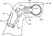
Figure 19 is the figure that expression head pipe constitutes.
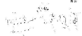
Figure 20 is a head pipe assembly drawing.
Figure 21 is an expression framework shortening state tubular axis portion and the figure that concerns of the position of guide roller down.
Figure 22 is an expression framework extended configuration tubular axis portion and the figure that concerns of the position of guide roller down.
Figure 23 represents the main body figure of connection terminal 161,162 mated condition.
Figure 24 is the figure that expression connection terminal guiding elements constitutes.
Figure 25 is the figure of the lock function of an expression tubular axis portion.
Figure 26 is the section-drawing of expression operating parts method of operation.
Figure 27 is the figure of the operating parts of expression lock-out state.
Figure 28 is the partial perspective block diagram of handle lockout mechanism.
Figure 29 is the figure (locking) that sees the handle lockout mechanism from handle bridge inboard.
Figure 30 is the figure (unlocking) that sees the handle lockout mechanism from handle bridge inboard.
Figure 31 is the figure of the extended configuration of expression Handle axis.
Figure 32 is the figure of the receiving state of expression Handle axis.
Figure 33 is the figure of the formation of expression front-wheel FW.
Figure 34 is the figure of the formation of expression trailing wheel RW.
Figure 35 is the figure of other formations of expression trailing wheel RW.
Figure 36 is the figure of expression to the bearing method of trailing wheel RW shown in Figure 35.
Figure 37 is the figure that expression power supply resettlement section constitutes.
Figure 38 is head lamp parts block diagrams.
Figure 39 is a head lamp light source portion block diagram.
Figure 40 is a head lamp light source portion front elevation.
Figure 41 is a head lamp light source portion lateral plan.
Figure 42 is the fragmentary, perspective view that the expression handle nearby constitutes.
Figure 43 is signal lamp parts block diagrams.
Figure 44 is signal lamp parts section-drawings.
Figure 45 is the back front elevation of electric bicycle.
Figure 46 is the section-drawing of connection terminal mated condition.
Figure 47 is the enlarged drawing of connection terminal contact portion.
The specific embodiment
Following present invention will be described in detail with reference to the accompanying most preferred embodiment.Fig. 1 is the block diagram as the shortening intake type electric bicycle of one embodiment of the invention.As shown in Figure 2, it mainly by the preceding framework 1 of supporting front-wheel FW and steering unit thereof, supporting as the back framework 2 of the trailing wheel RW of drive wheel and driver train thereof with allow that aforementioned forward and backward each framework 1,2 middle framework 3 that direction is slided and direction retractable twelve Earthly Branches brought forward is stated framework forwards, backwards forwards, backwards constitutes.
Preceding framework 1 is mainly by constituting with lower member: from the front fork 106 of left side cantilever support front-wheel FW, be linked to the handle bridge 108 of the handle post 107 of these front fork 106 upper ends, the pair of right and left Handle axis 102 (R that can slide up and down to supporting with handle bridge 108 two ends, W), aforementioned Handle axis 102 (R, L) the pair of right and left handle grips (R that links dividually on, L), with supporting aforementioned Handle axis 102 (R free to rotately, L) meter unit 101 on top, but free operant supporting aforementioned front fork 106, and include 2 103 (R of tubular axis portion who rearward extends, L) sound fork head pipe 103.
Back framework 2 is mainly by constituting with lower member; Keep the swing arm 201 of the trailing wheel RW of CD-ROM drive motor in the cantilever support of left side, can freely shake the axis of rocking 207 of the aforementioned swing arm 201 of ground axle suspension, by the coordinate 202 that aforementioned axis of rocking 207 is supporting free to rotately, support the pair of right and left side assembly 208 of aforementioned axis of rocking 207.Vehicle seat 203 and backrest 204 are installed on aforementioned seat pillar 202.
Aforementioned side assembly 208 (R, L) has pre-and post perforative 2 openings 205,206 up and down.In the bottom of aforementioned vehicle seat 203, accommodating secondary battery and function unit as described later in detail as drive source.Be provided with the right side 245 (R, L) of connection terminal who is electrically connected back framework 2 and middle framework 3 in two sides, each side assembly 208 (R, L) outside.
In such formation, the peristome of the deflector roll 302 (R, L) of framework 3 during the axial region 103 (R, L) of preceding framework 1 inserted, the peristome 205,206 of the side assembly 208 of aforementioned back framework 2 insert respectively wear aforementioned in the upper framework pipe 313 and the following framework pipe 314 of framework 3.
Battery is accommodated in seat 203 bottoms (with reference to Figure 37) with function unit, comprises power lead that connects this battery and the distribution L that is connected in the signal wire (SW) of function unit
1, L
2In, the distribution L that draws back along framework in the vehicle body left side
2Be connected to CD-ROM drive motor in the swing arm 201 by switch 209, in arriving by pair of terminals 245,345 simultaneously in the framework 3.
In addition, this distribution L
2, by each is provided with pair of terminals 161,162 (with reference to Figure 20) that cooperatively interacts at a deflector roll 302 (L) and tubular axis portion 103 (L) rear end, a tubular axis portion 103 (L) of framework 1 before arriving.And, distribution L
2Be connected to meter unit 101 by being located at also mutual chimeric pair of terminals 191,192 in Handle axis 102 (L) front end and handle bridge 108 two ends respectively.
The opposing party's distribution L that draws back along framework on the vehicle body right side
1Also be except that not connecting switch 209 this point, other are all the same, in the arrival in the framework 3 with preceding framework 1 in.
Secondly, the method that above-mentioned electric two-wheel vehicle is contained in the family expenses four-wheeled is illustrated.Electric bicycle of the present invention as the single automobile wagon of what is called or two automobile wagon, remains in car chamber ceiling height the tailstock trunk space of the seat rear, rear portion of the vehicle of vehicle rear guaranteeing, vehicle is accommodated with fore-and-aft direction shortening state.
Fig. 3 is the block diagram that the state of the tailstock trunk space that is accommodated in seat rear, rear portion of the electric bicycle with present embodiment is looked down from the top, rear portion of vehicle left side; Fig. 4 is its lateral plan.
Carrying in the tailstock trunk space of guaranteeing at the rear of the rear portion of vehicle seat 5 and taking in plate 4.In the present embodiment, can about accommodate 2 electric bicycles side by side, take in plate 4 about, be respectively equipped with guiding vehicles ditch 401 and wheel carrier 402.
In addition, in the present embodiment, for keeping vehicle seat design-calculated unitarity, as shown in Figure 5.The seat surface 51,71 of rear portion seat 5 and other seats 7 each other, vehicle seat back of the body frame 52,72 each other and handrail 53,73 make identical design each other, the backrest 703 that simultaneously stationarity is installed on other seats 7 is made with headrest 704 and aforementioned cart seat 203 and the design of backrest 204 general-duties.Therefore, just guaranteed to be contained in the design of rear portion seat 5 of state of seat pillar 202 of cart of tailstock trunk space and the unitarity in other seats 7 designs of the place ahead in pull-up.
Bottom illustrates the method that above-mentioned electric bicycle carries with reference to Fig. 6, Fig. 7 on vehicle.
As shown in Figure 6, the rear door that is used to carry the vehicle 8 of electric bicycle preferably is made of entrance door 851 of upspringing toward the top and 852 two of the exit doors of opening downwards; And preferably, exit door 852 is at the terrain clearance h of open mode
1The high h of axletree with electric bicycle
2Identical.
When electric bicycle is equipped on tailstock trunk space, as shown in Figure 7, at first catch handle grips 104 that front-wheel FW is pulled up on the exit door 852, again trailing wheel RW is pulled up on the exit door 852 and gets final product, perhaps also can catch the middle framework 3 of electric bicycle that whole vehicle body is lifted and go up, move in this state tailstock trunk space.
Bottom illustrates the accommodation method of above-mentioned electric bicycle with reference to Fig. 8~Figure 11.And the housing action summary only is described here, about being used to realize the back detailed description of being configured in of simple and easy each one of taking in.
Fig. 8 (a) shows the extended configuration that can walk.Make front-wheel FW, be inserted in the wheel guide groove 401 of taking in plate 4, be connected to after the wheel support spare 402, remove handle locking described later.Again left and right sides L type Handle axis 102 is changeed 90 ° to the inside, shown in Fig. 8 (b), Handle axis 102 is pressed to the below together with meter unit 101.At this moment, because connection terminal 191 (R, L), 192 (R, L) chimeric is disengaged, both separate, the disconnection that is electrically connected of power supply/signal wire (SW) and metering unit 101 and head lamp parts 105.
Secondly, shown in Fig. 9 (a), make described later before latch-release, make aforementioned before a tubular axis portion 103 (R, L) deflector roll 302 of framework 3 in aforementioned of framework 1 retreat.At this moment, because the chimeric releasing of framework 1 and the connection terminal 161,162 (with reference to Figure 20) of middle framework 3 before being electrically connected, both separate, be electrically connected disconnection between each framework.
Secondly, as shown in figure 10, after removing back described later lock, the switch 209 that advances on the side assembly 208 is located in operation, with trailing wheel RW forward direction driven at low speed, back framework 2 is advanced.At this moment, trailing wheel RW advances in wheel guide groove 401, makes the direction of framework consistent with the fore-and-aft direction of four wheeler.
The order of accommodating to four wheeler also is not limited thereto.For example, Handle axis 102 is being equipped on taking on the plate 4 of tailstock trunk space together with downwards state [Fig. 8 (b)] of meter unit 101 pushing, with vehicle body, in that to make front-wheel FW be connected under the state on the wheel carrier 402 the operation switch 209 that advances also passable.In this case, become back framework 2 to advance simultaneously with respect to framework 1 with middle framework 3.
Like this, when vehicle body shortened end, last was center pull-up seat pillar 202 as Fig. 9 (b), shown in Figure 11 with aforementioned swing arm 207, can make its seat 203 and backrest 204 turn to the position of back and the headrest positions of last seat 5 respectively.
Like this, in the present embodiment, cart is made of 1,2,3 of 3 frameworks and since preceding framework 1 and back framework 2 can with respect to middle framework 3 forwards, backwards direction be free to slide, the total length of the cart of receiving state is shortened more than existing.Owing to can fore-and-aft direction be shortened more, so can make the corresponding to tailstock trunk space that is contained in of fore-and-aft direction of the fore-and-aft direction and the four-wheeled of cart.Thereby, the seat pillar 202 of cart is rotated, can make its seat 203 play the backrest and the headrest of portion's seat 5 to the end with backrest 204.
That is, in the present embodiment, one one effect playing the rear portion of this vehicle seat owing to the seat 203 and the backrest 204 of the electric bicycle that can make the tailstock trunk space that is contained in four-wheeled realizes the function part communization, so can save space and expendable weight.
In addition, because in the present embodiment, and make body structure interlock mutually under reach, can disconnect each one and be electrically connected, operation is simplified in the time of so not only can making densification, and can prevent to forget the disconnection line.
In the present embodiment, with the rotating operation of aforementioned rocking arm 207 interlock mutually, shown in Fig. 3 and Fig. 9 (b), there is the connecting piece 323 that describes in detail later therefrom to give prominence to the side assembly bottom of framework 3 downwards, run through the opening 403 of taking in plate 4 again, be connected with the opposing party's (not shown) of the connecting piece that is loaded on body side.
Be provided with the electric terminal of charging electric wire on this connecting piece 323, link thus, when both mechanicalnesses are fixed, charging current feeds to the electric bicycle side from the power lead of vehicle side, to the secondary cell charge of electric bicycle.
The following structure of aforementioned each framework 1,2,3 and the mutual connect mechanism of describing in detail.
Figure 12 illustrate aforementioned in framework 3 main portion and with the expansion drawing of connect mechanism of back framework 2; Figure 13 is the figure of the cage construction of framework 3 in illustrating, the identical or equal part of symbolic representation as hereinbefore.
In framework 3, as previous Fig. 1 explanation, the pair of right and left framework body 301 (R, L) of configured in parallel linked it by tabular bridge spare 304 mutually in its forward lower part constitute.Aforementioned framework body 301 as shown in figure 13, is that preceding body frame 311 with U font roughly links with back body frame 312 usefulness upper framework pipes 313 and following framework pipe 314 and constitutes, and omits cyclic structurees in echelon.
Like this, because middle framework 3 is made of pair of right and left annular framework body 301 (R, L), not only can improve the intensity and the rigidity of framework in the present embodiment, and make its carrying that is equipped under the first-class situation of vehicle is also become than being easier to.
The preceding upper lateral part of each framework body 301 (R, L) be installed with can support with being free to slide before the pair of right and left deflector roll 302 (R, L) of head pipe 103 of framework 1.
The side assembly 208 of back framework 2 (R, L) has 2 openings 316,317 (seeing Figure 12) that run through along fore-and-aft direction thereon down, can run through aforementioned upper framework pipe 313 and following framework pipe 314 in this opening 316,317 in advance with being free to slide.Thus, but back framework 2 centering frameworks 3 forwards, backwards direction be supported with being free to slide.Go up 319 axis of opening that run through at left and right directions at side assembly 208 (R, L) and propping up aforementioned axis of rocking 207.
Each side assembly 208 in the side of its subtend, is being accommodated connecting piece 323, and this connecting piece 323 is connected by connecting rod mechanism 322,320,321 and aforementioned axis of rocking 207, and allows its up-and-down movement that it is being accommodated by guiding brake component 324,325.This connecting piece 323, Fig. 3 and Fig. 9 (b) are illustrated as described above, and being rotatedly connected of the aforementioned axis of rocking 207 during with pull-up seat pillar 202 moved and up-and-down movement.
Like this, in the present embodiment,, not only no longer need to link operation owing to can cart and four-wheeled be linked up by connecting piece 323 with being rotatedly connected of axis of rocking 207 is moving, and can prevent terminating in cart to four-wheeled not connecting state be placed on there.In addition, be provided with electric terminal on aforementioned connecting piece 323, the battery of cart can not need to connect in addition charging unit by the power source charges of four-wheeled by this connecting piece 323.So can utilize the charging of shifting time.
In aforementioned down framework pipe 314 inside, keep the back lockout mechanism, the aforementioned side assembly 208 relative slips of framework pipes 314 down that are used for locking or unlocking of this back lockout mechanism with the discrepancy action phase interlock of pedal 303.This back lockout mechanism mainly is made of with Rubber Parts housing 332 lock shaft 331, locking Rubber Parts 333, with aforementioned pedal 303 as operating parts.
Figure 14 is the figure of front [Figure 14 (a)] with the side [Figure 14 (b)] of the aforementioned lock shaft 331 of expression.Nearby formed the minor diameter 351 of inserting aforementioned pedal 303 at its leading section, portion nearby forms cam 384 in its back-end.Lock shaft 331 is being supported by axle at its two ends free to rotately, with the discrepancy of aforementioned pedal 303 operation interlock and rotating mutually.Aforementioned cam 384, its accumbency when pedal 303 is in collecting position, it was upright when pedal 303 was in extracting position.
Figure 15 is the figure of front [Figure 15 (a)] with the side [Figure 15 (b)] of the aforementioned Rubber Parts housing 332 of expression; Figure 16 is the surface [Figure 16 (a)] of the aforementioned locking Rubber Parts 333 of expression and the figure of side [Figure 16 (b)] and the back side [Figure 16 (c)].
Aforementioned locking Rubber Parts 333 is formed by the interior circular arc shaped elastic body that is connected to the inside face of Rubber Parts housing 332, and the central authorities at the surface and the back side have protrusion of surface 382 and back side projection 383 respectively.Locking Rubber Parts 333, its protrusion of surface 382 is outstanding laterally by the peristome 381 of aforementioned Rubber Parts housing 332, is mounted on this Rubber Parts housing 332 inboards.
Figure 17, the 18th is used to illustrate the figure of the lock out action of the preceding lockout mechanism that is made of above-mentioned constituent part.
At aforementioned pedal 303 taking-up states, as shown in figure 17, because cam 384 becomes length direction towards vertical direction cut-off standing position gesture, the back side projection 383 that will be locked Rubber Parts 333 by the both ends of cam 384 is released, and its protrusion of surface 382 also highlights to foreign side greatly from the peristome 381 of Rubber Parts shell 332.The protrusion of surface that highlights 382 connects the peristome 385 (seeing Figure 12) of framework pipes 314 down, combines with peristome 386 (seeing Figure 12) on being located at aforementioned side assembly 208, stops its slip.
On the other hand, accommodated state at aforementioned pedal 303, as shown in figure 18, because the length direction of cam 384 is got the accumbency posture towards horizontal direction, the protrusion of surface 382 of locking Rubber Parts 333 is contained in inside.Thereby, can slide along the aforementioned framework pipe down 314 of side assembly 208.
Like this, in the present embodiment since by with the discrepancy of pedal 303 operation interlock mutually, back framework 2 can be locked for the slip of middle framework 3 or be unlocked, and does not need special latch-release lock operation so become.
Following structure to framework 1 before aforementioned reaches and the connect mechanism of aforementioned middle framework 3 is illustrated.
Figure 19 is the expansion drawing as the head pipe 103 of the main portion of preceding framework 1.Head pipe 103 can freely be handled the twelve Earthly Branches brought forward and states the base portion 103 (c) of the through hole of front fork 106 (113) and from this base portion 103 (c) pair of right and left tubular axis portion 103 (R, L) of extension formation rearward abreast, see on the whole to be the tuning fork shape by having.The operating parts 141 (R, L) of lockout mechanism before the rearward end of each tubular axis portion 103 (R, L) is assembled with, this operating parts 141 (R, L) the extended configuration of cart promptly the walking state be used for stoping this preceding framework 1 relatively in the slip of framework 3.
Operating parts one side's 141 (R) mainly by hook pipe 151, substrate 152, bar plate 153, bar 154, in conjunction with pin 155, constitute with cover 156.Operating parts the opposing party's 141 (L), except aforementioned other are identical in conjunction with the pin 155 by replacing in conjunction with tube 160, wherein in conjunction with tube 160 by in conjunction with inner core 157, in conjunction with urceolus 158 be sandwiched in this inner core 157 and the fastening ball 159 of 158 of urceolus constitutes.
In the Fabrication procedure of this cart, as shown in figure 20, the deflector roll 302 of framework 3 then, was assembled into aforementioned operation part 141 rearward end of each tubular axis portion 103 (R, L) during a tubular axis portion 103 (R, L) inserted in advance.
The positive connection terminal 162 and female terminals 161 that are electrically connected, when shortening both electricity are cut off that is used for guaranteeing 1,2 of each frameworks when stretching is being set respectively on the operating parts 141 of the deflector roll 302 of middle framework 3 and preceding framework 1.Aforementioned female terminals 161 is passed through installation component 163 with the top of screw retention in deflector roll 302.The sun connection terminal 162 with screw retention on the substrate 152 of operating parts 141.
Figure 21 is that the expression framework shortens state, is a tubular axis portion 103 (R, L) of receiving state and the figure of the position relation of deflector roll 302.Aforementioned female terminals 161 is covered by cover 341 with deflector roll 302; Sun connection terminal 162 is covered by cover 149.
Shorten state at framework, deflector roll 302 is positioned at the place ahead of axial region 103 (R, L), because aforementioned male connection terminal 162 separates 3 one-tenth electric off-states of preceding framework 1 and middle framework with female terminals 161.141 one-tenth orthostatisms of operating parts.
When be stretched over from this shortening state maximum extension position shown in Figure 22 during walking states, deflector roll 302 slides into the terminal part of axial region 103 (R, L), aforementioned male connection terminal 162 and female terminals 161 tablings.Thus, because both are electrically connected, framework 1 and middle framework 3 is electrically connected before can guaranteeing.
Like this, in the present embodiment, be disconnected owing to each one under the state of accommodating that shortens at framework is electrically connected, even operated switch etc. mistakenly at this state of accommodating, the Denso machine can not move yet.
In addition, owing to guaranteed in the body structure maximum extension position, so can prevent beyond maximum extension position, be the walking of incomplete extended configuration by only being electrically connected of carrying out of each connection terminal 161,162.
Figure 23 is the block diagram of the chimerism of aforementioned each connection terminal 161,162 of expression.Formed the guiding elements 164,163 that is used for when chimeric, both being guided to relatively the appropriate location on the top of each connection terminal 161,162.As shown in figure 24, guiding elements 164 has through hole 163b, has formed tapering 164a at its open end, so that in the easy pin member 163a importing impenetrating mouth 163b with guiding elements 163.
Figure 46 is the section-drawing of aforementioned each connection terminal 161,162 mated condition, as hereinbefore symbolic representation identical or equal part.
In addition, in the present embodiment, because not only aforementioned guiding elements 164,163 has formed the tapering, on the fitting portion of connection terminal 161,162, also formed tapering 161a, the 162a that both are cooperated, so even how many relative positions of connection terminal 161,162 produces a little errors, owing to both can be guided to positive relatively assigned position, still can keep good fit.
Also have, in the present embodiment, the contact 198 of positive connection terminal 162 is spring pins, and shown in Figure 47 amplified, spring pin 196 elasticity that highlight from the front end elasticity of contact 198 were pressed to the recess 197a of the front end of the contact 197 that is located at female terminals 161.Thereby, owing to the vibration and the position changing of the relative positions of 161,162 of connection terminals can be absorbed, so can often keep being electrically connected of good framework connecting part.
Figure 26 is the section-drawing of aforementioned each operating parts 141 (R, L).In the middle of the terminal part of tubular axis portion 103 (R, L) to the end that deflector roll 302 picture is slided as shown in Figure 22, grabbing each operating parts 141 respectively with the right-hand man, accumbency posture from the orthostatism of Figure 26 (a) to Figure 26 (b), east side operation part 141 (R) to anticlockwise direction, left-hand operation spare 141 (L) along 90 ° of clockwise counter-rotatings.
Secondly, pinching the bar 154 of each operating parts 141, shown in Figure 26 (c), they are being slided to the inside.At this moment, outstanding from opening 148 (R) in east side operation part 141 (R) in conjunction with pin 155, outstanding from opening 148 (L) in left-hand operation spare 141 (L) in conjunction with tube 160, make in conjunction with pin 155 and insert in conjunction with tube 160, by aforementioned fastening ball 159 it is interfixed.Thus, as shown in figure 27, because left and right sides axial region 103 (R, L) mechanical link, so can improve framework rigidity when walking.
In addition, at the walking states of operating parts 141 accumbency, as shown in figure 25, the hook pipe 151 (with reference to Figure 19) in the tubular axis portion 103 (R, L) turns to the inside 90 °, makes it to combine with deflector roll 302 side mouth 391 with the side mouth 191 of axial region 103 (R, L).Thus, deflector roll 302 is locked with axial region 103 (R, L), forbids both slide relative.
Like this, in the present embodiment, because left and right sides operating parts 141 is rotated with regard to 3 lockings of the 1 centering framework of framework before not only can making, and also operating parts becomes easy near configuration so make to lock/unlock to operate.
Bottom illustrates the lockout mechanism of Handle axis 102.Figure 28 is the lockout mechanism partial perspective block diagram of expression Handle axis 102 and handle bridge 108; Figure 29, the 30th sees the figure of this handle lockout mechanism from handle bridge 108 inboards.This handle lockout mechanism, be located at respectively Handle axis 102 about, here, be that example is illustrated with the mechanism that is located on the right side Handle axis 102 (R).
The handle lockout mechanism is made of with thrust piece 185 and thrust piece guide 186 L type control lever 181, bar 182, eccentric mechanism 193, bar 184.At extended configuration shown in Figure 31, as shown in figure 29, because L type control lever 181 is pushed into the inboard of handle bridge 108, the front end of thrust piece 185 is invaded the opening 187 that is located at L type Handle axis 102 sidepieces, stops its slip.
In contrast, when pulling out L type control lever 181, as shown in figure 30, eccentric mechanism 183 is pulled out thrust piece 185 by aforementioned rod 184 to anticlockwise motion.Thereby, operation left and right sides L type control lever 181, releasing handle lock, following pushing hands arbor 102 under this state, then shown in figure 32, Handle axis 102 relative handle bridges 108 slide downwards.
The lower end of handle bridge 108 both sides and Handle axis 102 (R, L) be provided with and be electrically connected aforementioned before same connection terminal 191 (R, L), 192 (R, the L) of connection terminal 161,162 of framework 1 and middle framework 3, because aforesaid slip, chimeric being disengaged of aforementioned each connection terminal 191 (R, L), 192 (R, L) and separating promptly disconnected being electrically connected of handle bridge 108 and Handle axis 102.
Figure 33 is the expansion drawing of the formation of expression front-wheel FW, as hereinbefore symbolic representation identical or be equal to part.
Front-wheel FW mainly is made of with tire 137 mounting flange 133, front-wheel 134, disk rotor 135, and disk rotor 135 relative front-wheels 134 are with screw retention.Aforementioned front-wheel FW is run through by the front wheel spindle 199 that extends from the front end of front fork 106 with left and right sides wheel cap 131,138 and cantilever support, tighten up by nut 132, brake caliper 136 with wheel cover 138 with screw retention on front fork 106.Clamp cover 139 is fixed on the wheel cap 138.
Figure 34 is the expansion drawing that expression trailing wheel RW constitutes, and symbolic representation is identical or be equal to part as hereinbefore.
Rocking arm 201 has cartridge type drg 239 and hind axle 240, stator 231 with screw retention on periphery.In wheel 237 sides of trailing wheel, sensor 235 and magnet rotor 233 be coaxial to be inserted and is worn and fixing by snap ring 232.
Figure 35 is the expansion drawing of other formations of expression trailing wheel RW, and symbolic representation is identical or be equal to part as hereinbefore.
Trailing wheel RW mainly by rear tyre 236 take turns 237 with it, the CD-ROM drive motor 226, the disk rotor 229 that are contained in wheel 237 inboards of trailing wheel constitute with its clamp 288, aforementioned CD-ROM drive motor 226 comprises stator 226S and the magnet rotor 226R that rotates in this stator outside.
The wheel 237 of aforementioned trailing wheel is supported by hind axle 286 by center shaft 281 and left and right sides bearing 225,282.On hind axle 286, put on left and right sides exclusion seal 224,283, sleeve 284 and carriage 223, tighten fixing facing to back vent 289 by nut 222.
By carriage 223 the stator 226S of CD-ROM drive motor 226 is fixed in back vent 289.Aforementioned disk rotor 229 is tightened the right side of the wheel 237 that is fixed in trailing wheel by screw 230.
Figure 37 is the figure that is illustrated in the formation of the power supply resettlement section 244 of guaranteeing aforementioned seat 203 bottoms.In power supply resettlement section 244, accommodated and many single batteries have been arranged as laminated and skin packaging is the 2 Battery pack groups 251 (R, L) of one and function unit 242 and the large bulk capacitance 243 that comprises cut-off switch 247,248, DC-DC conv.
Figure 38 is the block diagram of aforementioned head lamp parts 105; Figure 39 is the block diagram that is built in the light source portion 175 of head lamp parts 105; Figure 40 is the front elevation of aforementioned light source portion 175; Figure 41 is its lateral plan.
In the light source portion 175 of present embodiment, shown in Figure 40,41, it has comprised basal component 189, be loaded on the substrate 178 of this basal component 189 and remained a plurality of LED177 of three-dimensional (solid) by basal component 189.
In aforementioned substrates member 189, be provided with a plurality of openings in the basal plane 176 upper edge ranks directions of bending, form step-like abutment face 188 in each open bottom.White high-brightness LED 177, its part is contained in the aforementioned opening from basal plane 176 with only forwards exposing specified length.Each LED177 is connected under the state of aforementioned abutment face 188 inside being pushed to it, and its electrode pin soldering is fixed on the aforesaid base plate 178.Thereby the exposed length of each LED177 is by the step difference regulation of aforementioned abutment face 188.On aforesaid base plate 178, carrying the starting circuit that is used to light aforementioned each LED177.
Like this, as according to present embodiment, can be under without the situation of curved substrate three-dimensional configuration LED.In addition, because the height of LED and sensing do not rely on the soldering of substrate 178 and LED electrode, can and there be individual difference ground stereoscopic configurations LED with high luminous intensity distribution precision.
Figure 42 is the part transparent view of expression right hand grip formation nearby.On handle tube 170, adorn signal lamp parts 166 described later, around it, adorning handle 104.When the medial end of holding handle 104 with the right hand promptly during this handle,, be provided with brake rod 167 and accelerator rod 168 in its thumb scope in one's power.The aperture of accelerator rod 168 detects by quickening jaw opening sensor 169.
Figure 43 is the block diagram of aforementioned signal lamp parts 166, and Figure 44 is its section-drawing [Figure 44 (a)] and end elevation view [Figure 44 (b)].
The signal lamp parts 166 of present embodiment, as shown in figure 44, have the support tube 171 that wears aforementioned handle tube 170, substrate 179, bulging is circular support 173 and 5 high-brightness LEDs 174 of dome shape in support tube 171 1 ends central authorities, LED174 exposes the end as shown in figure 43, is covered by translucent cover 172.
Aforementioned 5 high-brightness LEDs 174, wherein 1 is the center, other 4 LED around it, at interval 90 ° and make optical axis respectively from center shaft outwards the side stagger some, be fixed on the aforesaid base plate 179.The optical axis adjustment of each LED174 is carried out like this: each LED174 is inserted into the sphere portion that its bottom surface is resisted against circular support 173, its electrode is fixed on the substrate 179.
As formation, can be by the luminous intensity distribution feature correct provisioning of the shape of circular support 173 with signal lamp.In addition, because with the small-sized handle end that is formed at of signal lamp, so the operating characteristic of handle is not damaged by signal lamp can.
Figure 45 is the back front elevation of electric bicycle, as hereinbefore identical the or equal part of symbolic representation.
In the present embodiment, dispose a plurality of red LED three-dimensionally, constitute brake lamp 361 (R, L) at aforementioned framework body 312 (R, L) rear portion; Dispose orange LED at its downside three-dimensionally, constitute signal lamp 362 (R, L).Present 203 rear configuration number plate 6.
Like this, in the present embodiment, owing to as head lamp, brake lamp, adopted LED, can realize economize on electricityization necessary concerning elec. vehicle with the light source of signal lamp.In addition, owing to having adopted LED to relax the restriction in the design, can improve its aesthetics as light source.
As adopt the present invention, can obtain following effect.
(1) owing to making the forwards, backwards direction slip of the relative middle framework with rear framework both sides of front framework, can Make fore-and-aft direction compacter.
(2) because middle framework is made the pair of right and left ring-type, the intensity that not only can improve framework with Rigidity, and be equipped on easily carrying in the situation such as vehicle.
(3) owing on middle framework, established pedal, just can save the special use that is used for fixing pedal and support.
(4) for middle framework, owing to be located at top, be located at the bottom with the lockout mechanism of back framework with the lockout mechanism of preceding framework, each lockout mechanism leaves configuration mutually, so can improve the Design freedom of each lockout mechanism.
(5),, do not need to be used to the operation that locks or unlock so do not need to establish in addition lock operation spare owing to framework during interlock makes mutually with the turnover of pedal is locked or unlock with the back framework yet.
(6) since centering framework and preceding framework lock and a pair of operating parts of the operation that unlocks is close configuration make locking and unlock to operate to become easy.In addition, at lock-out state because each operating parts links mutually, preceding framework circlewise, can improve the framework rigidity in when walking.
Claims (7)
1. electric bicycle, it comprises: the back framework of preceding framework, supporting wheels and the drive element of supporting front-wheel and the framework and the back middle framework of framework before direction is free to slide the twelve Earthly Branches brought forward and states forwards, backwards, it is characterized in that aforementioned middle framework is made of configured in parallel pair of right and left ring-type framework.
2. by the described electric bicycle of claim 1, it is characterized in that having the pedal that can freely fold at aforementioned each ring-type framework sidepiece.
3. by the described electric bicycle of claim 1, it is characterized in that having taillight at the rear portion of aforementioned each ring-type framework.
4. by the described electric bicycle of claim 1, it is characterized in that, aforementioned ring-type framework is the roughly trapezoidal of framework top and framework lower parallel, aforementioned preceding framework can be combined on the bearing set that is arranged at aforementioned framework top with being free to slide, have first blocking device of this joint portion of locking;
Aforementioned back framework has the side assembly, makes aforementioned side assembly can be combined in aforementioned framework top, framework bottom with being free to slide, has second blocking device of this joint portion of locking.
5. by the described electric bicycle of claim 4, it is characterized in that, in aforementioned framework bottom, lock shaft be set, connect pedal, connect cam at the rear portion of aforementioned lock shaft in the front portion of aforementioned lock shaft,
Operate aforementioned cam with being folded to connect of aforementioned pedal movingly, aforementioned framework bottom and aforementioned side assembly are freely locked.
6. by the described electric bicycle of claim 4, it is characterized in that aforementioned preceding framework has the pair of right and left axial region that extends to vehicle body rear approximate horizontal; The framework top of aforementioned each ring-type framework has the bearing set that can be free to slide the supporting axial region; Aforementioned first blocking device stops the slip of axial region with respect to aforementioned bearing set, and aforementioned each axial region portion in its back-end has a pair of operating parts of removing aforementioned first blocking device.
7. by the described electric bicycle of claim 6, it is characterized in that aforementioned a pair of operating parts is bonded mutually when aforementioned first blocking device is in the lock state.
Applications Claiming Priority (4)
| Application Number | Priority Date | Filing Date | Title |
|---|---|---|---|
| JP266552/2001 | 2001-09-03 | ||
| JP2001266552 | 2001-09-03 | ||
| JP304450/2001 | 2001-09-28 | ||
| JP2001304450A JP4514085B2 (en) | 2001-09-03 | 2001-09-28 | Electric motorcycle |
Publications (2)
| Publication Number | Publication Date |
|---|---|
| CN1403332A CN1403332A (en) | 2003-03-19 |
| CN1288029C true CN1288029C (en) | 2006-12-06 |
Family
ID=26621575
Family Applications (1)
| Application Number | Title | Priority Date | Filing Date |
|---|---|---|---|
| CN02141608.7A Expired - Fee Related CN1288029C (en) | 2001-09-03 | 2002-09-02 | Electric bicycle and its carring method |
Country Status (4)
| Country | Link |
|---|---|
| JP (1) | JP4514085B2 (en) |
| CN (1) | CN1288029C (en) |
| FR (1) | FR2829097B1 (en) |
| IT (1) | ITTO20020752A1 (en) |
Cited By (1)
| Publication number | Priority date | Publication date | Assignee | Title |
|---|---|---|---|---|
| CN103180202A (en) * | 2010-09-29 | 2013-06-26 | Lit摩托车公司 | Foldable scooter |
Families Citing this family (8)
| Publication number | Priority date | Publication date | Assignee | Title |
|---|---|---|---|---|
| JP3647406B2 (en) * | 2001-10-04 | 2005-05-11 | ジェイディジャパン株式会社 | Motorcycle with auxiliary motor |
| FR2913396B1 (en) * | 2007-03-08 | 2009-06-12 | Fabrice Marion | VEHICLE WITH TWO WHEELS WITH VARIABLE SIZE |
| CN103889835A (en) | 2011-08-22 | 2014-06-25 | Lit摩托车公司 | Vehicle frame and component design for efficient and compact packaging |
| JP5620898B2 (en) * | 2011-10-26 | 2014-11-05 | 本田技研工業株式会社 | Electric vehicle |
| ES2491415B1 (en) * | 2013-03-05 | 2015-06-25 | Antonio Guerra Navas | Multi-size and folding bike and tricycle chassis |
| CN105329390B (en) * | 2015-10-27 | 2018-01-30 | 谭春升 | A kind of folded bicycle |
| FR3051431B1 (en) | 2016-05-18 | 2018-06-22 | Peugeot Citroen Automobiles Sa | SUPPORT FOR STORING A ROLLER |
| CN109562681B (en) | 2016-07-28 | 2022-05-10 | 福特全球技术公司 | Multi-mode transportation system and mobility device |
Family Cites Families (10)
| Publication number | Priority date | Publication date | Assignee | Title |
|---|---|---|---|---|
| FR1058560A (en) * | 1952-06-20 | 1954-03-17 | Retem | Lightweight scooter with reduced dimensions |
| JPS4935072Y2 (en) * | 1971-08-03 | 1974-09-24 | ||
| JPH02249783A (en) * | 1989-03-24 | 1990-10-05 | Honda Motor Co Ltd | Foldable motorcycle |
| JPH0321579A (en) * | 1989-06-16 | 1991-01-30 | Honda Motor Co Ltd | Collapsible motorcycle |
| JPH0362585U (en) * | 1989-10-16 | 1991-06-19 | ||
| GB2250725A (en) * | 1990-12-11 | 1992-06-17 | Bird Peter Stephen | Dimensionally adjustable cycle |
| JPH04130593U (en) * | 1991-05-24 | 1992-11-30 | 三菱自動車エンジニアリング株式会社 | folding bike |
| DE9404300U1 (en) * | 1993-09-16 | 1994-05-05 | Bernds, Thomas, 32756 Detmold | bicycle |
| DE29920367U1 (en) * | 1999-11-19 | 2000-01-05 | Biria GmbH, 68535 Edingen-Neckarhausen | Bicycle that can be scaled down for transport, especially scooter wheels |
| JP2002160688A (en) * | 2000-11-27 | 2002-06-04 | Mitsugi Kashiwagi | Folding bicycle stored in bag |
-
2001
- 2001-09-28 JP JP2001304450A patent/JP4514085B2/en not_active Expired - Fee Related
-
2002
- 2002-08-26 IT IT000752A patent/ITTO20020752A1/en unknown
- 2002-08-27 FR FR0210629A patent/FR2829097B1/en not_active Expired - Fee Related
- 2002-09-02 CN CN02141608.7A patent/CN1288029C/en not_active Expired - Fee Related
Cited By (1)
| Publication number | Priority date | Publication date | Assignee | Title |
|---|---|---|---|---|
| CN103180202A (en) * | 2010-09-29 | 2013-06-26 | Lit摩托车公司 | Foldable scooter |
Also Published As
| Publication number | Publication date |
|---|---|
| FR2829097A1 (en) | 2003-03-07 |
| ITTO20020752A0 (en) | 2002-08-26 |
| FR2829097B1 (en) | 2008-02-22 |
| CN1403332A (en) | 2003-03-19 |
| JP4514085B2 (en) | 2010-07-28 |
| JP2003146280A (en) | 2003-05-21 |
| ITTO20020752A1 (en) | 2003-03-04 |
Similar Documents
| Publication | Publication Date | Title |
|---|---|---|
| CN1251918C (en) | Bicycle and folding method of bicycle | |
| CN1234552C (en) | Electrically-driven vehicle | |
| CN1308164C (en) | Loading cycle of two-wheel cycle and loading method for two-wheel cycle | |
| CN1288029C (en) | Electric bicycle and its carring method | |
| CN104602936B (en) | Saddled electric vehicle | |
| CN1071231C (en) | Structure of arranging batteries in bicycle with electric power aid | |
| CN1342123A (en) | Electric vehicle | |
| CN1605539A (en) | Brake tongs braced structure of automatic bicycle | |
| CN1605530A (en) | Goods strorage structure for miniature motorcycle | |
| CN1280150C (en) | Support and windscreen construction of fairings for mopeds | |
| CN1071662C (en) | Electrically-powered mopeol | |
| CN1071663C (en) | Electrically-powered moped | |
| CN1376607A (en) | Windshield structure of powered bicycle | |
| CN1282582C (en) | Moped | |
| CN1412054A (en) | Battery assembling-disassembling structure for electric two-wheeled motorcycle | |
| CN1281432C (en) | Vehicle with solar battery | |
| CN101062704A (en) | Motorcycle | |
| CN1272213C (en) | Handle bar device for steering | |
| CN1150104C (en) | Electric booster device | |
| CN1907798A (en) | Luggage fixing arrangement for low floor-type vehicle and low floor-type vehicle | |
| CN1743218A (en) | Small motorcycle | |
| CN1340435A (en) | Electric-aided bicycle | |
| CN1258458C (en) | Cover structure of bicycle | |
| CN1229257C (en) | Article container structure of two-wheel motorcycl | |
| CN1359823A (en) | Steering device for bicycle and steering device folding method |
Legal Events
| Date | Code | Title | Description |
|---|---|---|---|
| C06 | Publication | ||
| PB01 | Publication | ||
| C10 | Entry into substantive examination | ||
| SE01 | Entry into force of request for substantive examination | ||
| C14 | Grant of patent or utility model | ||
| GR01 | Patent grant | ||
| C17 | Cessation of patent right | ||
| CF01 | Termination of patent right due to non-payment of annual fee |
Granted publication date: 20061206 Termination date: 20110902 |