CN1283364C - Method and apparatus for uniform particle loading of vessels - Google Patents
Method and apparatus for uniform particle loading of vessels Download PDFInfo
- Publication number
- CN1283364C CN1283364C CN03127565.6A CN03127565A CN1283364C CN 1283364 C CN1283364 C CN 1283364C CN 03127565 A CN03127565 A CN 03127565A CN 1283364 C CN1283364 C CN 1283364C
- Authority
- CN
- China
- Prior art keywords
- particle
- hole
- assembly
- loading arm
- dispersion
- Prior art date
- Legal status (The legal status is an assumption and is not a legal conclusion. Google has not performed a legal analysis and makes no representation as to the accuracy of the status listed.)
- Expired - Fee Related
Links
Images


Classifications
-
- B—PERFORMING OPERATIONS; TRANSPORTING
- B65—CONVEYING; PACKING; STORING; HANDLING THIN OR FILAMENTARY MATERIAL
- B65G—TRANSPORT OR STORAGE DEVICES, e.g. CONVEYORS FOR LOADING OR TIPPING, SHOP CONVEYOR SYSTEMS OR PNEUMATIC TUBE CONVEYORS
- B65G69/00—Auxiliary measures taken, or devices used, in connection with loading or unloading
- B65G69/04—Spreading out the materials conveyed over the whole surface to be loaded; Trimming heaps of loose materials
- B65G69/0458—Spreading out the materials conveyed over the whole surface to be loaded; Trimming heaps of loose materials with rotating means, e.g. tables, arms
-
- B—PERFORMING OPERATIONS; TRANSPORTING
- B01—PHYSICAL OR CHEMICAL PROCESSES OR APPARATUS IN GENERAL
- B01J—CHEMICAL OR PHYSICAL PROCESSES, e.g. CATALYSIS OR COLLOID CHEMISTRY; THEIR RELEVANT APPARATUS
- B01J8/00—Chemical or physical processes in general, conducted in the presence of fluids and solid particles; Apparatus for such processes
- B01J8/0015—Feeding of the particles in the reactor; Evacuation of the particles out of the reactor
- B01J8/002—Feeding of the particles in the reactor; Evacuation of the particles out of the reactor with a moving instrument
-
- B—PERFORMING OPERATIONS; TRANSPORTING
- B01—PHYSICAL OR CHEMICAL PROCESSES OR APPARATUS IN GENERAL
- B01J—CHEMICAL OR PHYSICAL PROCESSES, e.g. CATALYSIS OR COLLOID CHEMISTRY; THEIR RELEVANT APPARATUS
- B01J8/00—Chemical or physical processes in general, conducted in the presence of fluids and solid particles; Apparatus for such processes
- B01J8/0015—Feeding of the particles in the reactor; Evacuation of the particles out of the reactor
- B01J8/003—Feeding of the particles in the reactor; Evacuation of the particles out of the reactor in a downward flow
-
- B—PERFORMING OPERATIONS; TRANSPORTING
- B01—PHYSICAL OR CHEMICAL PROCESSES OR APPARATUS IN GENERAL
- B01J—CHEMICAL OR PHYSICAL PROCESSES, e.g. CATALYSIS OR COLLOID CHEMISTRY; THEIR RELEVANT APPARATUS
- B01J8/00—Chemical or physical processes in general, conducted in the presence of fluids and solid particles; Apparatus for such processes
- B01J8/0015—Feeding of the particles in the reactor; Evacuation of the particles out of the reactor
- B01J8/004—Feeding of the particles in the reactor; Evacuation of the particles out of the reactor by means of a nozzle
-
- B—PERFORMING OPERATIONS; TRANSPORTING
- B01—PHYSICAL OR CHEMICAL PROCESSES OR APPARATUS IN GENERAL
- B01J—CHEMICAL OR PHYSICAL PROCESSES, e.g. CATALYSIS OR COLLOID CHEMISTRY; THEIR RELEVANT APPARATUS
- B01J8/00—Chemical or physical processes in general, conducted in the presence of fluids and solid particles; Apparatus for such processes
- B01J8/02—Chemical or physical processes in general, conducted in the presence of fluids and solid particles; Apparatus for such processes with stationary particles, e.g. in fixed beds
- B01J8/0242—Chemical or physical processes in general, conducted in the presence of fluids and solid particles; Apparatus for such processes with stationary particles, e.g. in fixed beds the fluid flow within the bed being predominantly vertical
- B01J8/025—Chemical or physical processes in general, conducted in the presence of fluids and solid particles; Apparatus for such processes with stationary particles, e.g. in fixed beds the fluid flow within the bed being predominantly vertical in a cylindrical shaped bed
-
- B—PERFORMING OPERATIONS; TRANSPORTING
- B01—PHYSICAL OR CHEMICAL PROCESSES OR APPARATUS IN GENERAL
- B01J—CHEMICAL OR PHYSICAL PROCESSES, e.g. CATALYSIS OR COLLOID CHEMISTRY; THEIR RELEVANT APPARATUS
- B01J8/00—Chemical or physical processes in general, conducted in the presence of fluids and solid particles; Apparatus for such processes
- B01J8/02—Chemical or physical processes in general, conducted in the presence of fluids and solid particles; Apparatus for such processes with stationary particles, e.g. in fixed beds
- B01J8/04—Chemical or physical processes in general, conducted in the presence of fluids and solid particles; Apparatus for such processes with stationary particles, e.g. in fixed beds the fluid passing successively through two or more beds
- B01J8/0446—Chemical or physical processes in general, conducted in the presence of fluids and solid particles; Apparatus for such processes with stationary particles, e.g. in fixed beds the fluid passing successively through two or more beds the flow within the beds being predominantly vertical
- B01J8/0461—Chemical or physical processes in general, conducted in the presence of fluids and solid particles; Apparatus for such processes with stationary particles, e.g. in fixed beds the fluid passing successively through two or more beds the flow within the beds being predominantly vertical in two or more cylindrical annular shaped beds
- B01J8/0465—Chemical or physical processes in general, conducted in the presence of fluids and solid particles; Apparatus for such processes with stationary particles, e.g. in fixed beds the fluid passing successively through two or more beds the flow within the beds being predominantly vertical in two or more cylindrical annular shaped beds the beds being concentric
-
- B—PERFORMING OPERATIONS; TRANSPORTING
- B01—PHYSICAL OR CHEMICAL PROCESSES OR APPARATUS IN GENERAL
- B01J—CHEMICAL OR PHYSICAL PROCESSES, e.g. CATALYSIS OR COLLOID CHEMISTRY; THEIR RELEVANT APPARATUS
- B01J2208/00—Processes carried out in the presence of solid particles; Reactors therefor
- B01J2208/00743—Feeding or discharging of solids
- B01J2208/00752—Feeding
-
- B—PERFORMING OPERATIONS; TRANSPORTING
- B01—PHYSICAL OR CHEMICAL PROCESSES OR APPARATUS IN GENERAL
- B01J—CHEMICAL OR PHYSICAL PROCESSES, e.g. CATALYSIS OR COLLOID CHEMISTRY; THEIR RELEVANT APPARATUS
- B01J2208/00—Processes carried out in the presence of solid particles; Reactors therefor
- B01J2208/02—Processes carried out in the presence of solid particles; Reactors therefor with stationary particles
- B01J2208/023—Details
- B01J2208/024—Particulate material
- B01J2208/025—Two or more types of catalyst
Abstract
Apparatus for dispersing particles flowing from an orifice comprising a deflecting surface disposed relative to the orifice, wherein the deflecting surface is fixed relative to the orifice, whereby particles flowing from the orifice can impinge upon and can be dispersed by the deflecting surface. The invention also includes an apparatus for loading particles into a vessel comprising particle hopper storage means; at least one rotary loading arm comprising a conduit having a first end and a second end, wherein the first end is in particle flow communication with the particle hopper storage means, and wherein a portion of the conduit has a plurality of orifices disposed between the first and the second end; and a plurality of particle dispersal assemblies, each particle dispersal assembly being disposed adjacent to an orifice, wherein each particle dispersal assembly comprises a deflecting surface which is fixed relative to the orifice such that particles flowing from the orifice can impinge upon and can be dispersed by the deflecting surface. This apparatus includes drive means for rotating the at least one rotary loading arm.
Description
Technical field
The present invention relates to the method and apparatus of container single-size charging.
Background technology
By evenly flowing of a fluid of material material packed bed, be important to effective operation of pressure or temperature swing adsorption systems and fixed bed chemical reaction system.Any remarkable radial variations of fluid axial velocity can reduce fluid and the effective of solid contacts, thereby reduces the purity and the recovery of product in the adsorption system, and reduces total conversion ratio in the chemical reactor.Evenly flowing of fluid by the granular materials packed bed can be by loading granular materials carefully in container, have continuously and homogenizing bed realization of filling in lectulum hole to form one.
In the art, used the grain bed that dissimilar particle stowages forms container.First and a method the earliest are to topple over charging in these methods, and wherein granular materials is filled into simply in the container and is manual smooth.In the method, the bed uniformity is not controlled, and particle do not lay well, although can be in toppling over or use vibration to adjust bed thereafter.Because it is homogenizing bed not form a filling, this method does not guarantee to flow through the even radial distribution of bed fluid.
In the second method of having used, form particle layers by a succession of a large amount of stratum granulosums of sedimentation in container.A known pattern is the throwing loading method, and it uses a chute or flexible pipeline that the funnel above the particulate from reservoir device is transported to bed face.Along with the carrying out of container loading, chute raises gradually and finishes until the bed charging.Because particle is random orientation and inhomogeneous laying,, this method do not fill even bed so not producing.
The third method of using is a radial dispersion, and wherein particle throws away from the rotary-dispersing apparatus radial outward, drop to bed face with the individual particle form substantially then.In the method, grain flow drops on the whirligig, for example a disk or a series of horizon bar, and whirligig blocks grain flow, and drop at individual particle and to give its radial motion in the bed face process.By making the single landing of particle, the radial dispersion method can form fills charging, but the dispersion of particle on bed face is at random, and therefore final bed face may be inhomogeneous.
The 4th kind of method of particle charging is described to disperse landing.In the method, particle passes through one or more holes, and is dispersed on the bed face.The hole can be fix or move relative to bed.In one style, the fixed disc that a series of number of perforations increases gradually is divided into more and more thinner stream with grain flow.Although final particle tributary may be that the not single landing of particle is unless descent altitude is very big uniformly.Along with increasing of bed face, descent altitude reduces, and the result causes loading density to reduce.The pattern utilization that disperses landing method to upgrade has the hollow rotating arm in spaced hole, and when arm rotated above bed, the hole that the grain flow super-interval is arranged also drop to bed face.This method produces fills equal uniform flow, and the method for optimizing that loads of particle normally.
The particle that uses in this area disperses in the landing loading method, and particle is typically scattered by a large amount of apertures of flowing through, to obtain the decentralization of expectation.Disperse if can obtain suitable charging, then preferably the bigger hole by less amount disperses.That announce below and by the defined the present invention of claim subsequently, a kind of dispersion landing method of improved use spiral arm is provided, hole that this spiral arm utilization is big relatively and the particle adjacent with the hole disperse the combination of assembly to realize the even dispersion of particle, and be homogenizing bed to form a filling in container.
Summary of the invention
According to the present invention, the device that provides a kind of particle to pack container into, it comprises:
(a) particle hopper storage means;
(b) at least one comprises the rotation loading arm of a conduit, this conduit has first and second ends, wherein first end interrelates by grain flow and particle hopper storage means, and wherein a part of conduit has two or more holes, and these holes are between first end and second end;
(c) two or more particles disperse assembly, each particle disperses assembly to be spaced along described rotation loading arm, wherein each particle disperses assembly to comprise a deflection plane fixing with respect to the hole, so that the particle in the hole of flowing through can strike deflection plane and by its dispersion; With
(d) drive member is used to rotate at least one rotation loading arm.
According to the present invention, the method that also provides a kind of particle to pack container into, it comprises:
(a) provide a particle storage hopper that comprises particle;
(b) provide at least one rotation loading arm, it comprises a conduit with first end and second end, wherein the first end grain flow and particle storage hopper interrelate, and wherein the part of conduit has two or more holes, and these holes are between first end and second end;
(c) provide two or more particles to disperse assembly, each particle disperses assembly to be spaced along described rotation loading arm; Wherein each particle disperses assembly to comprise:
(1) deflection plane, the particle in the hole of flowing through thus can strike on the deflection plane and by its dispersion; With
The angles of the tangent Plane intersects in any point in one 30 degree to 60 degree on tangent plane, any point and one and the dispersion face on (2) dispersion faces, one of them and deflection plane;
(d) grain flow is crossed the rotation loading arm and is arrived the hole, the grain flow via hole, and particle is by under the vertical current of hole, and at least a portion particles hit is to deflection plane, and particle is deflected deflecting facet, and at least a portion deflection plane dispersed particles is further disperseed by dispersion face then; With
(e) rotate at least one rotation loading arm,, form particle layers therein to scatter the particle in the container.
According to the present invention, a kind of device that loads particle of controlling in container also is provided, it comprises:
(a) particle hopper storage means;
(b) at least one rotation loading arm, it comprises first section pipe with first end and second end, wherein first end interrelates by grain flow and particle hopper storage means, and wherein first section pipe has two or more holes, and these holes are between first end and second end;
(c) second section pipe, its internal diameter be greater than the external diameter of first section pipe, and wherein second section pipe is coaxial and be positioned at rotationally on first section pipe, and has two or more holes, wherein
(1) at first coaxial position, the hole on second section pipe is with respect to the hole orientation on first section pipe, so that particle can flow through paired hole overlapping on first and second sections pipes; With
(2) at second coaxial position, the hole on second section pipe is with respect to the hole orientation on first section pipe, so that the hole on first section pipe is by the sealing of the hole on second section pipe, so that particle can not flow through first section hole on the pipe;
(d) two or more particles disperse assemblies, and each particle disperses assembly to be connected in position on second section pipe adjacent with hole; With
(e) drive member is used for rotating the rotation loading arm, with particle in the dispersion cup.
According to the present invention, also provide a kind of control in container, to load the method for particle, it comprises:
(a) provide a particle storage hopper;
(b) provide at least one rotation loading arm, it comprises first section pipe with first end and second end, wherein first end interrelates by particle and particle storage hopper, and wherein first section pipe has two or more holes, and these holes are between first end and second end;
(c) provide second section pipe, its internal diameter is greater than the external diameter of first section pipe, and wherein second section pipe is coaxial and be positioned at rotationally on first section pipe, and has two or more holes, wherein
(1) at first coaxial position, the hole on the hole on second section pipe and the first section pipe is overlapping, so that particle can flow through paired hole overlapping on first and second sections pipes; With
(2) at second coaxial position, the hole on the first section pipe of Kong Buyu on second section pipe is overlapping, so that the hole on first section pipe is by the sealing of the hole on second section pipe, so that particle can not flow through first section hole on the pipe;
(d) provide two or more particles to disperse assembly, each particle disperses assembly to be connected in position on second section pipe adjacent with hole;
(e) first section and second section pipe are placed first coaxial position, start grain flow thus, the first section pipe of flowing through from the particle storage hopper, through the hole on first and second sections pipes, and through particle dispersion assembly, and rotate at least one rotation loading arm, the container of thus particle being packed into; With
(f) first section and second section pipe are placed second coaxial position, stop particle thus and flow into container.
According to the present invention, also provide a kind of with pack into the device of container of particle, to form at least two annular beds that contain dissimilar particles, this device comprises:
(a) first particle hopper storage means comprises first type of particle;
(b) the funneling member of second particle comprises second type of particle;
(c) the first rotation loading arm comprises:
(1) has first run of first and second ends, wherein first end interrelates by the grain flow and first particle hopper storage means, and be positioned at the position of approaching vessel axis, wherein first run has two or more holes between the mid point of second end and first conduit, and wherein the mid point of first conduit is positioned at from one of vessel axis selected radius distance;
(2) two or more particles disperse assembly, and each particle disperses assembly to be spaced along the described first rotation loading arm on first run;
(d) the second rotation loading arm comprises:
(1) has second run of first and second ends, wherein first end interrelates by the grain flow and second particle hopper storage means, and be positioned at the position of approaching vessel axis, second run tool and two or more holes between the mid point of first end and second conduit wherein, and wherein the mid point of second conduit is positioned at from one of vessel axis selected radius distance; With
(2) two or more particle discrete particles assemblies, each particle disperse assembly to be spaced along the described second rotation loading arm on second run; With
(e) drive member is used for rotating the rotation loading arm, with discrete particles, forms first annular bed that contains first type of particle and the second annular bed that contains second type of particle in container.
At last, the present invention also provides a rotation loading arm, is used for the particle container of packing into, and it comprises:
(a) has one section conduit of first and second ends, wherein first end interrelates by grain flow and particle supply, and be positioned at the position of approaching vessel axis, wherein second end is positioned at the position of approaching container inner wall, and wherein conduit has two or more holes, and these holes are between first end, second end; With
(b) two or more particles disperse assembly, and each particle disperses assembly to be spaced along the described rotation loading arm on the run; Wherein each particle disperses assembly to comprise a deflection plane of settling with respect to the hole, disperses so that the particle under the vertical current of hole can be deflected face;
The angle that one of them and any particle disperse the tangent plane of the deflection plane of assembly and one and adjacent particle to disperse the tangent Plane intersects in 60 to 90 of deflection plane of assembly to spend.
Description of drawings
Fig. 1 shows one embodiment of the present of invention, and in order to load cylindrical bed, it comprises a particle funnel, rotation loading arm assembly and particle and disperses assembly.
Fig. 2 shows an alternative embodiment of the invention, and in order to load annular bed, it comprises that a particle funnel, rotation loading arm assembly and particle disperse assembly.
Fig. 3 A, 3B and 3C show that a particle disperses several views of assembly.
Fig. 4 is one and is used to make the figure that particle disperses the template of assembly.
Fig. 5 is used to make the figure that a plurality of particles disperse the template of assembly.
Fig. 6 is the diagram of a turning arm, has shown that hole and particle in one embodiment of the invention disperses assembly.
Fig. 7 is the bottom normal view of turning arm shown in Figure 6.
Fig. 8 is the diagram of another rotation loading arm, and it has a coaxial control valve with hole and particle dispersion assembly, with the control particle flow.
Fig. 9 is the diagram of disperseing the particle of assembly to disperse through a particle embodiment illustrated in fig. 6.
The specific embodiment
Pack into the apparatus and method of container of the particle that the present invention is positioned to improve, homogenizing bed in order to be formed on the filling of using in absorber and the chemical reactor.Particle is loaded in the container through one or more rotation loading arms, and each loading arm has many holes or hole.Each hole uses a particle to disperse assembly, and it comprises at least one deflection plane, and in order to block the grain flow that flows out from the hole, thereafter, particle drops down onto bed by gravity.Block grain flow by deflection plane,, thereby make the particle that goes out from each orifice flow cover a bigger zone of bed so that grain flow disperses.The use of deflection plane also can be used for breaking abiogenous particle caking in flow particles.Can use additional face to come further discrete particles.
Can select to rotate spacing, number and the size in hole on the loading arm, with rotary speed and the required uniformity of on the entire container cross section, loading of acquisition that obtains expectation.The hole relatively can be bigger, has at least 4 times of diameters to the flow particles average diameter, and can be the flow particles average diameter about 4 times to about 12 times of scopes.
The present invention can be used for single type the particle container of packing into, has the cylindrical bed of one or more particle layers with formation, and wherein bed makes the fluid axial flow.Another is selected, and in the container of the particle of several types can being packed into simultaneously, to form the annular particles bed, wherein annular bed makes the fluid Radial Flow.Dissimilar granular materials can be introduced by the different rotary loading arm, and can adjust the hole and particle disperses the configuration of assembly, so that take place very little overlapping in the adjacent annular layer.Perhaps, can be dispersed to independent bed separately by the controlled mixing and the dissimilar particles of while of dissimilar particles, thereby introduce a hybrid loop zone between two coaxial annular beds.
In another embodiment of the present invention, provide the apparatus and method that accurately begin and stop a container of particle inflow.This can realize that this loading arm has coaxitron with holes by using a rotation loading arm, and these holes that superpose can make grain flow cross or radially depart from the hole to stop grain flow.Outer coaxitron is rotatable to depart from the hole, controls the grain flow via hole thus.
First embodiment of the present invention shown in Figure 1 has shown a representational particle Load System and assembly thereof.The yardstick of assembly and direction are unnecessary among Fig. 1 determines in proportion.Particle hopper storage means 1 comprises cylindrical funnel 3, truncated cone interlude 5 and bottom cylindrical segment 7.The first rotation loading arm 9 preferably detachably links to each other with bottom cylindrical segment 7 with the second rotation loading arm 11.Disperse assembly to comprise cylindrical funnel 3, truncated cone interlude 5 and bottom cylindrical segment 7, and rotation loading arm 9 and 11 is rotatably supported by bearing assembly 13.Bearing assembly 13 can be the bearing assembly of any kind known in the art, and it can support the weight of disperseing assembly, and allows whole assembly to rotate around axis.Bearing assembly 13 is finally supported by the support 15 that links to each other with supporting plate 17, and it finally is positioned on the upper inlet flange of container 19.The rotation loading arm typically rotates around the axle of the container that is loaded particle.
Another selection, bottom cylindrical section 7 rotatably links to each other with truncated cone middle part part 5 by a rotary sealing appts (not shown), so that cylindrical section 7 and coupled rotation loading arm 9 and 11 are rotatable bottom having only, and cylindrical funnel 3 can not rotate.
In the rotation loading arm 9 and 11 each all has many holes (not shown), these holes are in the outer end with near the lower surface of a part of arm between the container center line curved end, and the hole is equipped with particle and disperses assembly 22 (describing in the back), the particle that it distributes and flows out from the hole is filled single-size bed 24 to form.For a container 19 that typically has 12 ft diams, each rotation loading arm typically has a part, to near long 6.4 to 8.5 feet of the curved end of container center line, and this part of each rotation loading arm can have 10 to 30 holes and relevant particle dispersion assembly from the outer end for it.The part that rotation loading arm 9 and 11 has the hole is straight typically, but if need, can be other shape.
The hole can be Any shape, but typically is circular hole.The ratio of aperture and average diameter of particles is preferably at least about 4, and can be about 4 to about 12 scopes.Each rotation loading arm comprises a conduit, and this conduit can be combined to form by the pipe with circular cross section, the pipe of shape of cross section with any demand or the pipeline that opens on top or its.The rotation loading arm is preferably self-supporting, but can comprise enhancing support or supporter according to need.The axle that forms the conduit of each turning arm typically is oriented to vertical spends to 70 degree into about 45.An available angle of having found is 60 degree.
Particle Load System shown in Figure 1 can be used for forming the even cylindrical bed of filling of single type of particle.Another selection, system can be by particle hopper storage means 1 that dissimilar particles are packed in regular turn, and by described distributed granule, to be used to form the bed of dissimilar particles.
If desired, what and then particle layers loaded finishes, and can carefully remove a part of particle of bed face by vacuum, to form flat and uniform bed face.Perhaps, what and then particle layers loaded finishes, and can use a rider to add particle to bed face, to form flat and uniform bed face.One flat and uniformly bed face for guaranteeing that the uniform distributions by bed is important.Optionally, can in the charging process, between particle layers and rotation loading arm, place a porous disc.Add this dish and can reduce issuable any minor swing in the grain flow, thereby can in charging, further divide the particle that is scattering into bed face.
The particle Load System is installed before particle loads, at first will be rotated loading arm 9 and separate with bottom cylindrical section 7 with 11.The remainder of particle Load System is placed on the upper flange of container 19, and with its (not shown) that links to each other suitably.Rotation each in the loading arm 9 and 11 removable through support 15 to container 19 inside, and link to each other with bottom cylindrical section 7., and after loading is finished, will rotate loading arm 9 and separate with bottom cylindrical section 7 the particle container of packing into as above-mentioned, and shift out container through support 15 with 11.The remainder of particle Load System is moved apart the upper flange of container 19, and container is prepared operation.
Although above-mentioned use is two rotation loading arms, can use the loading arm of any number.For example, according to need, can use the loading arm of an independent complete phase counterbalancing weight.Another is selected, and can use three or more loading arms, and these loading arms have staggered hole between arm and arm, to reduce the interference of the adjacent particle stream on a given arm.
Fig. 2 has shown an alternative embodiment of the invention, and it has set forth another representational particle Load System and assembly thereof.The yardstick of assembly and direction are unnecessary among Fig. 2 determines in proportion.Among many assemblies among Fig. 2 and Fig. 1 those are similar or identical; For example, bearing assembly 13, support 15, pallet 17, motor 12 and the drive mechanism in drive mechanism case 13 are the same with among Fig. 1 those.
Particle hopper storage means 201 comprises cylindrical funnel 203, frusto-conical interlude 205 and bottom cylindrical segment 207.Particle hopper storage means 201 is separated dividing plate 213 by inside and is divided into first particle storage volume 209 and second particle storage volume 211.The first rotation loading arm 215 preferably links to each other separably with bottom cylindrical segment 207, so that arm interrelates by the grain flow and the first particle storage container 209.The second rotation loading arm 217 preferably links to each other separably with bottom cylindrical segment 207, so that arm interrelates by grain flow and second particle storage volume 211.
In the turning arm 215 and 217 each all has many holes (not shown) at the lower surface of arm.Hole on the loading arm 215 is positioned between the inner arm and mid point 221 (being shown in broken lines) of container 219, and the hole is equipped with particle and disperses assembly 223 (describing in the back), it is used for disperseing first type of particle flowing out from the hole, fill uniform annular particles bed 225 to form, be described to radial bed sometimes in the art.The outer surface of annular particles bed 225 can be supported by cylindrical dividing plate 227.Hole on the loading arm 217 is between the axle of mid point 221 and container 219, and more specifically between mid point 221 and interior cylindrical dividing plate 229.The hole is equipped with particle and disperses assembly 231 (describing in the back), is used for disperseing second type of particle flowing out from the hole, fills uniform annular particles bed 233 to form.
For a typical container 219, for example have 6 ft diams, each rotation loading arm can be 3.2 to 4.3 feet long from the outer end to the container center line.Whirligig arm 215 typically has 5 to 15 holes, and these holes are furnished with relevant particle and disperse assembly, with the particle of first type of distribution between mid point 221 and dividing plate 227.The hole disperses assembly to be spaced along each loading arm with relevant particle, so that the density of landing particle is uniform on the container section that contains annular bed 225 is long-pending.This rule typically causes, and when the radius distance of distance container center increased, adjacent particle disperseed the spacing of assembly to reduce.Rotation loading arm 217 typically has 5 to 15 holes, and these holes are furnished with relevant particle and disperse assembly, with the particle of second type of distribution between mid point 221 and cylindrical dividing plate 229.The hole disperses assembly to be intervally arranged along each loading arm with relevant particle, so that the density of landing particle is uniform on the container section that contains annular bed 233 is long-pending.This rule typically causes, and when the radius distance of distance container center increased, adjacent particle disperseed the spacing of assembly to reduce.Rotation loading arm 215 and 217 contain porose part typically be straight, but if need, can be crooked.
Each rotation loading arm comprises a conduit, and this conduit can be combined to form by the pipe with circular cross section, the pipe of shape of cross section with any demand or the pipeline that opens on top or its.The rotation loading arm is preferably self-supporting, strengthens support or supporter but can comprise according to need.The axle that forms the conduit of each turning arm typically is oriented to vertical spends to 70 degree into about 45.An available angle of having found is 60 degree.
Optionally, can an additional particle be installed on rotation loading arm 215 and disperse assembly 235, form hybrid particles zone, middle part (not shown) between annular bed 225 and 233 to be implemented in.Two types of particles that provided by first particle storage volume 209 and second particle storage volume 211 respectively may be provided this mixed layer.Another is selected and optionally, can an additional particle be installed on rotation loading arm 217 and disperse assembly 237, forms a middle part hybrid particles layer between annular bed 225 and 233 to be implemented in.Two types of particles that provided by first particle storage volume 209 and second particle storage volume 211 also may be provided this mixed layer.In another selectable substituting, the rotation loading arm 235 and 237 that use capable of being combined is additional is to form a middle part hybrid particles layer.
The particle Load System is installed before particle loads, at first will be rotated loading arm 215 and separate with bottom cylindrical section 207 with 217.The remainder of particle Load System is placed on the upper flange of container 219, and link to each other suitably with it (not going out).Rotation each in the loading arm 215 and 217 removable through support 15 to container 219 inside, and link to each other with bottom cylindrical section 207.First type particle, first particle storage volume 209 of packing into, and second type particle, second particle storage volume 211 of packing into.The container of simultaneously first and second types particle being packed into, thus form as above-mentioned two annular beds 225 and 233.After loading is finished, will rotate loading arm 215 and separate with bottom cylindrical section 207, and shift out container through support 15 with 217.Particle Load System and remainder are moved apart the upper flange of container 219, and container is prepared operation then.
Use can be loaded the particle of any kind with reference to the said method of figure 1 and Fig. 2.These particles can comprise, for example, be used for any absorption and catalytic applications granular, the extruding shape, pearl or ball shape form adsorbent or catalyst.This method typically can be applicable to have the particle of 0.1 to 5.0 millimeter average diameter.
Term " type of particle " or " grain type " are meant the particle that has similar physical and chemical property and have a specific particle size distribution feature.Term " dissimilar particles " is meant the two or more groups particle, and it has different one or more physical propertys, chemical property and size distribution.
In Fig. 3 A, 3B and three views of 3C, shown as an above-mentioned employed exemplary particles and disperseed assembly.It is that the particle dispersion assembly 22 of Fig. 1 and the particle of Fig. 2 disperse any one representative in the assembly 223,231,235 and 237 that this particle disperses assembly.The yardstick of assembly and direction are unnecessary among Fig. 3 A, 3B and the 3C determines in proportion.Fig. 3 A is the normal view that particle linking to each other with typical conduit 301 lower surface disperses assembly, and this conduit is the part of a rotation loading arm.Hole 303 on the conduit 301 allows particle to flow through the hole by gravity from catheter interior, and crosses particle by gravity current and disperse assembly.In this example, particle disperses assembly to be made by flaky material, and has planar module usually.Substrate 305 typically links to each other with conduit 301, and it also has a hole, and is consistent with the last hole 303 of conduit 301 usually.Trimmer 307 links to each other with substrate 305.Deflection plane 309 on trimmer 307 inboards is settled with respect to hole 303 so that from the hole 303 particles hit that flow out to deflection plane 309 and disperseed.This is because conduit 301 is oriented to vertical direction (referring to the rotation loading arm 9 and 11 in the instance graph 1) at an angle, so the upright projection in hole 303 will intersect with deflection plane 309.All strike on the deflection plane 309 although wish all particles that flow through hole 303, have a few granules and have unusual track, so that do not strike deflection plane 309.
The side view of Fig. 3 B and Fig. 3 A has shown a side view of the substrate 305 that typically links to each other with conduit 301.Hole 303 on the conduit 301 that shows is consistent basically with the hole 304 on the substrate 305.Trimmer 307 links to each other with substrate 305 by triangle linkage section 307.In this view, trimmer 311 parts are positioned at trimmer 307 and triangle linkage section 308 back, and dispersion face 313 can be seen in the normal view mode.The particles hit that flows through hole 303 and 304 goes up and is deflected and disperses to deflection plane 309 (back side of trimmer 307).At least a portion is deflected face 309 dispersed particles and strikes on the dispersion face 313 and by its further dispersion, and wherein dispersed grain flow is crossed the space between 313 surfaces of trimmer 307 sides and trimmer 311, and by gravity fall to bed face.
Fig. 3 C has provided the end-view of Fig. 3 B.Substrate 305 with hole 304 typically links to each other with the conduit 301 with hole 303.Trimmer 307 with deflection plane 309 (not demonstrating among Fig. 3 A) links to each other with substrate 305 by triangle linkage section 308 (side view shows herein goes out).Trimmer 311 with dispersion face 313 links to each other with substrate 305.At least a portion is deflected face 309 (Fig. 3 A) dispersed particles and strikes on the dispersion face 313 and by its further dispersion.Grain flow is crossed the space between 313 surfaces of trimmer 307 sides and trimmer 311.The width in this space typically is by more than the twice of the average diameter of discrete particles.
Based on foregoing description, deflection plane is defined as flowing through the face that the particle first in hole strikes.If need, unique particle that deflection plane can be the hole disperses member.Dispersion face is defined as the second surface that struck through the first surface dispersed particles by at least a portion.The deflection that term " dispersion ", " just disperseing " and " disperseing " describe surface of particles hit and caused, and the distribution of bump back particle.
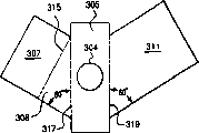
The particle that shows among Fig. 3 A, 3B and the 3C disperses assembly to pass through, for example, and the plane template manufacturing of flaky material shown in Figure 4.The yardstick of assembly and direction are unnecessary among Fig. 4 determines in proportion.Template comprises the trimmer 307 that is used for substrate 305, forms deflection plane 309, the trimmer 311 that forms dispersion face 313 and the part of triangle linkage section 308.On substrate 305, form hole 304.Particle disperses assembly to make through the following steps: be bent upwards trimmer 307 along dotted line 315, form with respect to the angle between one 30 to 60 degree of triangle linkage section 308; Be bent upwards triangle linkage section 308 along dotted line 317, form angle with respect to about 90 degree of substrate 305; Be bent upwards trimmer 311 along dotted line 319, form angle with respect to about 90 degree of substrate 305.In one embodiment, the angle that trimmer 307 and triangle linkage section are 308 is about 45 degree, and the angle that triangle linkage section 308 and substrate are 305 is about 90 degree, and the angle of 305 of trimmer 311 and substrates is about 90 degree.Fully crooked and form particle and disperse assembly after, the Plane intersects of the plane of trimmer 307 and trimmer 311 is in one about 30 to 60 angle of spending.
Based on the relative angle between the particle dispersion assembly of above-mentioned discussion, the axle of the conduit in numerous holes on any one hole site will be spent angles into about 20 to about 45 with the planar shaped of disperseing face.The angle (Fig. 3) of this angle dependence between trimmer 307 and triangle linkage section 308, this angle can change in 30 to 60 degree, and the angle (Fig. 4) between substrate 305 and triangle linkage section 308 outer side edges, and this angle can change in 20 to 45 degree.
When template was flat before forming particle dispersion assembly, the angle between substrate 305 and triangle linkage section 308 outer side edges, and the angle between substrate 305 and trimmer 311 sides can change at 45 to 70 degree.In Fig. 4 exemplary embodiments, this angle is 60 degree, and is determined by the angle of rotation loading arm and vertical direction, and it is 60 degree (for example, referring to Fig. 1) with vertical direction in this example.For example, when the specified angle of this angle of using the rotation loading arm and Fig. 4, hole 303 will be intersected with trimmer 307 in the projection of vertical direction.If need, can use other combination of the angle of the rotation angle of loading arm and Fig. 4 template.Optionally, can by triangle linkage section 308 is changed into part tiltedly rectangle with increase dotted line 315 to the hole 304 distance, increase from the hole by 304 vertical ranges to the face 309 of trimmer 307.
The yardstick and the angle of bend that use in making this typical particle dispersion assembly can change with shape, different aperture and the needs of different loading arm angles according to the different big or small of material in not departing from the scope of the present invention.In particle described herein disperseed range of needs, other shape and manufacture method were possible.For example, disperse to select to use plural trimmer in the assembly at a particle.In this selection, the trimmer 311 of Fig. 4 can be bent to form the trimmer that is positioned at trimmer 307 times and second angle reverse with it, and can connect the 3rd vertical trimmer in triangle linkage section 308 back.Then, the new trimmer deflection that the whereabouts particle can be adjusted sheet 307 successively and be come by trimmer 311 bendings, and by realizing final the dispersion with the new vertical trimmer that triangle linkage section 308 is connected later.
A plurality of dispersion trimmers can be whole or in part, is similar to typical template preparation shown in Figure 5 from one or more; The yardstick of assembly and direction are unnecessary in the figure determines in proportion.The typical template of Fig. 5 is designed for the dispersion trimmer that is provided for a plurality of holes, and wherein trimmer is alternately settled along a rotation loading arm direction with six holes.The dispersion trimmer 501 that is used for first, the 3rd and the 5th hole can form along dotted line 509 bendings by being similar to the mode that Fig. 4 discusses.The dispersion trimmer 505 that is used for second, the 4th and the 6th hole can pass through similar fashion, forms along dotted line 511 bendings.Can make the independent deflection trimmer (not shown) that is similar to trimmer 307 among Fig. 4, it oppositely is connected on each sheet that disperses trimmer 501 at side 515 places, and oppositely be connected in dispersion trimmer 505 at side 513 places.Then, final assembly can be connected on the conduit of rotation loading arm, and Fig. 4 is described as reference.
The hole disperses assembly preferably should settle at interval along each loading arm with relevant particle, so that the density of landing particle is even on container cross section.When the hole was equal sizes, this rule typically caused, and adjacent particle disperses the spacing of assembly to reduce with the radius distance increase from container center.Another is selected, and adjacent particle disperses the spacing of assembly to can be constant, and in the case, the size in hole should increase with the radius distance from container center.Can use the size and the adjacent particle in hole to disperse any combination of the spacing of assembly, as long as the density of landing particle is even on container cross section.
In the above-described embodiments, the hole can be arbitrary shape, but typically is circle or slotted eye.Another is selected, and the hole can be the hole of square, rectangle or any other shape.The smallest dimension of the qualification dimension definitions in a hole for causing particle to be built bridge.For example, the qualification of circular port is of a size of diameter, slotted eye be the length of minimum axle, square hole be the length of side, slot for minor face long, and tri-angle-holed be minimum constructive height.It is about 4 that the qualification size in hole and the ratio of average diameter of particles are preferably greater than, and can be about 4 to about 12 scopes.
Each rotation loading arm can be formed by the conduit of a segment length, and wherein conduit can be a pipe, with circular cross section and has the pipe of any required shape of cross section, pipeline or its combination that open on a top.The rotation loading arm is preferably self-load-bearing, but can comprise as required and increase solid support or supporter.Form the catheter shaft of each rotation loading arm, typically be oriented to and vertical extremely about 70 degree of about 45 degree that are.
The total flow resistance of particle that flows through a hole on the rotation loading arm should be bigger than the flow resistance that flows through conduit, so that an evenly distribution of the particle in hole is flow through in realization.Typically, total hole cross-sectional area should less than conduit cross section long-pending about 75%.The formed any burr of cutting hole should be eliminated on loading arm, flows through all holes to impel uniform particles.
Fig. 7 has shown another view of rotation loading arm 11, and it is the bottom view that obtains along perpendicular to the loading arm axle.The size of assembly and direction are unnecessary among Fig. 7 determines in proportion.Particle disperses assembly 601 to 611 can see by the view direction identical with Fig. 3 A.Fig. 7 has shown another selectable orientation that particle disperses assembly, and it can be used for minimizing the phase mutual interference from the grain flow of adjacent component whereabouts.Trimmer 629,615,631,633,635 and 637 is defined as deflection trimmer or face, and it alternately is placed in the both sides in hole on the pipe 11.Trimmer 602,613,621,623,625 and 627 is defined as disperseing trimmer or face, and it alternately is placed in the both sides in the hole on the pipe 11.Disperse the grain flow of assembly 601 through particle, for example, will be adjusted sheet 602 (in side view as seen) and be dispersed to a plane, this plane is relatively by the trimmer 613 of particle dispersion assembly 603 (in side view as seen) dispersed particles plane laterally offset.More uniform landing distribution of particles when this causes disperseing assembly 601 to 611 to be oriented to same direction than particle.Particle disperses the available geometry of this selectable orientation of assembly to be described as, plane and with the deflection plane of adjacent particle dispersion assembly tangent Plane intersects a angle in about 60 degree to about 90 degree tangent with the deflection plane of any particle dispersion assembly.
The particle of Fig. 7 disperses assembly to show, the directed trimmer 602,613,621,623,625 and 627 that disperses is parallel to the plane of loading arm axle usually so that trimmer is positioned at.Can use another selectable orientation, wherein the center line rotation particle around the hole disperses assembly, does not load the parallel plane of arm axle so that these trimmers are positioned in rotation.For example, the center line rotation particle around the hole disperses assembly, so that disperse trimmer to be positioned at the plane of loading arm axle perpendicular to rotation.All orientations are considered as this opinion inventive embodiment.
Fig. 8 has shown another embodiment of rotation loading arm, and it comprises the member that starts and stop to disperse from particle the grain flow of assembly.The yardstick of assembly and direction are unnecessary among Fig. 8 determines in proportion.In this embodiment, the rotation loading arm comprises first pipe 801, and it interrelates and second pipe 803 by grain flow and particle storage funnel (not shown), and it is coaxial and rotatably be placed in first and manage 801 end portion.Particle disperses assembly 805 to 815 to link to each other with second pipe 803 with the direction that replaces, and is similar to the particle dispersion assembly 601 to 611 of Fig. 6.Each has similar six holes of arranging to pipe in 801 and 803, when pipe is positioned at first or the position of opening, and these holes stacks or overlapping, as shown in Figure 8.When this position, particle can freely flow through interior pipe, and flows through overlapping hole to particle dispersion assembly 805 to 815.For stopping grain flow, manage 803 coaxial rotations, its mesopore is along circumferential backlash, sealed the hole of managing on 801 so that manage 803 inner arm.
Particle loads and can be undertaken by following manner: when pipe 803 is in the closed position, with the particle particle storage funnel of packing into; Swivelling pipe 803 is to open position and begin to rotate loading arm; Particle pack into container to required producing depth; Manage 803 to the closed position by moving then, and the loading arm that stops operating stops loading.
As above-mentioned particle flow control method is important because it allow to begin simultaneously porose grain flow, it is important for making homogeneous granules stream be settled down to formed bed face.Equally, this method allow to stop simultaneously porose grain flow, it is important for same reason.Another is not more preferably selected is to close grain flow in the upper end (being below cylindrical section 7 bottoms of Fig. 1) of the conduit that forms the rotation loading arm.This will not be uneven because of the last residual particles stream by the hole preferably more.
Although the foregoing description uses the plane trimmer to be used for deflection and dispersion face that particle disperses assembly, if need, these planes can be crooked or nonplanar.For example, can use recessed and protruding deflection and dispersion face, it can be embodiments of the invention.Although shown in trimmer have the rectangle section, trimmer can be Any shape, as long as can obtain suitable particle deflection and dispersion.
In the above-described embodiments, each particle disperses assembly to use two planes, and a deflection plane and a dispersion face are with distributed granule in loading process.Another can be selected among the embodiment in the present invention, and some or all of particles disperse assembly, and each can use only face, to simplify the structure of rotation loading arm.For example, can remove the trimmer 311 of Fig. 3 A, 3B and 3C, only stay trimmer 307 and come deflection and discrete particles.Perhaps, can imagine embodiment, wherein can use trimmer or face to come deflection and discrete particles greater than two.Scope of the present invention comprises that all these use one or more trimmer or face to come deflection and the dispersion train alternate embodiments through the particle in hole.
Fig. 9 has shown that the particle through one embodiment of the present of invention disperses, and it comprises that the particle of Fig. 6 disperses a zoomed-in view of assembly 603 and pipe 11.The yardstick of assembly and direction are unnecessary among Fig. 9 determines in proportion.Particle disperses assembly 603 to comprise trimmer 613, and its part is positioned at after trimmer 615 and the triangle linkage section 617 and the part of dispersion face 619, its in normal view as seen.The hole 604 of pipe 11 and 606 stacks of the hole of pipe 608 or congruence.Grain flow is crossed pipe 11 inside, through via hole 604 and 606, and from linkage section 617 rear portions, falls with vertical direction usually.Particles hit and flows through the space of 619 in trimmer 615 and dispersion face to the deflection plane at trimmer 615 back sides, they are deflected and form the grain flow of assembling 621 at there, and this grain flow finally strikes the dispersion face 619 of trimmer 613.Fan-shaped grain flow 623 shown in this is dispersed into aggregated particle stream 621.Pipe 11 is parts of a loading arm, and this arm has many particles and disperses assembly, and rotates in container as previously mentioned, thereby a large amount of fan-shaped grain flows that evenly fall are disseminated to particle layers surface (not shown).This distributing method has produced foregoing filling single-size bed.
Following example in detail the present invention, but do not limit the invention to any its described detail.
Embodiment
Use the particle shown in Fig. 3 A, 3B and the 3C to disperse assembly and grain flow Control Component shown in Figure 8, make one with similar particulate dispersion shown in Figure 2 system.The loading arm system comprises in two pipe (being similar to the interior pipe 801 of Fig. 8), and this Guan Youcong outer end to 304 stainless steels near 2.5 inches pipes of diameter of long 38 inches of the curved end of vessel axis numbers 10 make.An interior pipe has the hole of 15/32 inch of 9 diameter, and another has the hole of 15/32 inch of 10 diameter, and two are all discharged these holes in the bottom surface of arm along arm, so that the spacing in hole reduces with the radius distance from vessel axis, as shown in Figure 8.
According to template shown in the Figure 4 and 5, cut single deflection film down from 0.060 inch thick steel plate, and its particle that is bent to form shown in Fig. 3 A, 3B, 3C and 7 is disperseed assembly.These assemblies specifically are designed to be assemblied on the distribution arm with the vertical 60 degree modes that become.
Make 304 stainless steel tubes (being similar to the pipe 803 of Fig. 8) of 3 inches of two bigger outer end diameters pipe numbers 18, its have and above-mentioned in tubing like diameter, spacing and directed hole.Particle disperses assembly to use alternating direction shown in Figure 7, and zigzag is welded on the hole of more bassoon, and coaxial as shown in Figure 8 being placed in more on the tubule, to form complete loading arm.Loading arm is oriented to vertical and becomes 60 degree, and is designed to pack into and has in the container of 72 inches interior diameters.As following, container contains an annular bed.
The loading assembly as shown in Figure 2 that breaks away from loading arm is positioned at the top that is loaded container.Each rotation loading arm moves through support 15 and enters internal tank, and links to each other with bottom cylindrical section 207.Outer tube is rotatable, to open or close the hole on the pipe in the loading arm.
In this example, 3,775 pounds diameter 1.5mm LiNaKLSX absorbent particles is loaded into the annular space of container, and it has high 45.5 an inches bed, 7.75 inches annular space inner radial and 32.75 inches annular space outer radius.In this example, have two annular beds among single annular bed rather than Fig. 2.Container is equipped with inner coaxial cylindrical bed supporting clapboard or has the dividing plate 229 and the cylindrical bed supporting clapboard of outer, coaxial of 7.75 inches outer dias or have the dividing plate 227 of 32.75 inches inside diameters.In this embodiment, arm 215 is positioned on the length of 227 on the cylindrical bed supporting clapboard of inner bed supporting clapboard or dividing plate 229 and outer, coaxial or dividing plate along it, has particle and disperses assembly (be similar to particle and disperse assembly 223).Equally, arm 217 is positioned on the length of 227 on the cylindrical bed supporting clapboard of inner bed supporting clapboard or dividing plate 229 and outer, coaxial or dividing plate along it, has particle and disperses assembly (be similar to particle and disperse assembly 231).
From 55 gallons of drums particle hopper storage means 201 of packing into, this member comprises cylindrical funnel 203, truncated cone interlude 205 and the bottom cylindrical section 207 of Fig. 2 to particle at a predetermined velocity.In this example, do not use the inner dividing plate 213 that separates.With 1 rev/min of rotation that starts particle funnel/loading arm assembly, the hole of rotation outer tube interior pipe so that align in the hole, particle loads beginning.
Through behind 120 minutes loading operations, 3,775 pounds absorbent particles is loaded in the container altogether, and loads and finish.To rotate loading arm 215 and separate with bottom cylindrical section 207, and shift out container, then container preparation the carrying out operation of pressure oscillating adsorption process through support 15 with 217.
Claims (26)
1. the particle device of container of packing into, it comprises:
(a) particle hopper storage means;
(b) at least one comprises the rotation loading arm of a conduit, this conduit has first and second ends, wherein first end interrelates by grain flow and particle hopper storage means, and wherein a part of conduit has two or more holes, and these holes are between first end and second end;
(c) two or more particles disperse assembly, each particle disperses assembly to be spaced along described rotation loading arm, wherein each particle disperses assembly to comprise a deflection plane fixing with respect to the hole, so that the particle in the hole of flowing through can strike deflection plane and by its dispersion; With
(d) drive member is used to rotate at least one rotation loading arm.
2. device according to claim 1, it is characterized in that, each particle disperses assembly also to comprise a dispersion face, so that the projection in hole is not intersected with deflection plane, the angles of the tangent Plane intersects in any point in one 30 degree to 60 degree on tangent plane, any point and one and the dispersion face on one of them and the deflection plane, particle is deflected deflecting facet thus, strikes dispersion face, and is further disperseed by dispersion face.
3. device according to claim 2 is characterized in that deflection plane and dispersion face are the planes.
4. device according to claim 3 is characterized in that, the axle of the locational conduit of any one in two or more holes forms the angles of 20 to 45 degree with the plane of deflection plane.
5. device according to claim 3 is characterized in that, each deflection links to each other with the duct portion of dispersion face with the adjacent position, hole.
6. device according to claim 1 is characterized in that, catheter shaft is oriented to vertical direction and becomes 45 degree to 70 angles of spending.
7. device according to claim 1 is characterized in that, comprises two antipodal rotation loading arms.
8. device according to claim 1 is characterized in that, conduit is selected from the group that is made up of following material: pipe, pipe, pipeline and combination thereof.
9. device according to claim 1 is characterized in that, also comprises the control member that is used to control the rotary speed of rotating loading arm.
10. according to the device described in the claim 1, it is characterized in that, hopper storage means is a storage assembly, it comprises a hydrostatic column that links to each other with a truncated cone bottom stage, this truncated cone bottom stage is connected with a bottom cylindrical segment, and the rotation loading arm links to each other with the bottom cylindrical segment, so that drive member can be rotated rotation loading arm and storage assembly simultaneously.
The method of container 11. a particle is packed into, it comprises:
(a) provide a particle storage hopper that comprises particle;
(b) provide at least one rotation loading arm, it comprises a conduit with first end and second end, wherein the first end grain flow and particle storage hopper interrelate, and wherein the part of conduit has two or more holes, and these holes are between first end and second end;
(c) provide two or more particles to disperse assembly, each particle disperses assembly to be spaced along described rotation loading arm; Wherein each particle disperses assembly to comprise:
(1) deflection plane, the particle in the hole of flowing through thus can strike on the deflection plane and by its dispersion; With
The angles of the tangent Plane intersects in any point in one 30 degree to 60 degree on tangent plane, any point and one and the dispersion face on (2) dispersion faces, one of them and deflection plane;
(d) grain flow is crossed the rotation loading arm and is arrived the hole, the grain flow via hole, and particle is by under the vertical current of hole, and at least a portion particles hit is to deflection plane, and particle is deflected deflecting facet, and at least a portion deflection plane dispersed particles is further disperseed by dispersion face then; With
(e) rotate at least one rotation loading arm,, form particle layers therein to scatter the particle in the container.
12. method according to claim 11 is characterized in that, at least one rotation loading arm rotates around vessel axis.
13. method according to claim 11 is characterized in that, at least one rotation loading arm changes rotation with per minute 0.5 to 5.
14. method according to claim 11 is characterized in that, what and then particle layers loaded finishes, and the use vacuum removes a part of particle of bed face, with smooth bed face.
15. method according to claim 11 is characterized in that, what and then particle layers loaded finishes, and by manual sieving extra particle is dispersed to bed face.
16. the device of a control loading particle in container, it comprises:
(a) particle hopper storage means;
(b) at least one rotation loading arm, it comprises first section pipe with first end and second end, wherein first end interrelates by grain flow and particle hopper storage means, and wherein first section pipe has two or more holes, and these holes are between first end and second end;
(c) second section pipe, its internal diameter be greater than the external diameter of first section pipe, and wherein second section pipe is coaxial and be positioned at rotationally on first section pipe, and has two or more holes, wherein
(1) at first coaxial position, the hole on second section pipe is with respect to the hole orientation on first section pipe, so that particle can flow through paired hole overlapping on first and second sections pipes; With
(2) at second coaxial position, the hole on second section pipe is with respect to the hole orientation on first section pipe, so that the hole on first section pipe is by the sealing of the hole on second section pipe, so that particle can not flow through first section hole on the pipe;
(d) two or more particles disperse assemblies, and each particle disperses assembly to be connected in position on second section pipe adjacent with hole; With
(e) drive member is used for rotating the rotation loading arm, with particle in the dispersion cup.
17. device according to claim 16 is characterized in that, each particle disperses assembly to comprise:
(1) deflection plane, this deflection plane is fixed with respect to the hole, and the particle under the vertical current of hole can strike deflection plane and by its dispersion thus; With
(2) dispersion faces, the projection in hole do not intersect with deflection plane, one of them with deflection plane on tangent plane, any point and one and the dispersion face the tangent Plane intersects in any point spend greater than 30 and less than 60 angles of spending in one,
Thus, particle can be deflected face to be disperseed, and at least a portion is deflected the face dispersed particles and can strikes on the dispersion face, and is disperseed by dispersion face.
18. the method for particle is loaded in a control in container, it comprises:
(a) provide a particle storage hopper;
(b) provide at least one rotation loading arm, it comprises first section pipe with first end and second end, wherein first end interrelates by particle and particle storage hopper, and wherein first section pipe has two or more holes, and these holes are between first end and second end;
(c) provide second section pipe, its internal diameter is greater than the external diameter of first section pipe, and wherein second section pipe is coaxial and be positioned at rotationally on first section pipe, and has two or more holes, wherein
(1) at first coaxial position, the hole on the hole on second section pipe and the first section pipe is overlapping, so that particle can flow through paired hole overlapping on first and second sections pipes; With
(2) at second coaxial position, the hole on the first section pipe of Kong Buyu on second section pipe is overlapping, so that the hole on first section pipe is by the sealing of the hole on second section pipe, so that particle can not flow through first section hole on the pipe;
(d) provide two or more particles to disperse assembly, each particle disperses assembly to be connected in position on second section pipe adjacent with hole;
(e) first section and second section pipe are placed first coaxial position, start grain flow thus, the first section pipe of flowing through from the particle storage hopper, through the hole on first and second sections pipes, and through particle dispersion assembly, and rotate at least one rotation loading arm, the container of thus particle being packed into; With
(f) first section and second section pipe are placed second coaxial position, stop particle thus and flow into container.
19. method according to claim 18 is characterized in that, each particle disperses assembly to comprise:
(1) deflection plane is positioned at the adjacent position in hole, and wherein deflection plane is fixed with respect to the hole, and the particles hit under the vertical current of hole is to deflection plane thus, and the face that is deflected disperses; With
(2) dispersion faces, be positioned at the adjacent position in hole, on one of them and the deflection plane on tangent plane, any point and one and the dispersion face the tangent Plane intersects in any point in one greater than 30 degree and less than the angles of 60 degree, at least a portion is deflected the face dispersed particles and strikes on the dispersion face thus, and is disperseed by dispersion face.
20. one kind with pack into the device of container of particle, to form at least two annular beds that contain dissimilar particles, this device comprises:
(a) first particle hopper storage means comprises first type of particle;
(b) the funneling member of second particle comprises second type of particle;
(c) the first rotation loading arm comprises:
(1) has first run of first and second ends, wherein first end interrelates by the grain flow and first particle hopper storage means, and be positioned at the position of approaching vessel axis, wherein first run has two or more holes between the mid point of second end and first conduit, and wherein the mid point of first conduit is positioned at from one of vessel axis selected radius distance;
(2) two or more particles disperse assembly, and each particle disperses assembly to be spaced along the described first rotation loading arm on first run;
(d) the second rotation loading arm comprises:
(1) has second run of first and second ends, wherein first end interrelates by the grain flow and second particle hopper storage means, and be positioned at the position of approaching vessel axis, second run tool and two or more holes between the mid point of first end and second conduit wherein, and wherein the mid point of second conduit is positioned at from one of vessel axis selected radius distance; With
(2) two or more particle discrete particles assemblies, each particle disperse assembly to be spaced along the described second rotation loading arm on second run; With
(e) drive member is used for rotating the rotation loading arm, with discrete particles, forms first annular bed that contains first type of particle and the second annular bed that contains second type of particle in container.
21. device according to claim 20 is characterized in that, each particle disperses assembly to comprise:
(1) deflection plane, the particle under the vertical current of hole can strike on the deflection plane, and the face that is deflected disperses; With
(2) dispersion faces, one with deflection plane on the angles of the tangent Plane intersects in any point in one 30 degree to 60 degree on tangent plane, any point and and the dispersion face, at least a portion is deflected the face dispersed particles and can strikes on the dispersion face thus, and is disperseed by dispersion face.
22. device according to claim 20 is characterized in that, first and second catheter shafts are oriented to vertical and become 45 degree to 70 degree.
23. device according to claim 20 is characterized in that, the first and second rotation loading arms are antipodal.
24. device according to claim 20 is characterized in that, comprises that also an additional particle disperses member, be positioned on first conduit and the first conduit mid point position adjacent, and between the mid point and vessel axis of first conduit.
25. device according to claim 20 is characterized in that, comprises that also an additional particle disperses assembly, be positioned on second conduit and the second conduit mid point position adjacent, and between the mid point and container inner wall of second conduit.
26. a rotation loading arm is used for the particle container of packing into, it comprises:
(a) has one section conduit of first and second ends, wherein first end interrelates by grain flow and particle supply, and be positioned at the position of approaching vessel axis, wherein second end is positioned at the position of approaching container inner wall, and wherein conduit has two or more holes, and these holes are between first end, second end; With
(b) two or more particles disperse assembly, and each particle disperses assembly to be spaced along the described rotation loading arm on the run; Wherein each particle disperses assembly to comprise a deflection plane of settling with respect to the hole, disperses so that the particle under the vertical current of hole can be deflected face;
The angle that one of them and any particle disperse the tangent plane of the deflection plane of assembly and one and adjacent particle to disperse the tangent Plane intersects in 60 to 90 of deflection plane of assembly to spend.
Applications Claiming Priority (2)
| Application Number | Priority Date | Filing Date | Title |
|---|---|---|---|
| US10/215,463 US6866075B2 (en) | 2002-08-09 | 2002-08-09 | Method and apparatus for uniform particle loading of vessels |
| US10/215463 | 2002-08-09 |
Publications (2)
| Publication Number | Publication Date |
|---|---|
| CN1485258A CN1485258A (en) | 2004-03-31 |
| CN1283364C true CN1283364C (en) | 2006-11-08 |
Family
ID=30443741
Family Applications (1)
| Application Number | Title | Priority Date | Filing Date |
|---|---|---|---|
| CN03127565.6A Expired - Fee Related CN1283364C (en) | 2002-08-09 | 2003-08-08 | Method and apparatus for uniform particle loading of vessels |
Country Status (4)
| Country | Link |
|---|---|
| US (1) | US6866075B2 (en) |
| EP (1) | EP1388368A3 (en) |
| JP (1) | JP2004130304A (en) |
| CN (1) | CN1283364C (en) |
Families Citing this family (23)
| Publication number | Priority date | Publication date | Assignee | Title |
|---|---|---|---|---|
| US8155096B1 (en) | 2000-12-01 | 2012-04-10 | Ipr Licensing Inc. | Antenna control system and method |
| DE602007001938D1 (en) * | 2006-12-01 | 2009-09-24 | Haldor Topsoe As | Device for filling pipes with particulate catalytic material and filling method |
| GB2462797B (en) * | 2008-05-30 | 2012-08-08 | Catalyst Handling Res & Engineering Ltd | Particulate levelling system |
| US7762290B2 (en) * | 2008-11-06 | 2010-07-27 | Poet Research, Inc. | System for loading particulate matter into a transport container |
| WO2011050438A1 (en) * | 2009-10-30 | 2011-05-05 | Dean Jeffrey | Particulate material spreader |
| US20110271833A1 (en) * | 2010-05-05 | 2011-11-10 | Air Products And Chemicals, Inc. | Adsorbent Bed Support |
| CN102991733B (en) * | 2012-12-13 | 2014-10-22 | 清华大学 | Planetary particle material homogenizing mixed loading device |
| CN105276972A (en) * | 2014-07-01 | 2016-01-27 | 三久股份有限公司 | Scattering disk of material drying machine |
| EP3042716A1 (en) * | 2015-01-09 | 2016-07-13 | Haldor Topsøe A/S | Apparatus for loading a plurality of particulate catalytic material |
| CN104764742B (en) * | 2015-03-16 | 2017-11-17 | 周口师范学院 | The automatic dispersal device of cereal kernel of cereal parameter detecting case |
| CN107866906B (en) * | 2017-11-16 | 2019-05-10 | 重庆市瑞轩豪邦新型建材有限公司 | Dry-mixed mortar silo |
| EP3542894A1 (en) | 2018-03-22 | 2019-09-25 | Air Products And Chemicals, Inc. | Particle loading method and apparatus for a radial flow vessel |
| US10576455B2 (en) * | 2018-03-22 | 2020-03-03 | Air Products And Chemicals, Inc. | Particle loading method and apparatus for a radial flow vessel |
| CN108750153B (en) * | 2018-05-22 | 2020-05-26 | 温州大学瓯江学院 | Automatic bottling device for bearing balls |
| CN109987262B (en) * | 2019-03-08 | 2021-07-30 | 义乌市亚威机械设备有限公司 | Utilize centrifugation to get rid of plastic granules that falls with partial shipment device |
| KR102139144B1 (en) * | 2019-05-13 | 2020-07-29 | 박성근 | cake hopper with sliding gate |
| EP4103314A1 (en) * | 2020-02-12 | 2022-12-21 | CS Catalyst Services (Pty) Ltd | Device for handling catalyst and other material in a reactor vessel |
| JP7059315B2 (en) * | 2020-03-30 | 2022-04-25 | 本田技研工業株式会社 | Powder coating equipment and method |
| US11471818B2 (en) | 2020-06-24 | 2022-10-18 | Air Products And Chemicals, Inc. | Radial flow adsorption vessel with an integrated loading device |
| CN111871760B (en) * | 2020-07-07 | 2021-09-10 | 山东安和安全技术研究院有限公司 | Dust filtering device |
| US11596895B2 (en) | 2020-07-17 | 2023-03-07 | Air Products And Chemicals, Inc. | Radial adsorber, adsorption system, and adsorption methods |
| US20230027070A1 (en) | 2021-07-21 | 2023-01-26 | Air Products And Chemicals, Inc. | Air separation apparatus, adsorber, and method |
| US20230087673A1 (en) | 2021-09-23 | 2023-03-23 | Air Products And Chemicals, Inc. | Pre-purification arrangement for air separation and method of hybrid air purification |
Family Cites Families (21)
| Publication number | Priority date | Publication date | Assignee | Title |
|---|---|---|---|---|
| FR1299568A (en) | 1960-06-24 | 1962-07-27 | Centre Nat Rech Metall | Method and device for suspending solid carbonaceous materials in a carrier gas |
| US3265225A (en) * | 1964-03-27 | 1966-08-09 | Robert A Louks | Apparatus for level piling of granular material |
| US3285438A (en) | 1964-09-11 | 1966-11-15 | Bovay Engineers Inc | Particle storage bin |
| US3972686A (en) | 1974-01-31 | 1976-08-03 | Universal Oil Products Company | Device for loading catalyst particles into a reaction zone |
| US4040529A (en) * | 1976-05-17 | 1977-08-09 | Wurdeman Marion E | Grain flow propelled grain spreader |
| US4159785A (en) | 1976-06-01 | 1979-07-03 | Uop Inc. | Method for loading particulate matter in a vessel |
| US4162960A (en) * | 1978-03-29 | 1979-07-31 | Union Oil Company Of California | Shale retorting process and apparatus |
| US4239424A (en) * | 1979-07-25 | 1980-12-16 | Pullman Incorporated | Method and apparatus for distribution of granular material in a railway hopper car |
| US4300725A (en) | 1979-09-13 | 1981-11-17 | Moherek Edward F | Apparatus for uniformly dispensing and distributing material |
| JPS6118430A (en) | 1984-07-03 | 1986-01-27 | Idemitsu Kosan Co Ltd | Packing method of catalyst and packing apparatus of catalyst |
| US5296202A (en) * | 1984-12-07 | 1994-03-22 | Chevron Research And Technology Co. | Apparatus for uniformly loading particulate material into cylindrical beds |
| US5028007A (en) | 1989-08-31 | 1991-07-02 | Lavalley Industries, Inc. | Shower pipe assembly |
| US5324159A (en) | 1992-10-02 | 1994-06-28 | Praxair Technology, Inc. | Particle loader |
| DK171911B1 (en) | 1993-12-02 | 1997-08-11 | Topsoe Haldor As | Method and device for uniform filling of catalyst tubes |
| US5837021A (en) | 1994-12-09 | 1998-11-17 | L'air Liquide, Societe Anonyme Pour L'etude Et L'exploitation Des Procedes Georges Claude | Installation for the treatment of at least one fluid, by passage through two adjacent masses of material |
| US5836362A (en) | 1997-07-15 | 1998-11-17 | Praxair Technology, Inc. | Multiple adsorbent loading method and apparatus for a radial flow vessel |
| US5950694A (en) | 1998-03-04 | 1999-09-14 | Uop Llc | Apparatus for dispensing particulate material |
| US6082639A (en) | 1999-01-25 | 2000-07-04 | Certainteed Corporation | Apparatus for increasing the density of blown insulation materials |
| GB9922940D0 (en) | 1999-09-29 | 1999-12-01 | Ici Plc | Catalytic reactor |
| CN1344581A (en) | 2000-09-15 | 2002-04-17 | 普莱克斯技术有限公司 | Pressure oscillating adsorption using mixed adsorbent layer |
| US6892969B2 (en) | 2001-06-05 | 2005-05-17 | Oramac, Inc. | Pulp washing shower |
-
2002
- 2002-08-09 US US10/215,463 patent/US6866075B2/en not_active Expired - Fee Related
-
2003
- 2003-08-04 EP EP03016698A patent/EP1388368A3/en not_active Withdrawn
- 2003-08-08 CN CN03127565.6A patent/CN1283364C/en not_active Expired - Fee Related
- 2003-08-08 JP JP2003290157A patent/JP2004130304A/en active Pending
Also Published As
| Publication number | Publication date |
|---|---|
| EP1388368A2 (en) | 2004-02-11 |
| EP1388368A3 (en) | 2004-03-31 |
| US6866075B2 (en) | 2005-03-15 |
| US20040025966A1 (en) | 2004-02-12 |
| JP2004130304A (en) | 2004-04-30 |
| CN1485258A (en) | 2004-03-31 |
Similar Documents
| Publication | Publication Date | Title |
|---|---|---|
| CN1283364C (en) | Method and apparatus for uniform particle loading of vessels | |
| KR0180048B1 (en) | Particle loader | |
| CN1137751C (en) | Multiple adsorbent loading method and apparatus for radial flow vessel | |
| KR930002241B1 (en) | Method and apparatus for uniformly loading paticulate material into cylinderical beds | |
| CN1037830C (en) | Apparatus for filling bulk products into container | |
| CN1263792A (en) | Device for processing granular article | |
| CN1500545A (en) | Apparatus for treating a particulate material with a height adjustment device | |
| CN105080435B (en) | Multitube radial bed reactor | |
| JP5000532B2 (en) | Apparatus for dispensing at least one particulate material into a container, filling apparatus, and filling method using such apparatus | |
| RU2006139002A (en) | GRANULATION METHOD IN A PSEUDO-LIQUIDED LAYER AND AN APPROPRIATE GRANULATOR | |
| WO2018164652A1 (en) | Rotating vibrating melt prilling device | |
| CN101048234A (en) | Impact sprinkler drive system | |
| US6923389B2 (en) | Uniform grain spreader | |
| JP2003527961A (en) | Bottom element for equipment for processing particulate matter | |
| AU772425B2 (en) | Device for dispersing a divided solid material inside a receptacle | |
| CN103702750B (en) | For the treatment of the equipment of particulate material | |
| CN1123377C (en) | Crossing tray for structural members in space of tower and tube | |
| KR100463759B1 (en) | Apparatus for continuous spheronisation | |
| JPH0644987B2 (en) | Catalyst filling device | |
| CN114682170B (en) | Catalyst filling device and filling method | |
| RU2236776C2 (en) | Method and apparatus for surface application of bulk materials | |
| CN114653595B (en) | Pharmacy production capsule screening plant | |
| JPH10296069A (en) | Granulating device | |
| JP6412973B2 (en) | Particulate spraying device and spraying method | |
| JPS6255831B2 (en) |
Legal Events
| Date | Code | Title | Description |
|---|---|---|---|
| C06 | Publication | ||
| PB01 | Publication | ||
| C10 | Entry into substantive examination | ||
| SE01 | Entry into force of request for substantive examination | ||
| C14 | Grant of patent or utility model | ||
| GR01 | Patent grant | ||
| C17 | Cessation of patent right | ||
| CF01 | Termination of patent right due to non-payment of annual fee |
Granted publication date: 20061108 |