CN1280809C - Magnetic tape recording/reproducing device - Google Patents
Magnetic tape recording/reproducing device Download PDFInfo
- Publication number
- CN1280809C CN1280809C CNB998005533A CN99800553A CN1280809C CN 1280809 C CN1280809 C CN 1280809C CN B998005533 A CNB998005533 A CN B998005533A CN 99800553 A CN99800553 A CN 99800553A CN 1280809 C CN1280809 C CN 1280809C
- Authority
- CN
- China
- Prior art keywords
- tape
- arrow
- mentioned
- magnetic head
- gear
- Prior art date
- Legal status (The legal status is an assumption and is not a legal conclusion. Google has not performed a legal analysis and makes no representation as to the accuracy of the status listed.)
- Expired - Fee Related
Links
Images


Classifications
-
- G—PHYSICS
- G11—INFORMATION STORAGE
- G11B—INFORMATION STORAGE BASED ON RELATIVE MOVEMENT BETWEEN RECORD CARRIER AND TRANSDUCER
- G11B15/00—Driving, starting or stopping record carriers of filamentary or web form; Driving both such record carriers and heads; Guiding such record carriers or containers therefor; Control thereof; Control of operating function
- G11B15/18—Driving; Starting; Stopping; Arrangements for control or regulation thereof
- G11B15/1883—Driving; Starting; Stopping; Arrangements for control or regulation thereof for record carriers inside containers
-
- G—PHYSICS
- G11—INFORMATION STORAGE
- G11B—INFORMATION STORAGE BASED ON RELATIVE MOVEMENT BETWEEN RECORD CARRIER AND TRANSDUCER
- G11B15/00—Driving, starting or stopping record carriers of filamentary or web form; Driving both such record carriers and heads; Guiding such record carriers or containers therefor; Control thereof; Control of operating function
- G11B15/18—Driving; Starting; Stopping; Arrangements for control or regulation thereof
- G11B15/44—Speed-changing arrangements; Reversing arrangements; Drive transfer means therefor
- G11B15/442—Control thereof
-
- G—PHYSICS
- G11—INFORMATION STORAGE
- G11B—INFORMATION STORAGE BASED ON RELATIVE MOVEMENT BETWEEN RECORD CARRIER AND TRANSDUCER
- G11B15/00—Driving, starting or stopping record carriers of filamentary or web form; Driving both such record carriers and heads; Guiding such record carriers or containers therefor; Control thereof; Control of operating function
- G11B15/60—Guiding record carrier
- G11B15/66—Threading; Loading; Automatic self-loading
- G11B15/665—Threading; Loading; Automatic self-loading by extracting loop of record carrier from container
- G11B15/6651—Threading; Loading; Automatic self-loading by extracting loop of record carrier from container to pull the record carrier against non rotating heads
-
- G—PHYSICS
- G11—INFORMATION STORAGE
- G11B—INFORMATION STORAGE BASED ON RELATIVE MOVEMENT BETWEEN RECORD CARRIER AND TRANSDUCER
- G11B5/00—Recording by magnetisation or demagnetisation of a record carrier; Reproducing by magnetic means; Record carriers therefor
- G11B5/48—Disposition or mounting of heads or head supports relative to record carriers ; arrangements of heads, e.g. for scanning the record carrier to increase the relative speed
- G11B5/54—Disposition or mounting of heads or head supports relative to record carriers ; arrangements of heads, e.g. for scanning the record carrier to increase the relative speed with provision for moving the head into or out of its operative position or across tracks
Landscapes
- Toys (AREA)
- Casings For Electric Apparatus (AREA)
- Feeding And Guiding Record Carriers (AREA)
Abstract
A recording and/or reproducing apparatus using a magnetic tape as a recording medium such that, when holding by a holding mechanism is released at the position where a cover member is closed and a magnetic head is moved between a contact position, where contact with a magnetic tape which travels by a traveling mechanism provided in the apparatus body is obtained, to a position distant from the magnetic tape or when the magnetic tape is pinched by the traveling mechanism, the pinching of the magnetic tape by the traveling mechanism is released and the magnetic head is moved to a distant position. In this manner, even if the apparatus is stopped when the power source is shut off while the FWD reproducing mode or the REV reproducing mode is kept set, the magnetic tape can be safely and securely extracted from the attachment section.
Description
Technical field
The present invention relates to a kind of record and playing device that adopts tape as recording medium, as magnetic tape type sound-track engraving apparatus etc., particularly relate to and a kind ofly not only removed the walking states of tape but also made magnetic head and device that tape is separated after the closed condition that will be located at the lid on the device body is removed, wherein lid is used for tape closed in it and is adorning part.
Background technology
In the prior art, adopt the tape that is contained in the tape cassete as recording medium usually, and adopt record and/or the playing device of cassette tape recorder as tape.This blattnerphone has following four kinds of pattern: FWD (forward) play mode, REV (oppositely) play mode, FF (F.F.) pattern and REW (rewinding) pattern.Under the FWD play mode, tape is just being changed one's profession away along the 1st direction of travel with certain speed and is being play the information signal that is writing down on the tape simultaneously, wherein the 1st direction of travel is meant the direction of reeling to another tape volume from tape volume, and two tape volumes are bearing in two one side of something of tape cassete respectively and can freely rotate.Under the REV play mode, tape is play the information signal that is writing down on the tape with certain speed simultaneously along the 2nd direction of travel counter-rotating walking, and wherein the 2nd direction of travel is meant the direction of reeling to previous tape volume from back tape volume.Under the FF pattern, tape is rolled up a side with the tape of just changing one's profession away at a high speed backward and is carried out high-speed winding (F.F.).Under the REW pattern, tape is rolled up a side with the high speed reverse rotation walking to previous tape and is carried out high speed warp (rewinding).These several operator schemes are selected by tape transport mechanism is carried out blocked operation, and this tape transport mechanism comprises the mechanisms such as tape travel mechanism that are made of various gears and lever etc.
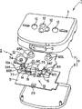
Be used to switch the tape transport mechanism employing structure as shown in figs. 1 and 2 of the various operator schemes of selecting blattnerphone.
As illustrated in fig. 1 and 2, the cam mechanism 201 on this tape transport mechanism is bearing on the chassis of blattnerphone, and drives rotation by not shown CD-ROM drive motor.Form effigurate convex row race 202 on the principal plane of this cam mechanism 201.
The mode switch bar 203 that can move along arrow X1 among Fig. 1 and Fig. 2 and X2 direction is installed on the chassis.This mode switch bar 203 fastens by engaging protrusion on the one end 204 and cam path 202, be accompanied by the rotation of cam mechanism 201, clamped position between cam path 202 and the engaging protrusion 204 changes, thereby it can be moved along arrow X1 among Fig. 1 and Fig. 2 and X2 direction.Mode switch bar 203 stops at the selection that realizes various operator schemes on the chosen position of the FWD play mode, FF pattern, REW pattern and the FEV pattern that are located on the cam path 202 respectively by the engaging protrusion on it 204.Middle part one side of mode switch bar 203 is provided with a service portion 205 that is used to rotate the aftermentioned dwang.
Magnetic head mounting base 206 is supported on the chassis of blattnerphone, be used for the unshowned magnetic head of installation diagram, and can move along the direction shown in arrow Y1 and the Y2 among Fig. 1 and Fig. 2, this both direction is vertical with mode switch bar 203, is that magnetic head mounting base 206 contacts and the direction of separating with the tape of cassette tape recorder.This tape is contained on the not shown tape mounting portion of blattnerphone.Formed an operating sheet 207 that is used to make dwang 208 rotations at the middle part of magnetic head base 206.In addition, the arrow Y2 direction in Fig. 1 and Fig. 2 depends on by not shown spring member for tape pedestal 206.
The chassis is provided with dwang 208, and this dwang is a rotating fulcrum with the position of therefrom mind-set one distolateral displacement.The pressing operation sheet 209 that is used to push the operating sheet 207 on the magnetic head base 206 is housed on the other end of this dwang 208.And, also be provided with retroaction projection 210 on this dwang 208, relative with the service portion that is concavity 205 that is provided with on the mode switch bar 203.
As above the tape transport mechanism of Gou Chenging is as follows at the state under the REW pattern: mode switch bar 203 is arranged on the middle position of the moving range shown in Fig. 1 and Fig. 2 arrow X1 and the X2 direction, and move the end of magnetic head base 206 arrow Y2 direction in the moving range shown in arrow Y1 and the Y2 direction in Fig. 1 and Fig. 2.Under this state, be installed on the position that magnetic head is in tape separates on the magnetic head base 206, do not contact with tape.This moment be located on the magnetic head base 206 operating sheet 207 as shown in Figure 1, contact with the pressing operation sheet 209 of dwang 2 08.
Tape transport mechanism makes mode switch bar 203 move along arrow X2 direction among Fig. 2 by its cam mechanism 201 rotations, thereby presents state shown in Figure 1 under state shown in Figure 2, promptly for example selected the REW pattern.Under the state after having selected the REW pattern, as make mode switch bar 203 move along arrow X2 direction among Fig. 2, the retroaction projection 210 of dwang 208 and the service portion 205 of mode switch bar 203 are fastened, and are that rotate along the clockwise direction among Fig. 1 at the center thereby make service portion 205 with the fulcrum 208a of dwang 208.
Dwang 208 rotates along the clockwise direction among Fig. 1 and makes operating sheet 207 operating sheet 209 that is pressed push, and magnetic head base 206 direction shown in the arrow Y1 in Fig. 1 is moved.Magnetic head base 206 direction shown in the arrow Y1 in Fig. 1 moves, and makes magnetic head that is installed on this magnetic head base 206 and the tape sliding contact of walking with certain speed, thereby forms the state that the information signal that is recorded on the tape can be play.
In the blattnerphone that utilizes driving power to drive to make the tape transport mechanism action, tape is activated with certain speed and walks, this moment, magnetic head contacted slidably with this tape, and make the pairing information signal of magnetic head be recorded or play, if power cut-off then magnetic head still remain on and the contacted state of tape in this process.Therefore, under the situation that in the process of record or broadcast, takes place to want tape is taken out from blattnerphone behind the power cut-off, energized allows tape transport mechanism move once more, and makes magnetic head leave and could realize from tape, thereby the operability of sound-track engraving apparatus is poor.
Portable blattnerphone is owing to adopt battery as driving power, thereby under the situation of running down of battery, as the battery that does not more renew its tape transport mechanism moved.In addition, no matter be portable or in the record and/or playing device of desk-top employing tape, all the reason that the tape that occurs in record or playing process might be stopped to walk thinks it is that device breaks down rather than power cut-off by mistake, and the phenomenon that the user takes out tape forcibly owing to the contact condition that can not remove magnetic head and tape all might occur.Like this,, the danger of damage tape is arranged not only from sound-track engraving apparatus, but also have damage to be installed in record and/or the tape travel mechanism of playing device side and the danger of magnetic head if under the state of magnetic head and contact with tape, tape is taken out.
Therefore, even people wish also need not reclose when tape stops to walk under the state of magnetic head and contact with tape power supply magnetic head is separated with tape, thereby tape is taken out from sound-track engraving apparatus.
Above-mentioned tape transport mechanism, under magnetic head and the contacted state of tape, the engaging protrusion 204 of mode switch bar 203 fastens with the cam path 202 of cam mechanism 201, the service portion 205 of mode switch bar 203 fastens with the retroaction projection 210 of dwang 208, the pressing operation sheet 209 of dwang 208 forces together with the operating sheet 207 of magnetic head base 206, thereby makes that cam mechanism 201, mode switch bar 203, dwang 208 and magnetic head 206 all can not single movements.
Thus, in tape transport mechanism illustrated in figures 1 and 2, magnetic head and the tape sliding contact of walking with certain speed are play the information signal that is recorded on the tape or recorded information on tape.When making tape stop to walk,, cam mechanism 201 is rotated, the direction of magnetic head base 206 arrow Y2 in Fig. 1 and Fig. 2 is moved so that magnetic head leaves tape for tape is taken out when power cut-off in the said process.
Like this, when each member that constitutes tape transport mechanism is mechanically moved, must there be enough big power to overcome the friction force of each member and makes the power of spring member that magnetic head depends on to tape one side etc. that each member is moved.At this moment, in order to make this bigger power each member is sustained damage, nor remove the connection status between each member, just must improve the intensity of each member, or adopt the high part of permanance, thereby cause the rising of manufacturing cost.
Disclosure of an invention
The record and/or the playing device that the purpose of this invention is to provide a kind of tape; in the time will being contained in adorning locational tape and take off in the device body from adorning the position; this device can make magnetic head leave from tape; remove the tape travel mechanism simultaneously to the seizing on both sides by the arms of tape, and protection tape or be contained in each mechanism on record and/or playing device one side.
Another object of the present invention provides a kind of record and/or playing device of tape, this device carries out in the process of the record of information signal or broadcast in the magnetic head and the tape sliding contact of walking, even when tape stops to walk, magnetic head is left from tape, remove the tape travel mechanism simultaneously to the seizing on both sides by the arms of tape, thereby tape can be taken off from the position of adorning in the device body.
Another object of the present invention provides a kind of record and/or playing device of tape, this device makes magnetic head leave from tape when being used to cover the lid of adorning tape segment opening, remove the tape travel mechanism simultaneously to the seizing on both sides by the arms of tape, thereby tape can be taken off from the position of adorning in the device body.
Another object of the present invention provides a kind of record and/or playing device of tape, even carry out under the situation of power cut-off in the process of the record of information signal or broadcast in magnetic head and the tape sliding contact in the walking, this device need not once more energized can make magnetic head leave from tape, remove the tape travel mechanism simultaneously to the seizing on both sides by the arms of tape, thereby tape can be taken off from the position of adorning in the device body.
In order to realize above-mentioned purpose of the present invention, the record and/or the playing device of tape of the present invention comprise: the device body that tape is installed; Be located at the lid on this device body freely openable, be used for adorning on the opening and closing device body part of adorning of tape; This lid is remained on the locational maintaining body that the part of tape is installed in the stopping device body; Be located at the maintaining body on this device body, the travel mechanism that is used to seize tape on both sides by the arms and this tape is walked under the quilt state of seizing on both sides by the arms; Be contained in the magnetic head on the device body, drive by travel mechanism the contacted contact position of tape walking and with position that tape separates between move; Switching mechanism, be used to remove the maintenance of maintaining body to the lid off-position, and releasing travel mechanism seizing on both sides by the arms to tape, magnetic head is moved on the position of leaving tape, and this lid is to be maintained on the off-position under the state of this magnetic head and the contacted contact position of tape or under the state of magnetic head being seized on both sides by the arms by travel mechanism.
The record of tape of the present invention and/or playing device also comprise the releasing operating portion, are used to remove the maintenance of maintaining body to lid.And, remove operating portion by operation, switching mechanism is removed the seize state of travel mechanism to tape, make simultaneously magnetic head to position that tape separates on move.
The record of tape of the present invention and/or playing device also comprise a plurality of operating portions, be used for by the tape walking states of travel mechanism control and realize the record of tape by magnetic head or the state of broadcast between switch.In addition, switching mechanism also can make magnetic head move to contact position or separation point position by any operating portion in a plurality of operating portions of operation, simultaneously travel mechanism is switched to the state of seizing tape on both sides by the arms.
The record of tape of the present invention and/or playing device also comprise a motor that starts by the operation of operating portion.Switching mechanism also comprises the mode switch bar that moves by the drive of motor driven power, by this mode switch bar control head and travel mechanism.
This travel mechanism comprises a capstan and a belt hold roller at least, and both together seize tape on both sides by the arms and make the tape walking, and this switching mechanism is removed belt hold roller and capstan to the state of seizing on both sides by the arms of tape when operating portion is removed in operation.This switching mechanism comprises the 1st move operation portion and the 2nd move operation portion, the former by the mode switch bar make magnetic head with contact with tape and the position of separating between move, the latter makes belt hold roller move to together seizing on both sides by the arms on the position of tape with capstan.
In addition, the record of tape of the present invention and/or playing device also comprise detector switch and driving mechanism, detector switch is used to detect the position of a pair of tape volume platform and mode switch bar, and driving mechanism is used for utilizing a pair of tape volume of the drive force of motor platform any, the rotation direction of coming switching motor according to the detected result of detector switch, thus switch tape platform by drive mechanism.
The concrete benefit of other purpose of the present invention and employing gained of the present invention will become clearer by following explanation to embodiment.
Brief description of drawings
Fig. 1 is the vertical view that is used for the tape transport mechanism part of blattnerphone of the prior art, shows the mode switch bar and moves state before.
Fig. 2 is the vertical view that the mode switch bar moves the back state.
Fig. 3 is the stereographic map of tape player of the present invention.
Fig. 4 is the stereographic map under the above-mentioned tape player lid open mode.
Fig. 5 is the exploded perspective view of above-mentioned tape player of the present invention.
Fig. 6 is the front view of the state lower cover locking mechanism before lid is locked.
Fig. 7 is the front view of the state lower cover locking mechanism after lid is locked.
Fig. 8 is the enlarged front view of the state lower cover locking mechanism after the locking of lid has just been removed.
Fig. 9 is the vertical view of tape transport mechanism when selecting the FWD play mode.
Figure 10 is the vertical view of tape transport mechanism when selecting the FF pattern.
Figure 11 is the vertical view of tape transport mechanism when selecting the REW pattern.
Figure 12 is the vertical view of tape transport mechanism when selecting the REV play mode.
Figure 13 is the vertical view that transmits gear and cam mechanism engagement.
Figure 14 is the vertical view that transmits gear and clutch gear engagement.
Figure 15 is the cut-open view that constitutes the clutch gear of tape player of the present invention.
Figure 16 illustrates the disc spring of clutch gear and the stereographic map of axial region position relation.
Figure 17 is the vertical view that is illustrated in the relation of the position between the cam mechanism and slide protrusion under the various operator schemes.
Figure 18 is the view of the engagement of translating gear and clutch gear, and this figure is be meshed with the clutch gear stereographic map of state of the small diameter gear part of expression translating gear.
Figure 19 is be meshed with the clutch gear stereographic map of state of the gear wheel in large diameter part of expression translating gear.
Figure 20 is the vertical view that actuating strut and locking pedestal are shown.
Figure 21 is the vertical view that magnetic head base and glide base are shown.
Figure 22 is Figure 21 cuts gained open along the XXII-XXII line a cut-open view.
Figure 23 is Figure 22 cuts gained open along the XXIII-XXIII line a cut-open view.
Figure 24 is the view of expression torsion disc spring effect, is the vertical view that the state after the locking pedestal moves is shown.
Figure 25 illustrates the vertical view that magnetic head base moves the back state.
Figure 26 to 30 is used for illustrating the course of action of the contact condition between locking pedestal compulsory commutation magnetic head and the tape.
Figure 26 is the vertical view that is set at FWD play mode state.
Figure 27 is the vertical view by the state of locking pedestal after with its compulsory commutation when being set at the FWD play mode.
Figure 28 is the vertical view that is set at REV play mode state.
Figure 29 is the vertical view by the state of locking pedestal after with its compulsory commutation when being set at the REV play mode.
Figure 30 is set under the REV play mode state, by the locking pedestal with its compulsory commutation after the vertical view of state of each member reposition postpone.
The best mode that carries out an invention
Specific embodiment to magnetic recording of the present invention and/or playing device describes with reference to the accompanying drawings.
Embodiment shown below is applicable to portable cassette player, this player has automatic turn-over playing function, so-called turn-over playing function automatically is meant can carry out ordinary playing and counter-rotating broadcast continuously, ordinary playing is the method for instigating tape the information signal that is writing down on the tape to be played back with the certain speed walking along working direction, and the counter-rotating broadcast is the method for instigating tape the information signal that is writing down on the tape to be played back with the certain speed walking along reverse directions.
As shown in Figure 3, tape player 1 of the present invention comprises body 2 and is used to open and close the lid 3 of this body 2, as shown in Figure 4, on body 2, be provided with installation portion 6, be used to adorning the magnetic tape cassette 5 that accommodates tape 4, as shown in Figure 5, body 2 comprises a casing 9, is made up of the last half side engine housing 7 of frame shape and the following half side engine housing of installing thereunder.Dispose chassis 10 and printed circuit board (PCB) 11 in this casing 9, chassis 10 is positioned at the top of circuit board 11, and the various members of formation tape player 1 portion of mechanism etc. are installed on it.
The end rotation that switching is located at the lid 3 of the portion that adorning 6 on the body 2 is bearing on the half side casing 7 freely, as shown in Figure 4, has formed the holding section 3a of the outstanding font of falling L below its leading section.Rotate to the direction of closing body 2 upper surfaces (calling " closing direction " in the following text) by lid 3, the locking component of holding section 3a and locking mechanism described later fastens and is locked on the off-position, engaging between holding section 3a and the locking component is rotated to the direction of opening body 2 upper surfaces (calling " opening direction " in the following text) after removing.As shown in Figure 3 and Figure 4, dispose a plurality of model selection buttons 12 and volume operating knob at the upper surface of lid 3, the former is used to be embodied as the operator scheme of selecting tape player 1 and the mode selection switch blocked operation that carries out, and the latter is used to regulate volume.Tape player 1 of the present invention is selected button 12 by operator scheme, make the tape 4 be contained in the magnetic tape cassette 5 walk with certain speed, be chosen in the various operator schemes such as F.F., counter-rotating of broadcast information signal on this tape 4 or tape 4 along working direction or reverse directions.
As shown in Figure 3 and Figure 4, open knob 13 and be bearing on the front of the last half side engine housing 7 that constitutes body 2, can move freely, be used to remove lock-out state lid 3.Open knob 13 and come engaging between 3a of engagement release portion and the locking component by the slide to the left and right directions shown in Fig. 3, as shown in Figure 4, lid 3 is in the state that can rotate along the direction that the portion that adorning 6 on body 2 upper surfaces one side that is located at is opened.As shown in Figure 4, on the side of the front of last half side casing 7, be formed with notch 7a, be used to make the part of locking mechanism to embed wherein.
As shown in Figure 5, be installed in the leading section lateralization bending on the chassis 10 in the body 2 and form installation portion 14.This installation portion 14 is provided with locking mechanism 15, is used for lid 3 is locked in off-position.As shown in Figure 6, be formed with spring hanging hole 14b on this installation portion 14 and roughly also be equipped with inserting hole 14a on the position intermediate at it, above-mentioned spring hanging hole 14b is used for an end of the crank spring 17 that constitutes locking mechanism 15 is fixed.
Shown in Fig. 6 to 8, the locking mechanism 15 that is supported on the installation portion 14 is made of locking component 16, crank spring 17 and link piece 18, and crank spring 17 is used for applying rotating force to this locking component 16, and link piece 18 is used for linking unlatching knob 13 and locking component 16.
As shown in Figure 6, locking component 16 by supporting slice 19 and from this supporting slice 19 to figure the outstanding locking plate 20 in top integrally formed.Be formed with connect apertures 21 and the 1st support holes 22 in Fig. 6 of supporting slice 19 on the part of left one side respectively, the two is arranged in along on the position that the figure left and right directions separates up and down.In Fig. 6 of locking component 16, be formed with the 2nd support holes 23 on the part of a right-hand side.The 2nd support holes 23 on right side comprises: part 1 23a and part 2 23b, form a L font roughly, wherein part 1 is extended longlyer along the left and right directions among Fig. 6 of supporting slice 19, and part 2 is extended shortlyer from this part 1 23a right part among Fig. 6 below slightly.As shown in Figure 6, there is roughly L shaped holding section 20a outstanding on the upper end of locking plate 20 left parts, also is formed with than holding section 20a more to the outstanding rotating operation sheet 20b in side to the side.In addition, in Fig. 6 of locking plate 20, also upwards be formed with the 20c of spring suspension portion that is circular on the bottom of right part with erecting.The following ora terminalis of the left part of supporting slice 19 is as the operating portion 20d of operation aftermentioned detector switch.
As shown in Figure 6, link piece 18 is extended along the length direction of installation portion 14, is made of support 24 and linking part 25, and the top of linking part 25 right part from Fig. 6 of this support 24 is upwards given prominence to shortly and extended more longways to right-hand.Be formed with a pair of support holes 24a, 24a on the support 24 of link piece 18, and roughly be formed with rearward outstanding pressing tablet 24b on the centre position, above-mentioned a pair of support holes is separated on the left and right directions in Fig. 6, and the length direction of installation portion 14 is a major diameter.In Fig. 6 of linking part 25, be formed with the 1st forwards outstanding binding projection 25a on the upper end of right part, on the bottom of its right part, be formed with the 2nd rearward outstanding binding projection 25b.
As shown in Figure 6, locking component 16 is supported by inserting fulcrum post 26,27 respectively in the 1st and the 2nd support holes 22,23, and can in the scope of the 1st and the 2nd support holes 22,23, on installation portion 14, move, above-mentioned fulcrum post 26,27 is upwards holded up from being located on the installation portion 14 on the chassis 10.In addition, link piece 18 is supported by inserting fulcrum post 28,28 in support holes 24a, the 24a respectively, and can move at installation portion 14 upper edge left and right directions in the scope of support holes 24a, 24a, and above-mentioned fulcrum post 28,28 is upwards holded up from installation portion 14.This locking component 16 bears the elastic force that is installed in the 20c of spring suspension portion and is formed at the crank spring 17 between the spring suspension hole 14b on the installation portion 14, with fulcrum post 26,27 is the center, rotate displacement along arrow R1 direction among Fig. 6 or arrow R2 direction, this fulcrum post 26,27 and the 1st and the 2nd support holes 22,23 fasten.
Locking pedestal described later by compressing tablet with to be inserted in the pressing tablet 24b of the link piece 18 in the inserting hole 14a adjacent, and be supported on the bottom surface on chassis 10, link piece 18 is when arrow S2 direction moves to Fig. 7 from the position shown in Fig. 6, be subjected to pressing tablet 24b applied pressure by compressing tablet, make the locking pedestal with moving direction Fig. 6 in the same way of link piece 18 in arrow S2 direction move.
As shown in Figure 5, detector switch 29 is configured in the leading section that is installed on the printed circuit board (PCB) 11 in the device body 2.This detector switch 29 is used to detect the on off state of lid 3, make detector switch 29 be the ON state, then this device is in can provide the state of electric current to motor from not shown power supply, makes detector switch 29 be the OFF state, and then this device is in the state that stops to provide to motor electric current.This detector switch 29 is located at and can be undertaken on the position of pressing operation by the operating portion 20d of the locking component 16 that to be the center with fulcrum post 26,27 joltily rotate along the arrow R1 direction among Fig. 6 to 8 or R2 direction.
When lid 3 turns to the open position of the portion that adorning 6 that is located at the magnetic tape cassette 5 on the device body 2 shown in Fig. 4, as shown in Figure 6, fulcrum post 26,27 lays respectively at the lower end of the part 2 23b of the 1st support holes 22 right-hand members of locking component 16 and the 2nd support holes 23, locking component 16 rotates along arrow R2 direction among Fig. 6, drives the top that locking plate 20 moves to chassis 10 among Fig. 6.At this moment, as shown in Figure 6, locking component 16 is applied with by crank spring 17 at the spring suspension sheet 20c of locking plate 20 under the state of the power that in Fig. 6 arrow R2 direction rotates locking component 16 is remained on the non-locked position, on this position be located at lid 3 on holding section 3a between engage and be disengaged.
When locking component 16 is in non-locked position shown in Fig. 6, effect arrow S1 direction in Fig. 6 that link piece 18 is subjected to the elastic force of spring member moves, fulcrum post 28,28 contacts with support holes 24a, 24a left end place in Fig. 6, thereby the shift position of this fulcrum post is restricted.At this moment, as shown in Figure 6, the 2nd of link piece 18 links the right part of projection 25b in the connect apertures 21 of locking component 16 and contacts with it.In case the detector switch 29 that is configured on the printed circuit board (PCB) 11 is operating as the OFF state by the operating portion 20d of locking component 16, promptly stops motor being powered.
When lid 3 makes state that the portion of adorning 6 opens when the direction that the portion of adorning 6 is closed is rotated from shown in Figure 4, be located on the lid 3 holding section 3a along Fig. 6 arrow A 1 direction with the rotating operation sheet 20b of locking component 16 to the approaching direction in chassis 10 by rolling over.As holding section 3a when arrow A 1 direction is pushed in Fig. 6 with rotating operation sheet 20b, locking component 16 is that rotating fulcrum arrow R1 direction in Fig. 6 is rotated with fulcrum post 26.At this moment, crank spring 17 with the spring suspension hole 14b of installation portion 14 in the part that engages be rotating fulcrum, clockwise rotate along arrow R3 among Fig. 6.When locking component 16 arrow R1 direction in Fig. 6 turns over a predetermined angle, crank spring 17 is crossed the dead point at this place, and drive locking component 16 by its spring force and be rotated further along arrow R1 direction among Fig. 6, give the 1st and the 2nd support holes 22,23 guiding by fulcrum post 26,27 simultaneously, it is moved along 1 direction of arrow C among Fig. 7, as shown in Figure 7, the holding section 3a of lid 3 is maintained on lid 3 latched positions that fasten with holding section 20a.That is to say that the fulcrum post 26 that locking component 16 will be located at installation portion 14 1 sides is positioned on the position of the 2nd support holes 22 left end side, and fulcrum post 27 is positioned on the left end side position of the 2nd support holes 23 part 1 23a.So, by locking component 16 in Fig. 7 the clockwise rotation of arrow R1 direction and in Fig. 7 the moving of arrow C 1 direction, holding section 3a on holding section 20a and the lid 3 is fastened, as shown in Figure 3, thus lid 3 is locked on the position of closing the portion that adorning 6 that the end face by body 2 constitutes.At this moment, locking component 16 is driven along the direction of arrow C among Fig. 71 by crank spring 17 and moves right, and has removed the pressed state of operating portion 20d to detector switch 29, makes detector switch 29 become the ON state, thereby can power to motor.
When locking component 16 is in when lid 3 is locked in the state of off-position, link piece 18 is in the state that arrow S1 direction moves in Fig. 7, and the 2nd links projection 25b is arranged in connect apertures 21 on the position of Fig. 7 left part.Promptly, under the state of lid shown in Figure 73 locked member 16 lockings, unlatching knob 13 on half side casing ontology 7 fronts is slided left along the direction of arrow B 1 among Fig. 3 and Fig. 7, the left that is attached at the link piece 18 arrow S2 in Fig. 7 on the unlatching knob 13 is moved.Along the moving of arrow S2 direction among Fig. 7, make the 2nd to link on the concavity bottom of connect apertures 21 that projection 25b is pressed into locking component 16, by link piece 18 so that locking component 16 moves to till the precalculated position of arrow C 2 direction lefts among Fig. 7.Locking component 16 arrow C 2 directions in Fig. 7 move, and drive crank spring 17 and cross the dead point, and to make locking component 16 by the effect of its spring force be that rotating fulcrum rotates counterclockwise along arrow R2 direction among Fig. 7 with fulcrum post 26.When locking component 16 arrow R2 direction in Fig. 7 is rotated, as shown in Figure 8, the holding section 3a of lid 3 be located at locking component 16 on holding section 20a between engage and be disengaged, and make the lid 3 can be towards the direction rotation of opening the portion of adorning 6.
That is to say that fulcrum post 26 is positioned in the right-hand member side of the 1st support holes 22 of locking component 16 as shown in Figure 8, and fulcrum post 27 is positioned in the lower end side of the part 2 23a of the 2nd support holes 23.By means of locking component 16 along 2 directions of arrow C among Fig. 7 left move and along the rotating counterclockwise of arrow R2 direction among Fig. 7, engaging between the holding section 3a of the 20a of engagement release portion and lid 3, thus will the latch-release of lid 3 off-positions be fallen.
At this moment, the rotating operation sheet 20b of locking component 16 pushes away along 2 directions of arrow A among Fig. 8 the holding section 3a of lid 3 on the direction of leaving chassis 10, makes lid 3 only rotate to the direction of opening the portion of adorning 6.So, being accompanied by the rotational action that drives the locking component of realizing 16 by the spring force of crank spring 17, detector switch 29 is subjected to pushing of operating portion 20d once more, becomes the OFF state, thereby has stopped the power supply to motor.
In addition, in case removed to split and opened the move operation of knob 13 along 1 direction of arrow B among Fig. 1, with so that the elastic force of the spring member that link piece 18 moves just transmit by link piece 18, unlatching knob arrow B 2 directions in Fig. 3 and Fig. 8 are moved, return initial position, locking mechanism 15 returns the initial position that lid 3 is opened shown in Fig. 6.
As mentioned above, mobile realization by locking component 16 to detector switch 29 push and releasing is pushed, locking component 16 is maintained on latched position and the non-locked position selectively by the spring force of crank spring 17, above-mentioned latched position is that lid 3 is locked in position on the off-position, and non-locked position is the position of removing the locking of lid 3.Therefore, arrive at locking component 16 under the latched position and the state with lid 3 lockings of lid 3, the pressing operation of detector switch 29 is disengaged, and this detector switch 29 must become the ON state, guarantees to power to motor.In addition, arrive at locking component 16 under the non-locked position and the state of releasing to the locking of lid 3 of lid 3, detector switch 29 is pressed, and this detector switch 29 becomes the OFF state, stops really powering to motor.Therefore can prevent does not have to power to motor under the complete closing state at lid 3, perhaps can prevent to stop motor being powered under the state that lid 3 is not opened fully.Need not to improve the precision of the ON/OFF scope of detector switch 29 like this, thereby can relax accuracy requirement the ON/OFF scope of detector switch 29.
It is also conceivable that the mechanism that is formed with the hole of facing mutually with detector switch on a kind of chassis in addition, this mechanism can be when lid rotates, and the operation projection makes the detector switch action, finishes the ON/OFF operation of detector switch.Above-mentioned detector switch is configured on the printed circuit board (PCB), is used to detect the open and-shut mode of lid, and this printed circuit board (PCB) is provided with the operation projection and is installed in chassis one side at lid.As mentioned above, owing to adopted a kind of action of locking component 16 of the locking mechanism 15 by constituting lid 3 to drive the mechanism of detector switch 29 actions, not only there is no need on chassis 10 to form the hole that operation with detector switch 29 faces, and there is no need setting operation projection on lid 3, thereby make the processing on lid and chassis and assembling become easy.And, owing to there is no need on chassis 10, to form hole that faces with detector switch thereby the intensity that can not reduce chassis 10.
In addition, the operation of detector switch 29 is controlled by the action of locking component 16, and the latched position of this locking component 16 and the maintenance of non-locked position are finished by crank spring 17, thereby can realize the detection of the open and-shut mode of 29 pairs of lids 3 of detector switch by simple mechanism.
The locking component 16 of above-mentioned lid 3 locking mechanisms and link piece 18 are directly installed on chassis 10 and connect together on the installation portion of making 14, have therefore reduced the number of part and have subdued assembling procedure.
Below, the tape transport mechanism 30 that is provided with on the tape player 1 of the present invention is described.As shown in Figure 9, this tape transport mechanism 30 is assembled on the chassis 10 that sets in the body 2.Fig. 9 illustrates tape transport mechanism 30 and is in FWD (advancing) play mode, the tape 4 that is contained under this pattern in the magnetic tape cassette 5 is just changed one's profession away along the 1st direction of travel with certain speed, the information signal that is writing down on the tape 4 is play, wherein the 1st direction of travel is meant the direction of reeling to another tape volume from tape volume, and two tape volumes are bearing in tape cassete one side of something respectively and can freely rotate.
As shown in Figure 9, tape transport mechanism 30 comprises a CD-ROM drive motor 31, and this motor is supported on the chassis 10 and can forward and reversely rotates.Be equipped with on the turning axle of this CD-ROM drive motor 31 on the belt pulley 31.A pair of the 1st and the 2nd flywheel 32L, the 32R that divides right and left is bearing on the chassis 10, and 33 tensionings of ring-type belt and frame are on belt pulley 31a and the 1st and the 2nd flywheel 32L, 32R.The the 1st and the 2nd flywheel 32L, 32R be by CD-ROM drive motor 31 driven rotary, as shown in Figure 5, respectively with to the side-prominent FWD in 10 surfaces one, chassis with capstan 34F and REV with the rotation of capstan 34R one.In addition, no matter the sense of rotation of CD-ROM drive motor 31 how, the 1st flywheel 32L and the 2nd flywheel 32R because of the carriage mode of belt 33 all the time with reciprocal reverse rotation.
Be arranged on the 1st flywheel 32L in Fig. 9 left side and formed the 32a of small diameter gear portion, the rotating shaft coaxle of this small diameter gear portion and flywheel 32L is positioned at chassis 10 1 sides.Thereby rotating base 35 is supported on the chassis 10 and rotation center that can the 1st flywheel 32L is that center of rotation is freely rotated.Transmitting gear 36 is supported on the leading section of this rotating base 35.Transmit gear 36 and form one by 3 gear part, these 3 gear part are: the 36a of gear wheel portion, the pinion part 36b that clips the 36a of gear wheel portion and the 36c of middle gear portion, wherein pinion part 36b is positioned at the chassis 10 1 side middle gear 36c of portion and is positioned at opposite side.The 36a of gear wheel portion is meshed with the 32a of small diameter gear portion of the 1st flywheel 32L.
Since be configured in CD-ROM drive motor 31 on the chassis 10 can positive and negative two to rotation, thereby when CD-ROM drive motor 31 when arrow D1 direction is rotated counterclockwise in Fig. 9, the 1st flywheel 32L also is rotated counterclockwise along arrow F1 direction among Fig. 9, simultaneously along with the 32a of small diameter gear portion rotates along arrow F1 direction among Figure 13, the transmission gear 36 that is meshed with the 32a of small diameter gear portion is to V1 direction shown in Figure 13 rotation, and the pinion part 36b of this transmission gear 36 is meshed with aftermentioned cam mechanism on being supported on chassis 10.
CD-ROM drive motor 31 is when arrow D2 direction turns clockwise in Fig. 9, the 1st flywheel 32L also turns clockwise along arrow F2 direction among Fig. 9, simultaneously along with the 32a of small diameter gear portion rotates along arrow F2 direction among Figure 13, the transmission gear 36 that is meshed with the 32a of small diameter gear portion is to V2 direction rotation shown in Figure 14, and the 36c of middle gear portion of this transmission gear 36 is meshed with the aftermentioned clutch gear on being supported on chassis 10.When transmission gear 36 is meshed with cam mechanism 37, can select each operator scheme of this tape player 1, and when transmission gear 36 was meshed with clutch gear 39, tape can be walked.
As shown in figure 15, clutch gear 39 is by gear wheel 40 and pinion wheel 41 be combined intos, and gear wheel is as the 1st solid of revolution, and pinion wheel is as the 2nd solid of revolution, and these two big pinion wheels 40,41 have constituted clutch mechanism with friction disc 42 and disc spring 43.Between the big pinion wheel 40 and 41 of arranged coaxial, produced under the state of certain friction force, pinion wheel 41 to this clutch mechanism of rotating applies certain load, pinion wheel 41 will rotate with respect to slip limit, gear wheel 40 limit, and the load on being applied to pinion wheel 41 is during less than certain load, this pinion wheel just and gear wheel 42 together rotate, tape 4 be clipped in FWD with capstan 34F or REV with the state between capstan 34R and the belt hold roller described later under, with certain speed tape 4 is sent, when being wound up on the volume platform described later, do not take place with constantly changing batch the corresponding relaxation of diameter, thereby can make tape 4 be able to suitable coiling.
As shown in figure 15, the gear wheel 40 that constitutes clutch gear 39 is supported on the chassis 10, comprises discoideus gear part 44 and also is formed with slot 45a from the central part of this gear part 44 on the front part of axial region 45 at this axial region 45 of chassis 10 1 side-prominent settings.As shown in figure 15, pinion wheel 41 comprises circular contact site 46 and circular restrictions 47, and the central part of contact site 46 is formed with inserting hole 46a, and restrictions 47 is located on the peripheral part of this contact site 46, and is outstanding to the direction opposite with gear wheel 40.The front edge of this restrictions 47 slightly outwards is formed with gear part 48 highlightedly.
As shown in figure 15, the disc spring 43 that is located on the clutch gear 39 roughly is wound into taper shape, and it is respectively smaller diameter side end 43a and larger diameter side end 43b in each end up and down.Shown in Figure 15 and 16, this disc spring 43 all forms concentric circles except that the larger diameter side end, half one of the front in the 43b of larger diameter side end is towards outstanding with axially vertical direction, and the center of this larger diameter side end 43b is with respect to the center of the smaller diameter side end 43a amount along arrow H among orthogonal directions displacement Figure 16.
When the axial region 45 of gear wheel 40 is inserted in the inserting hole 46a of circular friction disc 42 and pinion wheel 41 successively, the part of the smaller diameter side end 43a of disc spring 43 and the slot 45a of axial region 45 fasten, thereby while larger diameter side end 43b is crimped onto the assembling that the contact site 46 of pinion wheel 41 has been finished this clutch mechanism.The clutch mechanism that assembles like this, its pinion wheel 41 is executed example by disc spring 43 to gear wheel 43, and pinion wheel 41 can slide and rotation with respect to gear wheel 40 by means of friction disc 42, when pinion wheel 41 rotated under sliding mode, the axial region 45 in the smaller diameter side end 43a of disc spring 43 and the slot 45a was slidingly connected.Like this, front half one in the larger diameter side end 43b of disc spring 43 is outstanding to orthogonal directions, and the center of this larger diameter side end 43b has the displacement of arrow H among a Figure 16 with respect to the center of smaller diameter side end 43a at orthogonal directions.Therefore, under disc spring 43 was installed to state on the axial region 45, the part of the larger diameter side end 43b of disc spring 43 was crimped onto the inside surface of the restrictions 47 of pinion wheel 41.By this crimping on the restrictions 47 of larger diameter side end 43b, be applied with the power of arrow F in Figure 15 on the disc spring 43, the part that is positioned at the orthogonal directions side of smaller diameter side end 43a is subjected to the elastic force of disc spring 43 and is crimped onto on the axial region 45, and the F direction is the direction to disc spring central motion of smaller diameter side end 43a during all at orthogonal directions.
The larger diameter side end 43b of above-mentioned disc spring 43 is crimped onto on the restrictions 47, smaller diameter side end 43a is crimped onto on the axial region 45 simultaneously, pinion wheel 41 is remained under the state that rotates with respect to slip limit, gear wheel 40 limit, thereby displacements take place with respect to axial region 45 in disc spring 43 can prevent to rotate the time, and can prevent the variation of installment state, as the snap portions of smaller diameter side end 43a with respect to variation of axial region 45 etc.So just the load on spring that the pinion wheel 41 to disc spring 43 can be applied always remains a definite value, thereby makes pinion wheel 41 rotary torques keep stable.
On the roughly centre position on chassis 10, be equipped with mode switch bar 49, as shown in Figure 9.This mode switch bar 49 can be bearing on the chassis 10 movably along arrow G among Fig. 91 and G2 direction.Mode switch bar 49 can stop at corresponding 4 positions of FWD play mode, FF pattern, REW pattern and REV play mode on.Each stop position of mode switch bar 49 is detected by detector switch 50.Mode detection switch 50 be installed in relative with bottom surface one side on chassis 10 to printed circuit board (PCB) 11 on, 4 test sections are arranged on the moving direction of mode switch bar 49 side by side, these 4 test sections are used for 4 stop positions of detecting pattern changer lever 49 respectively.Mode detection switch 50 can switch with moving of mode switch bar 49 by operating son 51, detects the stop position of mode switch bar 49, thereby detects each operator scheme.This operation 50 is installed on the sub-installation portion 49a of operation of mode switch bar 49.
As shown in Figure 9, mode switch bar 49 is the bar of a long chi shape, is formed with the 1st cam hole 49b on one is distolateral, and probably is formed with variform the 2nd cam hole 49c with the 1st cam hole 49b at the middle part of its length direction.On another of this mode switch bar 49 is distolateral with certain the 1st and the 2nd overlap joint projection 49d, 49e of being spaced.These two overlap joint projection 49d, 49e have only one of them to engage with cam path 38 and can move with cam path 38 at the centre of gyration that is in clamp cam mechanism 37 and on the opposite each other position time.In addition, also be formed with the 1st and the 2nd vertical piece 49f, 49g on a side of mode switch bar 49, the two with certain spacing parallel arranging.
In addition, the 1st and the 2nd vertical piece 49f, the 49g that form on mode switch bar 49 1 sides are made of continuously horizontal part and rake together, and wherein level and inclination are for the moving direction of mode switch bar 49.
Below with reference to Figure 17 and Figure 18 cam mechanism 37 and the 1st and the 2nd overlap joint projection 49d, the position relation of 49e under each operator scheme are described.When the cam path 38 that Figure 17 shows cam mechanism 37 in each operator scheme of this tape player 1 and this cam mechanism 37 fastens, the position relation between the 1st and the 2nd overlap joint projection 49d, the 49e of mode switch bar 49.
In Figure 17, Figure 17 A is that FWD play mode, Figure 17 B and Figure 17 F are that FF pattern, Figure 17 C and Figure 17 E are the REW pattern, and Figure 17 D is the REV play mode.In addition, for FF pattern and REW pattern two states is arranged respectively, for example, when the FWD play mode from Figure 17 A switches to FF pattern or REW pattern, device is set as the approximate state on the direction of arrow among Figure 17, the i.e. state of the REW pattern of the FF pattern of Figure 17 B or Figure 17 C; When the REV play mode from Figure 17 D switched to FF pattern or REW pattern, device was set as the approximate state on the direction of arrow among Figure 17, the i.e. state of the REW pattern of the FF pattern of Figure 17 F or Figure 17 E.
The formation of tape player 1 each operator scheme of the present invention is shown in Figure 17 A~F: by and the centre of gyration of the 1st overlap joint projection 49d that fastens of the cam path 38 of cam mechanism 37 or the 2nd overlap joint projection 49e and cam mechanism 37 between distance determine, in each operator scheme, mode switch bar 49 is the FWD play mode moving to along 1 direction of arrow G among Fig. 9 under the state that can not move again, mode switch bar 49 is the REV play mode moving to along 2 directions of arrow G among Fig. 9 under the state that can not move again, and the displacement of mode switch bar 49 is the scope shown in the arrow X among Figure 17.
In addition, shown in Fig. 9,18 and 19, upper push-rod 52 is bearing on the chassis 10 and can freely rotates, and the mobile drive by mode switch bar 49 its rotate the engagement that changes the translating gear 9 that is meshed with clutch gear 39.As shown in Figure 9, this upper push-rod 52 is roughly the L font, and a distolateral middle part is rotatably supported on the fulcrum 53 that stands on the chassis 10 fixing.Upper push-rod 52 can fulcrum 53 be that rotate along arrow J1 among Figure 18 and Figure 19 or J2 direction at the center.On the front end that is supported on the end side on the fulcrum 53 of upper push-rod 52, be formed with engaging protrusion 53b.As shown in Figure 9, the 1st cam hole 49b of this engagement projections 53b and mode switch bar 49 fastens and can be free to slide, in addition another of upper push-rod 52 also be formed with on distolateral to chassis 10 reverse directions outstanding on push away teat 54.
And shown in Fig. 9,18 and 19, conversion rod 55 is bearing on the chassis 10 and can freely rotates.This conversion rod 55 is fused by gear support portion 56 and support 57 and forms, and integral body is roughly a L font, and as shown in Figure 9, the former is used to support translating gear 59, and the latter is from a distolateral extend outwards of this gear support portion 56.Conversion rod 55 is supported by fulcrum 55a, and can this fulcrum 55a be that rotate at the center.This fulcrum 55a with the linking portion of gear support portion 56 and support 57, be 10 upwards upright on the corresponding position, corner of L font from the chassis.Translating gear 59 by bolster 58 supporting and can along bolster 58 axially, be that the direction of arrow K1 and K2 moves in Figure 18 and 19.This bolster 58 erects from the leading section that is located at the support 56 on the conversion rod 55.In addition, on the front end of support 57, also uprightly be provided with engaging protrusion 57a.The 2nd cam hole 49c on this engaging protrusion 57a and the mode switch bar 49 fastens and can be free to slide.
Translating gear 59 is fused by small diameter gear portion 60 and gear wheel in large diameter portion 61 and forms, and this moment, the two was positioned on the axial upper-lower position of bolster 58, and this translating gear 59 is by 58 supportings and removable of the bolster on the conversion rod 55.Gear wheel in large diameter portion 61 has formed the recess of bent intermediate, shown in Figure 18 and 19.Be that gear wheel in large diameter portion 61 is made of the gear part 61c on bottom surface sections 61a, rake 61b and the outer peripheral face, wherein rake 61b erects to outer circumferential side at leisure from above-mentioned bottom surface sections 61a.Small diameter gear portion 60 overlaps in the gear wheel in large diameter portion 61 and is coaxial with it.
Under translating gear 59 was supported on state on the bolster 58, to opposite with chassis 10 one side-prominent, setting-in compression disc spring 62 to bolster 58 in this outshot from small diameter gear portion 60.Be provided in compressive state when this compression disc spring 62 between the stop pin 63 and small diameter gear portion 60 of the front end that is installed on bolster 58, the direction that makes translating gear 59 arrow K2 in Figure 18 and Figure 19 to chassis 10 1 side shiftings ground to its application of force.Translating gear 59 moves along with the rotation of conversion rod 55, when conversion rod 55 when arrow L1 direction clockwise rotates in Fig. 9, gear wheel in large diameter portion 61 and follower gear engagement described later, and when conversion rod 55 when arrow L2 direction rotates counterclockwise in Fig. 9, on the left of the gear part engagement of gear wheel in large diameter portion 61 and volume platform described later, this volume platform are supported among the Fig. 9 on chassis 10.
In addition, upper push-rod 52 rotates by the mobile drive of mode switch bar 49, but, push away the rake 61b sliding contact of teat 54a and translating gear 59 on the upper push-rod 52, and contact with the bottom surface of bottom surface sections 61a when upper push-rod 52 when arrow J2 direction rotates counterclockwise in Fig. 9.The elastic force that translating gear 59 overcomes compression disc spring 62 10 leaves that arrow K1 direction moves to Figure 18 from the chassis, and small diameter gear portion 60 is meshed with the gear wheel 40 of clutch gear 39, as shown in figure 18.In addition, under this state, the gear part 61c of gear wheel in large diameter portion 61 is in and all out of mesh state of any one gear.On the contrary, when making upper push-rod 52 by mode switch bar 49 mobile arrow J2 direction clockwise rotate to Fig. 9 from state shown in Figure 180, push away projection 54a on the upper push-rod 52 and leave from translating gear 59, translating gear 59 is compressed the effect of disc spring 62 elastic forces to the direction near chassis 10.Be that arrow K2 direction moves among Figure 19, can remove the engagement between the gear wheel 40 of small diameter gear portion 60 and clutch coupling 39, as shown in figure 19.The gear part 61c of gear wheel in large diameter portion 61 is meshed with the pinion wheel 41 of clutch gear 39 at this moment.
Apply the some loads that make its rotation for the 1st and the 2nd volume platform 65L, 65R by not shown rotary load applying mechanism, apply back tension to give the tape 4 in the walking.When the 1st volume platform 65L or the 2nd volume platform 65R reel tape 4 by CD-ROM drive motor 31 driven rotary, apply back tension for tape 4 and can prevent that tape 4 from disorderly volume taking place.
In addition, as shown in Figure 9, also be equipped with actuating strut 66 on the position between the 1st and the 2nd flywheel 32L, the 32R on the chassis 10, this actuating strut 66 drives magnetic head and moves and make the belt hold roller rotation.Actuating strut 66 by relative with mode switch bar 49 to the 1st and the 2nd pressing tablet 66a, 66b constitute, the 1st and the 2nd vertical piece 49f, 49g push these two pressing tablets on the mode switch bar 49 by being located at.Shown in Figure 22 and 23, this actuating strut 66 is supported on the chassis 10 by riveting the outstanding supporting teat 67 that is arranged on the chassis 10, and this supporting teat 67 is inserted in the through hole that passes on the central portion that is provided with the 1st and the 2nd pressing tablet 66a, 66b one side in the actuating strut 66.Shown in Figure 22 and 23, be formed on base portion one side of the supporting teat 67 on the chassis 10 and also be formed with the 1st bigger support 67a of diameter, and on its front end one side, being formed with the 2nd less support 67b of diameter, the 2nd support 67b is used to support actuating strut 66 and it is rotated freely.
As shown in Figure 9, also be formed with on actuating strut 66 and push support 68, it is side-prominent to opposite with the 1st and the 2nd pressing tablet 66a, 66b place side one that this pushes support 68.Shown in Figure 20 and 23, on the central portion of pushing support 68, be formed with to the side-prominent projecting strip part 68a in chassis 10 opposite.This projecting strip part 68a in actuating strut 66 slewing areas with press section 14c sliding contact, can prevent that actuating strut 66 from 10 floating from the chassis, this press section 14c is formed by a part of bending that is located at the installation portion 14 on the chassis 10.
Because the part of being pushed by the press section 14c of actuating strut 66 is the end of projecting strip part 68a, and is positioned at from the position that the rotating fulcrum of actuating strut 66 leaves, therefore can upwards floats very big effect is arranged preventing actuating strut 66.
As shown in Figure 9, the central authorities at actuating strut 66 are formed with the engaging protrusion 69 that fastens with chassis 10 1 sides.As shown in figure 23, base end part one side of this engagement projections 69 is formed with large-diameter portion 69a, and is formed with minor diameter 69b in its leading section one side.In addition, as shown in figure 20, also be formed with on the chassis 10 with actuating strut 66 on the 1st inserting hole 10b that fastens of engaging protrusion 69.The large-diameter portion 69a of the engaging protrusion 69 of actuating strut 66 the 1st inserting hole 10b that packs into, the minor diameter 69b of its front end one side then with glide base described later on connecting hole fasten and can be free to slide therein, this glide base towards the chassis 10 bottom surface one side-prominent.Actuating strut 66 is given prominence on the both sides of engaging protrusion 69 and is provided with the 1st and the 2nd pressing tablet 70,71 shown in Fig. 9 and 20.Be formed with respectively to chassis 10 1 side-prominent the 1st and the 2nd push projection 70a, 71a, shown in Figure 20 and 22 by pull and stretch processing on these two the 1st and the 2nd pressing tablet 70,71.These two the 1st contact for the plane parallel with chassis 10 and with chassis 10 with the front end face of the 2nd push projection 70a, 71a.Because the front end face of the 1st and the 2nd push projection 70a, 71a is the plane, thereby actuating strut 66 is rotated smoothly on chassis 10, when having prevented to rotate to the damage of chassis 10 and actuating strut 66.
Shown in Figure 20,22 and 23, locking pedestal 72 is bearing on the chassis 10 and can moves freely with respect to chassis 10, and this locking pedestal 72 is clipped between actuating strut 66 and the chassis 10.Under FWD play mode or REV play mode, under magnetic head 75 and the tape 4 contacted situations, lid 3 is when opening the direction rotation that is located at the portion that adorning 6 on the body 2, this locking pedestal 72 plays the contact condition of compulsory commutation magnetic head 75 and tape 4, and the operation that magnetic tape cassette 5 is being taken out from adorning portion 6 becomes and is easy to effect.
As shown in figure 20, be formed with a pair of connecting hole 72a, 72a on the locking pedestal 72, this long diameter to the hole is parallel with the moving direction of mode switch bar 49.Be formed with spring suspension sheet 72b near the connecting hole 72a that is provided with on the locking pedestal 72, locking pedestal 72 is formed with the upright pressed sheets 72c that makes progress at the part front end of this engaging hole opposite side.When the link piece 18 of locking mechanism 15 when arrow S1 direction moves in Fig. 6 and 20, this pressed sheets 72c is subjected to the pushing of pressing tablet 24b on the link piece 18, drives locking pedestal 72 arrow S1 direction in Figure 20 and moves.
Central authorities at locking pedestal 72 are formed with peristome 73.As shown in figure 20, be formed with the 1st 73a of configuration portion on this peristome 73, clearance portion 73b and the 2nd 73c of configuration portion, the 1st 73a of configuration portion extends along the direction vertical with the moving direction of locking pedestal 72, clearance portion 73b is arranged in the central part of these peristome mode switch bar 49 1 sides, and the 2nd configuration portion then links to each other with clearance portion 73b.Realize the function of the 1st compression zone 73d in the 1st 73a of configuration portion on the peristome 73 and the part between the clearance portion 73b.Then realize the function of the 2nd compression zone 73e with the adjacent part of the 2nd 73c of configuration portion on the peristome 73.The 1st compression zone 73d and the 2nd compression zone 73e are same position on the position vertical with the moving direction of locking pedestal 72.
When actuating strut 66 during at initial position shown in Figure 23, the 1st and the 2nd push projection 70a, the 71a that is provided with on the 1st and the 2nd pressing tablet 70,71 contacts with the 1st pressed sheets 73d and the 2nd pressed sheets 73e of locking pedestal 72 respectively.
Locking pedestal 72 is disposed between actuating strut 66 and the chassis 10, and can move freely along arrow N1 direction among Figure 20 and N2 direction, shown in Figure 22 and 23, this locking pedestal 72 can this supporting teat by the supporting teat 67 that is provided with on the riveted joint chassis 10 67 supporting for the center rotationally, and this supporting teat 67 is inserted in the through hole that wears on the central portion that is provided with the 1st and the 2nd pressing tablet 66a, 66b one side.Therefore, the thickness of the aspect ratio locking pedestal 72 of the 1st and the 2nd push projection 70a, the 71a on the 1st of actuating strut 66 the and the 2nd press section 70,71 on the thickness direction of actuating strut 66 is big slightly.Thereby the 1st and the 2nd push projection 70a, the 71a of actuating strut 66 plays the effect of the restrictions that actuating strut 66 is limited with respect to the position on chassis 10.As mentioned above, big slightly by the thickness of the aspect ratio on the thickness direction that makes the 1st and the 2nd push projection 70a, 71a locking pedestal 72, can limit the position of locking pedestal 72, and locking pedestal 72 is moved become smooth with respect to chassis 10.
In addition, because locking pedestal 72 limits its position with respect to chassis 10 by the 1st and the 2nd push projection 70a, 71a, and the above-mentioned the 1st and the 2nd push projection 70a, 71a form by processing pull and stretch processing relatively easy and that dimensional accuracy guarantees easily, thereby do not need by being difficult to make the caulking part of high dimensional accuracy, promptly limit the positions of supporting 67 pairs of the supporting teats locking pedestal 72 of actuating strut 66 being used on the chassis 10.Like this, the dimensional accuracy of supporting teat 67 just can obtain relaxing, thereby can make the manufacturing process of tape player 1 oversimplify and reduce manufacturing cost.And, by locking pedestal 72 from the state support that is configured between actuating strut 66 and the chassis 10, can be by the supporting of one on the chassis 10 supporting teat 67 realizations to actuating strut 66 and chassis 10, thereby needn't respectively actuating strut 66 and locking pedestal 72 be supported on the chassis 10 by clinching method, also make cost reduce by cutting down the riveted joint engineering.
As shown in figure 21,10 upper supports actuating strut 66 and magnetic head base 74 with the face upper support of an opposite side of locking pedestal 72 1 sides on the chassis, this magnetic head base 74 can move along arrow M1 among Figure 24 and M2 direction, and this both direction is respectively and is being contained in the direction that the tape 4 of the magnetic tape cassette 5 in the portion 6 is close and leaves.This magnetic head base 74 is formed with the 1st and the 2nd engaging teat 74a, 74a on the both sides of its moving direction.And corresponding with the 1st and the 2nd engaging teat 74a, 74a, on chassis 10, be formed with the 2nd inserting hole 10c, 10c that two moving directions with magnetic head base 74 are major diameter.On the magnetic head base 74 the 1st and the 2nd engaging teat is inserted into respectively among the 2nd inserting hole 10c, the 10c, its leading section is fastened with locking the connecting hole 72a, the 72a that form on the pedestal 72, thereby can support movably along arrow M1 among Figure 24 and the direction of M2.Shown in Figure 23 and 24, be formed with spring suspension sheet 74b on the side of the base end part side of this magnetic head base 74, this spring suspension sheet 74b is inserted among the hole 10d that forms on the chassis 10.Like this, as shown in figure 21, be installed on the leading section side of magnetic head base 74 with the magnetic head 75 of tape 4 sliding contacts.
As shown in figure 20, the horizontal torsion disc spring 76 of hanging between the spring suspension sheet 72b that is provided with on spring suspension sheet 74b that is provided with on the magnetic head base 74 and the locking pedestal 72, as shown in figure 20.This torsion disc spring 76 is by on the support 10e that the 76a of disc spring portion is supported on be located on the disc spring 10, and make the 1st wrist 76b and be located at the spring suspension sheet 72b of locking on the pedestal 72 and fasten and locking pedestal 72 is applied the power that moves along the direction of arrow among Figure 20, and fasten by the spring suspension sheet 74b that makes the 2nd wrist 76c and magnetic head base 74, and magnetic head base 74 is applied the power that moves along arrow M1 direction among Figure 20.
That is to say, locking pedestal 72 be subjected to torsion disc spring 76 elastic force effect and be applied with to the power that goes up in the opposite direction with the side of compulsory commutation described later, wherein compulsory commutation be the contact condition between arrow N1 direction releasing tape 4 and the magnetic head 75 in Figure 24 and 25.In addition, magnetic head base 74 be subjected to torsion disc spring 76 elastic force effect and be applied with along arrow M1 direction in Figure 24 and 25 and move power, the M1 direction is the direction that magnetic head 75 leaves from tape 4.
Locking pedestal 72 is subjected to the effect of the elastic force of torsion disc spring 76, and move along arrow N1 direction among Figure 24 the position from Figure 24 shown in the double dot dash line, the extreme position that move to arrow N2 direction for locking pedestal 7 edges position shown in this double dot dash line.
In addition, magnetic head base 74 is subjected to the effect of the elastic force of torsion disc spring 76, the arrow M1 direction in Figure 25 of position shown in the double dot dash line moves from residing Figure 25, and position shown in this double dot dash line is magnetic head base 74 extreme position that arrow M2 direction moves in Figure 25.
As mentioned above, as shown in figure 21, glide base 77 is supported on the magnetic head base 74 and can moves along arrow T1 among Figure 21 and T2 direction, is subjected to the resilient force of torsion disc spring 76 on this magnetic head base 74 and is applied with the power that moves towards the direction that magnetic head 75 is left from tape 4.Have the main leaf portion 78 and the move operation sheet 79 that are elongate along moving direction on this glide base 77, this move operation sheet forms from a side direction magnetic head base 74 of the central portion of these main leaf portion 78 left and right directions highlightedly, be formed with a pair of hole 78a, the 78a of being supported on the two ends of the length direction of main leaf portion 78, this long diametric(al) to the hole is the length direction of main leaf portion 78.Also be formed with the 1st and the 2nd cam hole 78b, the 78c of two shape symmetries on the two ends of main leaf portion 78 length directions.The 1st cam hole 78b comprises: the 78d of lower horizontal portion is arranged in Figure 26 downside and extends along the length direction of main leaf portion 78; Rake 78e links to each other with the 78d of this lower horizontal portion and is inclined upwardly; The 78f of upper horizontal portion links to each other with rake 78e and extends along the length direction of main leaf portion 78.The 2nd cam hole 78c comprises: the 78g of lower horizontal portion is arranged in Figure 26 downside and extends along the length direction of main leaf portion 78; Rake 78h links to each other with the 78g of this lower horizontal portion and is inclined upwardly; The 78i of upper horizontal portion links to each other with rake 78h and extends along the length direction of main leaf portion 78.The 1st cam hole 78b goes up the 78d of lower horizontal portion of formation and the 78g of lower horizontal portion on the 2nd cam hole 78c, and the 78I of upper horizontal portion on 78f of upper horizontal portion on the 1st cam hole 78b and the 2nd cam hole 78c is in respectively on the position of equal height.
Shown in Figure 21 and 23, be supported among caulking part 74c, the 74c that forms on the magnetic head base 74 by being supported hole 78a, 78a, making glide base 77 be supported also can move along arrow T1 among Figure 21 and T2 direction in the scope that is supported hole 78a, 78a.
The the 1st and the 2nd belt hold roller supporting arm 80L, 80R stand on fulcrum 80a, 80b on the chassis 10 by base end part and are bearing on the chassis 10 and open freely and rotate.Belt hold roller 81,81 is also free to rotate on the leading section of the 1st and the 2nd belt hold roller supporting arm 80L, 80R by fulcrum supporting.In addition, on the leading section of the 1st and the 2nd belt hold roller supporting arm 80L, 80R, also be provided with engaging protrusion 82L, 82R, respectively with glide base 77 on the 1st and the 2nd cam hole 78b, 78c fasten.
Move operation sheet 9 on the glide base 77 is provided with connecting hole 79a, and the long diametric(al) in this hole and the moving direction of glide base 77, promptly above-below direction is vertical among the figure.The minor diameter 69b of the engaging protrusion 69 on the actuating strut 66 is meshed with this connecting hole 79a, as shown in figure 23.Like this, the engaging protrusion 69 by actuating strut 66 fastens with the connecting hole 79a of glide base 77, makes glide base 77 along with the rotation of actuating strut 66 is moved with respect to magnetic head base 74 arrow T1 or T2 direction in Figure 21.As mentioned above, because magnetic head base 74 moves up and down along arrow M1 among Figure 21 and M2 direction with locking pedestal 72 simultaneously, thereby make the glide base 77 that is supported on the magnetic head base 74 also along with moving of magnetic head base 74 moves up and down along arrow M1 among Figure 21 and M2 direction.
In addition, glide base 77 has and is formed with and the corresponding mesopore in installation shaft position, and is not shown, even thereby in the interference that also can prevent under the situation that glide base 77 is moved with respect to magnetic head base 74 between magnetic head 75 and the glide base 77.
Below, to the action of tape transport mechanism with along with the operator scheme of the selected tape player 1 of the action of tape transport mechanism describes.
At first, the FWD play mode is described.The FWD play mode is moved to 1 direction of the arrow G shown in Fig. 9 from FF pattern, REV play mode or REW pattern present position by mode switch bar 49 and forms, thus below to changer lever 49 from FF pattern present position to Fig. 9 arrow G 1 direction move the situation of choosing the FWD play mode and describe.
Tape player 1 of the present invention is when set being used to selects the selection button 12 of various operator schemes to select the FWD play mode on operation lid 3 end faces, CD-ROM drive motor 31 is driven along arrow D1 direction among Fig. 9 to Figure 12 and is rotated, mode switch bar 49 moves by the rotation drive of cam mechanism 37, and each operator scheme then detects by mode detection switch 50.Behind the stop position of mode detection switch 50 detecting pattern changer levers 49, this detection signal is sent in the not shown microcomputer that is located in the body 2, the command signal control based on this detection signal of sending by microcomputer makes CD-ROM drive motor 31 along arrow D2 direction rotation among Fig. 9 to 12, and by the rotation of clutch coupling 39 the magnetic tape cassette 5 interior tapes 4 in the portion that is being contained in 6 is walked.
Below, the state that tape player 1 of the present invention is chosen as the FWD play mode describes.
When the selection button 12 that is located at lid 3 end faces by operation was chosen as the FWD play mode, CD-ROM drive motor 31 was driven along arrow D1 direction among Fig. 9 and is rotated.Drive the 1st flywheel 32L along arrow F1 direction rotation among Fig. 9 by CD-ROM drive motor 31 along arrow D1 direction rotation among Fig. 9, thereby the transmission gear 36 that is meshed with the 1st flywheel 32L is clockwise rotated, along U1 direction among Fig. 9 and Figure 13 simultaneously because the sense of rotation of the 1st flywheel 32L makes that being driven the pinion part 36b that moves to cam mechanism 37 directions is meshed with cam mechanism 37.
Make cam mechanism 37 be rotated counterclockwise by being meshed along E1 direction among Figure 13 with pinion part 36b, mode switch bar 49 arrow G 1 direction or G2 direction in Fig. 9 move, the 1st projection 49d or the 2nd projection 49e that is slidingly connected that is slidingly connected that this mode switch bar 49 has that cam path 38 with cam mechanism 37 fastens.When mode switch bar 49 arrow G 1 direction or G2 direction in Fig. 9 move, when mode detection switch 50 detects position with the corresponding mode switch bar 49 of FWD play mode, the command signal controlling and driving motor 31 that is sent by microcomputer stops the rotation, promptly stop at along 1 direction of arrow G among Fig. 9 move to greatest extent on the position shown in Fig. 9 extremely.
When mode switch bar 49 moves to the position of selection FWD play mode shown in Figure 9, the engaging protrusion 57a of conversion rod 55 is positioned at the 1st horizontal part 49m place of the 2nd cam hole 49c of mode switch bar 49, conversion rod 55 then is arranged in the rotation end that is rotated counterclockwise direction of Fig. 9 L2 direction, as shown in Figure 9.
In addition, when mode switch bar 49 is positioned on the position of selection FWD play mode shown in Figure 9, the engaging protrusion 53b of upper push-rod 52 is positioned at the 1st horizontal part 48h place of the 1st cam hole 49b of mode switch bar 49, and upper push-rod 52 then is arranged on Fig. 9 and the clockwise rotation end of Figure 18 arrow J2 direction.Like this, rotate by the L2 direction of conversion rod 55 in Fig. 9, the arrow J2 direction of upper push-rod 52 in Fig. 9 and Figure 18 rotated, the gear wheel in large diameter portion 61 that drives the translating gear 59 of conversion rod 55 upper supports moves to the 1st volume platform 65L direction, translating gear 59 be compressed disc spring 62 elastic force effect and move closer to chassis 10 along arrow K2 direction among Figure 18.At this moment, the gear wheel portion 61 of translating gear 59 is meshed with the gear part 65a of the 1st volume platform 65L, and is meshed with the pinion wheel 41 of clutch coupling 39, and small diameter gear portion 60 be in the also out of mesh state of any one gear under.
As shown in Figure 9, when mode switch bar 49 is positioned on the position of selecting the FWD play mode, the 1st pressing tablet 66a of actuating strut 66 is pushed by the 1st vertical piece 49f of mode switch bar 49, make that this actuating strut 66 is the center with supporting teat 67, is arranged in the clockwise rotation end of Fig. 9 arrow P 1 direction place.
By the rotation of actuating strut 66 arrow P 1 direction in Fig. 9, make locking pedestal 72, magnetic head base 74, glide base 77 be moved, below with reference to Figure 26 this state is described.In addition, among Figure 26 to Figure 30, actuating strut 66 usefulness double dot dash lines are represented, locking pedestal 72 usefulness solid lines are represented, magnetic head base 74 and the line of magnetic head 75 usefulness single-points represent that the used used capstan 34R of capstan 34F, REV of glide base 77 and the 1st and the 2nd belt hold roller 80L, 80R and FWD all dots.
When actuating strut 66 when arrow P 1 direction is rotated counterclockwise in Fig. 9 and Figure 26, the 2nd pressed sheets 73e M2 direction in Figure 26 that the 2nd push projection 71a on the 2nd pressing tablet 71 will lock on the pedestal 72 is pushed, and the elastic force M2 direction in Figure 26 that makes locking pedestal 72 overcome torsion disc spring 76 moves.
At this moment, because engaging protrusion 74a, 74a on the magnetic head base 74 and connecting hole 72a, the 72a on the locking pedestal 72 fasten, make locking pedestal 72 also in Figure 26 arrow M2 direction move, be installed in magnetic head 75 on this magnetic head base 74 be in the magnetic tape cassette 5 that is being contained in portion 6 in tape 4 contacted positions on.
In addition, when actuating strut 66 arrow P 1 direction in Fig. 9 and Figure 26 is rotated, because connecting hole 79a fastens on engaging protrusion 69 on this actuating strut 66 and the glide base 77, therefore makes glide base 77 move with respect to the arrow T1 direction of magnetic head base 74 in Figure 26.Meanwhile, magnetic head base 74 arrow M2 direction in Figure 26 moves, and makes glide base 77 along with the M2 direction that moves in Figure 26 of magnetic head base 74 moves, and the rotation arrow T1 direction in Figure 26 along with actuating strut 66 moves simultaneously.
Glide base 77 is when arrow M2 direction moves in Figure 26, the the 1st and the 2nd belt hold roller supporting arm 80L, 80R are the center rotation with fulcrum 80a, 80b respectively, and engaging protrusion 82L, the 82R on the 1st and the 2nd belt hold roller supporting arm fastens with the 1st and the 2nd cam hole 78b, 78c respectively at this moment.When glide base 77 when arrow T1 direction moves in Figure 26, engaging protrusion 82L on the 1st belt hold roller supporting arm 80L is positioned at the upper horizontal portion 78f place of the 1st cam hole 78b, and the engaging protrusion 82R on the 2nd belt hold roller supporting arm 80R is positioned at the lower horizontal portion 78g place of the 1st cam hole 78b.Promptly, the 1st belt hold roller supporting arm 80L rotates along arrow Q1 direction wide-angle among Figure 26, push down the used capstan 34F of FWD, supporting arm 80L seizes tape 4 on both sides by the arms with this capstan, make tape 4 walk along the 1st direction of travel, the direction of the 1st direction of travel for being rotated in the forward to another tape wheel from a tape wheel with certain speed.At this moment, the 2nd belt hold roller supporting arm 80R does not rotate along arrow Q2 direction among Figure 26, and is positioned on the initial position that leaves from the used capstan 34R of REV.
As mentioned above, when mode switch bar 49 moves this device is set at play mode, the CD-ROM drive motor 31 that driving is in halted state makes its arrow D2 direction rotation in Fig. 9, the 1st flywheel 32L is the rotation of arrow F2 direction in Fig. 9, the transmission gear 36 U2 direction in Fig. 9 and Figure 13 that is meshed with the 1st flywheel 32L is rotated counterclockwise, along with the rotation of the 1st flywheel 32L is moved to the direction of separating with cam mechanism 37, the 36c of middle gear portion on it is meshed with the gear wheel 40 of clutch gear 39 simultaneously.Promptly, the driving force of CD-ROM drive motor 31 is by the 1st flywheel 32L and transmit gear 36 to clutch gear 39 transmission, the 1st volume platform 65L turns clockwise by translating gear 55 drives arrow R5 direction in Fig. 9, and this translating gear 55 is meshed with the pinion wheel 41 that constitutes clutch gear 39.
At this moment, the gear wheel portion 61 of translating gear 55 is meshed with the pinion wheel 41 of clutch gear 39, because the relation of gear ratio makes the 1st volume platform 65L low speed ground rotate, as shown in figure 19.Therefore, the capstan 34F clockwise direction rotation in Figure 26 by FWD uses makes tape 4 along the walking of the 1st direction of travel, is wound up on another tape wheel that matches with the 1st volume platform 65L, and the information signal that will be recorded on the tape 4 is play simultaneously.Above-mentioned the 1st direction of travel is meant from the direction of a tape wheel to another tape wheel walking.
The following describes the FF pattern, tape 4 is walked to another tape wheel at high speed from a tape wheel under this pattern.The FF pattern moves by the left of mode switch bar 49 from its position arrow G 2 directions to Fig. 9 under the FWD play mode, or from REV play mode, REW pattern position to Fig. 9 right-hand move of arrow G 1 direction and forming.Be that example describes the FF pattern with mode switch bar 49 from the FWD play mode position situation that arrow G 2 directions move to Fig. 9 shown in Fig. 9 below.
At first, when selecting the selection button 12 of various operator schemes that this device is chosen as the FF pattern, can drive CD-ROM drive motor 31 arrow D1 direction in Figure 10 and be rotated counterclockwise by being used to of being provided with on operation lid 3 end faces.In CD-ROM drive motor 31 arrow D1 direction when rotation in Figure 10, just drive the 1st flywheel 32L arrow F1 direction in Figure 10 and be rotated counterclockwise, and makes the pinion part 36b of the transmission gear 36 that is meshed with the 1st flywheel 32L be meshed with cam mechanism 37.
Make cam mechanism 37 be rotated counterclockwise by being meshed along 1 direction of arrow E among Figure 13 with pinion part 36b, mode switch bar 49 arrow G 2 directions in Fig. 9 move, when mode detection switch 50 detects position with the corresponding mode switch bar 49 of FF pattern, controlling and driving motor 31 stops the rotation, thus make mode switch bar 49 stop at the corresponding position of FF pattern on.
When mode switch bar 49 stops on the position of selecting the FF pattern, the engaging protrusion 57a of conversion rod 55 is positioned at the right-hand member place of left side horizontal part 49m of the 2nd cam hole 49c of mode switch bar 49, thereby conversion rod 55 is remained on being rotated counterclockwise on the position that direction rotates along L2 direction among Figure 10.
In addition, as shown in figure 10, when mode switch bar 49 moved on the position of selecting the FF pattern, the engaging protrusion 53b of upper push-rod 52 was positioned at the upper horizontal portion 49j place of the 1st cam hole 49b of mode switch bar 49, thereby upper push-rod 52 arrow J1 direction in Figure 10 is rotated counterclockwise.Conversion rod 55 is arranged on the rotation end of Figure 10 arrow L1 direction, the arrow J1 direction of upper push-rod 52 in Figure 10 rotates counterclockwise, thereby keep the engagement between the 1st volume platform 65L in the gear wheel in large diameter portion 61 of translating gear 59 of conversion rod 55 upper supports and left side, and drive translating gears 59 by upper push-rod 52 and move from the chassis 10 along arrow K1 direction among Figure 18 and leave.Thereby the engagement between the gear part 65a of the 1st volume platform 65L in the gear wheel in large diameter portion 61 of maintenance translating gear 59 and left side, and the gear wheel 40 of small diameter gear portion 60 and clutch coupling 39 is meshed.
Move on the position of selecting the FF pattern when mode switch bar 49, in the time of before actuating strut 66 rotates, the push projection 70a, the 71a that are positioned on the initial position shown in Figure 20 contact with the 1st compression zone 73d, the 2nd compression zone 73e of locking pedestal 72 respectively.After being chosen as the FF pattern, actuating strut 66 is positioned at initial position, removed push projection 71a pushing to the 2nd compression zone 74e, thereby make locking pedestal 72 under the effect of the elastic force of torsion disc spring 76, arrow M1 direction moves back to initial position in Figure 20, magnetic head base 74 moves with 72 while of locking pedestal arrow M1 direction in Figure 20, makes the magnetic head 75 that is installed on the magnetic head base 74 be positioned at from the position that tape 4 leaves.In addition, actuating strut 66 turns to till the initial position always, by magnetic head base 74 the moving of arrow M1 direction in Figure 20, glide base 77 moves to equidirectional with magnetic head base 74, thereby drive the 1st and the 2nd belt hold roller supporting arm 80L, the 80R that match with glide base 77 and get back to initial position, the capstan 34R that capstan 34F that each belt hold roller 81,81 is used from FWD respectively and REV use leaves, thereby has removed seizing on both sides by the arms tape 4.
As mentioned above, mode switch bar 49 is driven by CD-ROM drive motor 31 and moves, detect on the position that whether has moved to selection FF pattern by mode detection switch 50, be set at the FF pattern then CD-ROM drive motor 31 the beginnings rotation of arrow D2 direction and driving changer lever in Figure 10 in case detect.The 1st flywheel 32L is turned clockwise by these CD-ROM drive motor 31 drivings arrow F2 direction in Figure 10, the transmission gear 36 arrow U2 direction in Figure 10 that is meshed with the 32a of small diameter gear portion of the 1st flywheel 32L rotates counterclockwise, move to the direction of leaving from cam mechanism 37 simultaneously, making wherein, gear part 36c is meshed with the gear wheel 40 of clutch gear 39.Thereby the driving force of CD-ROM drive motor 31 is transmitted to clutch gear 39 by the 1st flywheel 32L and transmission gear 36, clutch gear 39 rotates to clockwise direction, clutch gear 39 turns clockwise along arrow W1 direction among Figure 10, the 1st volume platform 65L turns clockwise by translating gear 55 drives arrow R5 direction in Figure 10, and this translating gear 55 is meshed with the pinion wheel 41 that constitutes clutch gear 39.
At this moment, the small diameter gear portion 60 of translating gear 55 is meshed with the gear wheel 40 of clutch gear 39, because the relation of gear ratio makes the 1st volume platform 65L rotate at high speed.Therefore, by the high speed rotating of the 1st volume platform 65L, make tape 4 walk at high speed to another tape wheel from a tape wheel.
The following describes the REW pattern, the REW pattern is moved by the left of mode switch bar 49 from FWD play mode, FF pattern position arrow G 2 directions to Figure 11, or from REV play mode position to Figure 12 right-hand move of arrow G 1 direction and being selected, below with mode switch bar 49 from FF pattern position to Figure 11 arrow G 2 directions to move and select the situation of REW be that example describes the REW pattern.
At first, select the selection button 12 of various operator schemes that this device is chosen as the REW pattern by operating being used to of being provided with on lid 3 end faces, can drive CD-ROM drive motor 31 arrow D1 direction in Figure 11 is rotated counterclockwise, drive the 1st flywheel 32L arrow F1 direction in Figure 11 and be rotated counterclockwise, the pinion part 36b of the feasible transmission gear 36 that is meshed with the 1st flywheel 32L is meshed with cam mechanism 37.Make cam mechanism 37 be rotated counterclockwise along 1 direction of arrow E among Figure 11 by being meshed with pinion part 36b, mode switch bar 49 left of arrow G 2 directions in Figure 10 moves.Thereby when mode detection switch 50 detected position with the corresponding mode switch bar 49 of REW pattern, controlling and driving motor 31 stopped the rotation, make mode switch bar 49 stop at the corresponding position of REW pattern on.
When mode switch bar 49 was mobile on the position of selecting the REW pattern, the engaging protrusion 57a of conversion rod 55 was positioned at the horizontal part 49o place, right side of the 2nd cam hole 49c of mode switch bar 49, thereby conversion rod 55 the clockwise rotating of arrow L2 direction in Figure 11.In addition, when mode switch bar 49 moves on the position of selecting the REW pattern, the engaging protrusion 53b of upper push-rod 52 is positioned at the upper end of right side rake 49k of the 1st cam hole 49b of mode switch bar 49, thereby upper push-rod 52 is remained under the state that arrow J1 direction rotates counterclockwise in Figure 11.
Like this, conversion rod 55 arrow L2 direction in Figure 11 is rotated, the arrow J1 direction of upper push-rod 52 in Figure 11 rotates counterclockwise, thereby the gear wheel in large diameter portion 61 of translating gear 59 and the 2nd volume platform 65R are meshed by follower gear 64, and drive translating gears 59 by upper push-rod 52 and move along arrow K1 direction among Figure 18, above-mentioned translating gear 59 is supported on the conversion rod 55.The gear wheel in large diameter portion 61 of translating gear 59 is meshed by the gear part 65a of follower gear 64 with the 2nd volume platform 65R, and the gear wheel 40 of its small diameter gear portion 60 and clutch coupling 39 keeps engagement simultaneously.
On the other hand, when mode switch bar 49 moves to the position of selecting the REW pattern, even the 1st and the 2nd pressing tablet 66a, 66b on the actuating strut 66 also can remain on the initial position that is not pressed by the 1st vertical piece 49f, 49g.Therefore magnetic head 75 is in from the position that tape 4 leaves, leave owing to be installed in the capstan 34R that capstan 34F that the belt hold roller 81,81 on the 1st belt hold roller supporting arm 80L, the 80R uses from FWD and REV use, thereby tape 4 is in not under the state of being seized on both sides by the arms with capstan 34R with capstan 34F, REV by belt hold roller 81,81 and FWD.
As mentioned above, detect mode switch bar 49 when having moved on the position of selecting the REW pattern by mode detection switch 50, CD-ROM drive motor 31 beginnings arrow D2 direction in Figure 11 turns clockwise and drives changer lever, the 2nd flywheel 32R is the rotation of arrow F1 direction in Figure 11, the 1st flywheel 32L is the rotation of arrow F2 direction in Figure 11, the transmission gear 36 that is meshed with the 1st flywheel 32L arrow U2 direction in Figure 11 rotates counterclockwise, move to the direction of leaving from cam mechanism 37 simultaneously, making wherein, gear part 36c is meshed with the gear wheel 40 of clutch gear 39.
When being set at the REW pattern, the driving force of CD-ROM drive motor 31 is delivered on the clutch gear 39 by the 1st flywheel 32L and transmission gear 36, and clutch gear 39 turns clockwise along arrow W1 direction among Figure 11.Because clutch gear 39 arrow W1 direction in Figure 11 is rotated, making revolving force pass through translating gear 55 transmits to the 2nd volume platform 65R from follower gear 64, drive the 2nd volume platform 65R arrow R6 direction in Figure 11 and be rotated counterclockwise, wherein above-mentioned translating gear 55 is meshed with gear wheel 40 on the clutch gear 39.At this moment, the small diameter gear portion 60 of translating gear 55 is meshed with the gear wheel 40 of clutch gear 39, makes the 2nd volume platform 65R rotate at high speed.Therefore, by the high speed rotating of the 2nd volume platform 65R, make tape 4 along walking at high speed to the direction of previous tape wheel walking from another tape wheel.
Below with reference to Figure 12 the state that is set at the REV play mode is described.
The REV play mode moves from its present position left of arrow G 2 directions to Figure 12 under FWD play mode, FF pattern, REW pattern by mode switch bar 49 and forms.Be that example describes the REV play mode with mode switch bar 49 from the REW pattern position situation that arrow G 2 directions move to Figure 12 below.
When selecting the selection button 12 of various operator schemes that this device is chosen as the REV play mode by being used to of being provided with on operation lid 3 end faces, can drive CD-ROM drive motor 31 arrow D1 direction in Figure 12 is rotated counterclockwise, drive the 1st flywheel 32L arrow F1 direction in Figure 12 and be rotated counterclockwise, the pinion part 36b of the feasible transmission gear 36 that is meshed with the 1st flywheel 32L is meshed with cam mechanism 37.Make cam mechanism 37 be rotated counterclockwise along 1 direction of arrow E among Figure 12 by being meshed with pinion part 36b, mode switch bar 49 left of arrow G 2 directions in Figure 12 moves.Thus, when mode detection switch 50 detected position with the corresponding mode switch bar 49 of REV play mode, controlling and driving motor 31 stopped the rotation, thus make mode switch bar 49 stop at the corresponding position of REV play mode on.
When mode switch bar 49 stops on the position of selecting the REV play mode, the engaging protrusion 57a of conversion rod 55 is positioned at the right-hand member place of right side horizontal part 49o of the 2nd cam hole 49c of mode switch bar 49, thereby makes conversion rod 55 the clockwise rotating of L2 direction in Figure 12.In addition, when mode switch bar 49 moves on the position of selecting the REV play mode, the engaging protrusion 53b of upper push-rod 52 is positioned at the horizontal part 49l place, right side of the 1st cam hole 49b of mode switch bar 49, thereby keeps upper push-rod 52 arrow J2 direction in Figure 12 to rotate counterclockwise.
Like this, conversion rod 55 arrow L2 direction in Figure 12 clockwise rotates, because the state that the arrow J2 direction under upper push-rod 52 keeps in Figure 12 clockwise rotates, thereby the gear wheel in large diameter portion 61 of the translating gear 59 of conversion rod 55 upper supports is meshed by follower gear 64 and the 2nd volume platform 65R.At this moment, translating gear 59 is not upwards pushed away by upper push-rod 52, but under the resilient force of compression disc spring 62 in Figure 19 arrow K2 direction move, near chassis 10.That is to say that the gear wheel in large diameter portion 61 of translating gear 59 is meshed by the gear part 65a of follower gear 64 and the 2nd volume platform 65R, and is meshed with the pinion wheel 40 of clutch coupling 39.
On the other hand, when mode switch bar 49 was positioned on the position of selecting the REW play mode, the 2nd pressing tablet 66b of actuating strut 66 was crimped on the 2nd vertical piece 49g that is provided with on the mode switch bar 49, made this actuating strut 66 arrow P 2 directions in Figure 12 rotate.By the rotation of actuating strut 66 arrow P 2 directions in Figure 12, make locking pedestal 72, magnetic head base 74, glide base 77 be moved, as shown in figure 28.
When actuating strut 66 when arrow P 2 directions clockwise rotate in Figure 12, the 1st push projection 70a pressure-locks the 1st pressed sheets 73d on the pedestal 72, the elastic force M2 direction in Figure 28 that makes locking pedestal 72 overcome torsion disc spring 76 moves, along with locking pedestal 72 the moving of arrow M2 direction in Figure 28, magnetic head base is 74 equidirectional with it, promptly direction shown in the arrow M2 moves in Figure 28, and the magnetic head 75 that is installed on this magnetic head base 74 contacts with tape 4 in the magnetic tape cassette 5 that is being contained in portion 6.
In addition, when actuating strut 66 when arrow P 2 directions clockwise rotate in Figure 28, glide base 77 moves with respect to the left of the arrow T2 direction of magnetic head base 74 in Figure 28.Meanwhile, magnetic head base 74 arrow M2 direction in Figure 28 moves, make glide base 77 along with the M2 direction that moves in Figure 26 of magnetic head base 74 moves, the left that the rotation of 2 directions of arrow P in Figure 28 by actuating strut 66 simultaneously drives this glide base 77 arrow T2 direction in Figure 28 moves.
Glide base 77 is when arrow M2 direction moves in Figure 28, the the 1st and the 2nd belt hold roller supporting arm 80L, 80R are center rotation with fulcrum 80a, 80b respectively, engaging protrusion 82L, the 82R on this moment the 1st and the 2nd belt hold roller supporting arm respectively with glide base 77 on the 1st and the 2nd cam hole 78b, the 78c that are provided with fasten.At this moment, glide base 77 is when arrow T2 direction moves in Figure 28, engaging protrusion 82R on the 2nd belt hold roller supporting arm 80R is positioned at the upper horizontal portion 78i place of the 2nd cam hole 78c, and the engaging protrusion 82L on the 1st belt hold roller supporting arm 80L is positioned at the lower horizontal portion 78d place of the 1st cam hole 78b.Promptly, the 2nd belt hold roller supporting arm 80R rotates along arrow Q2 direction wide-angle among Figure 28, push down the used capstan 34R of REV, supporting arm 80R seizes tape 4 on both sides by the arms with this capstan 34R, make tape 4 walk along the 2nd direction of travel with certain speed, the 2nd direction of travel is from the direction of another tape wheel to the reverse rotation of previous tape wheel.At this moment, the 1st belt hold roller supporting arm 80L does not rotate along arrow Q1 direction among Figure 28, and is positioned on the initial position that leaves from the used capstan 34L of FWD.
As mentioned above, detect Move Mode changer lever 49 when having moved on the position that is chosen as REV play operation pattern by detector switch 50, CD-ROM drive motor 31 Be Controlled turn clockwise along arrow D2 direction among Figure 12, the 2nd flywheel 32R is the rotation of arrow F1 direction in Figure 12, the 1st flywheel 32L arrow F2 direction in Figure 12 turns clockwise, the transmission gear 36 that is meshed with the 1st flywheel 32L is rotated counterclockwise along arrow U2 direction among Figure 12, move to the direction of leaving from cam mechanism 37 simultaneously, the 36c of middle gear portion is meshed with the gear wheel 40 of clutch gear 39.
When being set at the REV play mode, the driving force of CD-ROM drive motor 31 is by the 1st flywheel 32L and transmit gear 36 to clutch gear 39 transmission, and clutch gear 39 turns clockwise along arrow W1 direction among Figure 12.Clutch gear 39 is along arrow W1 direction rotation among Figure 12, making revolving force pass through translating gear 55 transmits to the 2nd volume platform 65R from follower gear 64, thereby the 2nd volume platform 65R arrow F1 direction in Figure 12 is rotated counterclockwise, and this translating gear 55 is meshed with gear wheel 40 on the clutch gear 39.At this moment, the gear wheel in large diameter portion 61 of translating gear 55 is meshed with the pinion wheel 41 of clutch gear 39, makes the 2nd volume platform 65R with the arrow R6 direction rotation in Fig. 9 of certain speed.Therefore, driving tape 4 edges by the 2nd constant speed rotation of rolling up platform 65R takes turns the constant speed walking of walking and carries out the REV broadcast to previous tape from another tape wheel.
In the tape player 1 of the present invention, by the model selection button 12 that will select various operator schemes switch to stop position, the various operator schemes that are about to be in operating state stop, although under the situation that is set at FF pattern or REW pattern, when CD-ROM drive motor 31 was stopped the rotation, the action of each operator scheme also was through with.
The following describes locking pedestal 72 function, be about to the course of action of function of the contact condition compulsory commutation of magnetic head 75 and tape 4.
At first, describe with reference to Figure 26, compulsory commutation action when 27 and 30 pairs of tape players 1 of the present invention are in the FWD play mode.
When tape player 1 of the present invention is in the FWD play mode, arrow P 1 direction of actuating strut 66 in Figure 26 rotates counterclockwise, the 2nd compression zone 73e arrow M2 direction in Figure 26 that the 2nd push projection 71a will lock on the pedestal 72 is pushed, and the arrow M2 direction of spring force in Figure 26 that locking pedestal 72 overcomes torsion disc spring 76 moves.Along with locking pedestal 72 the moving of arrow M2 direction in Figure 26, magnetic head base 74 arrow M2 direction in Figure 26 moves, be installed in magnetic head 75 on this magnetic head base 74 be in magnetic tape cassette 5 in tape 4 contacted states.At this moment, the part of not shown magnetic head 75 enters into magnetic tape cassette 5.
In addition, along with magnetic head base 74 the moving of arrow M2 direction in Figure 26, glide base 77 and magnetic head base 74 simultaneously to identical direction, be that arrow M2 direction moves among Figure 26, and the rotation by actuating strut 66 arrow P 1 direction in Figure 26, drive glide base 77 arrow T2 direction in Figure 26 and move.Glide base 77 arrow T2 direction in Figure 26 moves, and makes belt hold roller 81 be pressed on the capstan 34F that FWD uses, thereby tape 4 is seized on both sides by the arms that this belt hold roller 81 is supported on the 1st belt hold roller supporting arm 80L.
In the FWD playback action of this FWD play mode work, when for example because during the power cut-off that running down of battery etc. causes, even energized also can easily be taken out magnetic tape cassette 5 as follows from adorning portion 6 once more.
At first, arrow B 1 direction in Fig. 3 of the unlatching knob 13 on the last half side casing 7 is moved.As mentioned above, when opening knob 13 arrow B 1 direction moves in Fig. 3, the locking of lid 3 is disengaged, and lid 3 can rotate to the direction that the portion that adorning 6 on the body 2 is opened.And, in the time will opening knob 13 arrow B 1 direction moves in Fig. 3, will lock right-hand the pushing of pressed sheets 72c arrow N2 direction in Figure 20 and Figure 26 of pedestal 72 with the pressing tablet 24b on the web 18 of opening the locking mechanism 15 that knob links to each other.By pressing tablet 24b pressed sheets 72c arrow N2 direction in Figure 26 is pushed, it is equidirectional mobile with this pressed sheets 72c to make that locking pedestal 72 overcomes the elastic force of torsion disc spring 76.What locking pedestal 72 arrow N2 in Figure 26 was right-hand moves, make and contact slidably with push projection 71a with contacted the 2nd compression zone 73e of the 2nd push projection 71a of actuating strut 66, and the left of arrow N1 direction relatively moves in Figure 26, when arrive with the 2nd 73c of configuration portion opposite position on the time, above-mentioned sliding contact is disengaged, locking pedestal 72 is moved by spring force driving arrow M1 direction in Figure 26 of torsion disc spring 76, as shown in figure 27, the 2nd push projection 71a is in the 2nd 73c of configuration portion of the peristome 73 that locks pedestal 72.
Along with locking pedestal 72 the moving of arrow M1 in Figure 26, magnetic head base 74 also moves to this direction, and the magnetic head 75 that is installed on the magnetic head base 74 moves to the direction of leaving from tape 4, withdraws from magnetic tape cassette 5.At this moment, glide base 77 and 74 while of magnetic head base arrow M1 direction in Figure 26 move, the 1st belt hold roller supporting arm 80L direction that also arrow Q3 direction, the capstan 34F that promptly uses from FWD leave in Figure 27 is rotated, the belt hold roller 81 that is supported on the 1st belt hold roller supporting arm 80L leaves from FWD capstan 34F, thereby has removed seizing on both sides by the arms tape 4.
Under above-mentioned state, lid 3 turns to and makes on the position that the portion of adorning 6 opens, thereby can will be contained in the magnetic tape cassette 5 in the portion 6 and the tape 4 that wherein holds takes out safely, and does not contact with tape the 75, the 1st belt hold roller supporting arm 80L etc.
At this moment, as shown in figure 27, because actuating strut 66 still is in the state that arrow P 1 direction is rotated counterclockwise in Figure 27, so glide base 77 arrow T1 direction in Figure 27 moves.If yet energized driving CD-ROM drive motor 31 moves its drive mode switch bar 49 once more, when making actuating strut 66 get back to initial position, then glide base 77 is along with the direction of rotation arrow T2 in Figure 27 of actuating strut 66 moves, get back to original position, be on the middle position of moving range, as shown in figure 30.
Simultaneously, because actuating strut 66 is in the initial position rotating process, the 2nd push projection 71a from the 2nd 73c of configuration portion to moving with the corresponding position of the 2nd compression zone 73e, thereby make locking pedestal 72 under the effect of the spring force of torsion disc spring 6 in Figure 30 arrow N1 direction move back to initial position.Thus, actuating strut 66, locking pedestal 72, magnetic head base 74 and glide base 77 are got back to original position separately.
Describe below with reference to Figure 28, compulsory commutation action when 29 and 30 pairs of tape players 1 of the present invention are in the REV play mode.
When tape player 1 of the present invention is in the REV play mode, the arrow P 2 of actuating strut 66 in Figure 28 clockwise rotates, the 1st compression zone 73d arrow M2 direction in Figure 28 that the 1st push projection 70a will lock on the pedestal 72 is pushed, and the arrow M2 direction of elastic force in Figure 28 that locking pedestal 72 overcomes torsion disc spring 76 moves.Along with locking pedestal 72 the moving of arrow M2 direction in Figure 28, magnetic head base 74 arrow M2 direction in Figure 28 moves, be installed in magnetic head 75 on this magnetic head base 74 be in magnetic tape cassette 5 in tape 4 contacted states.At this moment, the part of not shown magnetic head 75 enters into magnetic tape cassette 5.
In addition, be accompanied by magnetic head base 74 the moving of arrow M2 direction in Figure 26, glide base 77 and magnetic head base 74 is simultaneously to identical direction, promptly arrow M2 direction moves in Figure 26, and the rotation by actuating strut 66 arrow P 1 direction in Figure 28, drive glide base 77 arrow T2 direction in Figure 28 and move.Because glide base 77 arrow T2 direction in Figure 28 moves, make belt hold roller 81 be pressed on the capstan 34R that REV uses, thereby tape 4 seized on both sides by the arms that this belt hold roller 81 is supported on the 2nd belt hold roller supporting arm 80R.
In the REV playback action of this REV play mode work, when for example because during the power cut-off that running down of battery etc. causes, method identical in available and the FWD play mode is taken out magnetic tape cassette 5 from adorning portion 6, take out magnetic tape cassette 5 thereby promptly open to open again after knob 13 is opened lid 3.
Detailed process is as follows: unlatching knob 13 arrow B 1 direction in Fig. 3 that will go up on the half side casing 7 moves.When opening knob 13 arrow B 1 direction moves in Fig. 3, the locking of lid 3 is disengaged as mentioned above, and lid 3 can rotate to the direction that the portion that adorning 6 on the body 2 is opened.And, in the time will opening knob 13 arrow B 1 direction moves in Fig. 3, will lock right-hand the pushing of pressed sheets 72c arrow N2 direction in Figure 20 and Figure 28 of pedestal 72 with the pressing tablet 24b on the web 18 of opening the locking mechanism 15 that knob 13 links to each other.By pressing tablet 24b pressed sheets 72c arrow N2 direction in Figure 28 is pushed, it is equidirectional mobile with this pressed sheets 72c to make that locking pedestal 72 overcomes the elastic force of torsion disc spring 76.What locking pedestal 72 arrow N2 in Figure 28 was right-hand moves, make and contact slidably with push projection 70a with contacted the 1st compression zone 73d of the 1st push projection 70a of actuating strut 66, and the left of arrow N1 direction relatively moves in Figure 28, when arrive with the 1st configuration portion corresponding position of 73a on the time, above-mentioned sliding contact is disengaged, locking pedestal 72 is moved by spring force driving arrow M1 direction in Figure 28 of torsion disc spring 76, as shown in figure 29, the 1st push projection 70a is in the 1st 73a of configuration portion of the peristome 73 that locks pedestal 72.
Along with locking pedestal 72 the moving of arrow M1 in Figure 28, magnetic head base 74 also moves to this direction, and the magnetic head 75 that is installed on the magnetic head base 74 moves to the direction of leaving from tape 4, withdraws from magnetic tape cassette 5.At this moment, glide base 77 and 74 while of magnetic head base arrow M1 direction in Figure 28 move, the 2nd belt hold roller supporting arm 80R is arrow Q4 direction in Figure 29 also, promptly the direction left of the capstan 34R that uses from REV is rotated, the belt hold roller 81 that is supported on the 2nd belt hold roller supporting arm 80R leaves from REV capstan 34R, thereby has removed seizing on both sides by the arms tape 4.
Under above-mentioned state, lid 3 turns to and makes on the position that the portion of adorning 6 opens, thereby the magnetic tape cassette 5 that can will be contained in the portion 6 take out.
At this moment, as shown in figure 29, because actuating strut 66 still is in the state that arrow P 1 direction is rotated counterclockwise in Figure 29, so glide base 77 arrow T2 direction in Figure 29 moves.If yet energized driving CD-ROM drive motor 31 moves its drive mode switch bar 49 once more, when making actuating strut 66 get back to initial position, then glide base 77 is along with rotation arrow T1 direction in Figure 29 of actuating strut 66 moves, get back to original position, be on the middle position of moving range, as shown in figure 30.
Simultaneously, because actuating strut 66 is in the initial position rotating process, the 1st push projection 71a from the 1st 73a of configuration portion to moving with the corresponding position of the 1st compression zone 73d, thereby make locking pedestal 72 under the effect of the spring force of torsion disc spring 6 in Figure 30 arrow N1 direction move back to initial position.Thus, actuating strut 66, locking pedestal 72, magnetic head base 74 and glide base 77 are got back to original position separately, as shown in figure 30.
If stop power supply in above-mentioned being set under FWD play mode and the REV play mode state; operation is opened knob 13 and is opened lid 3 under the state that is set at FWD play mode or REV play mode; the state that then magnetic head 75 must be entered in the magnetic tape cassette 5 is removed; the 1st belt hold roller supporting arm 80L or the 2nd belt hold roller supporting arm 80R turn to from the position that FWD leaves with capstan 34R with capstan 34F or REV; removed by belt hold roller 81; 81 and FWD the seizing on both sides by the arms tape 4 of finishing with capstan 34R with capstan 34F or REV; can will be contained in magnetic tape cassette 5 in the portion 6 and the tape 4 that wherein holds takes out safely; and can not make tape 4 and magnetic head 75; the 1st belt hold roller supporting arm 80L etc. contacts, and can wait each member and magnetic tape cassette 5 etc. to carry out reliable protection to the magnetic head 75 that is contained on tape player 1 one sides.
In addition, tape player 1 of the present invention need not once more energized and can easily magnetic tape cassette 5 be taken out from adorning portion 6, can improve the operability of this device.Especially, in adopting the portable tape player of battery,, operability is further improved even running down of battery also need not to change battery and just magnetic tape cassette 5 therefrom can be taken out as power supply.
In the above-described embodiment, by for one be applicable to the example of playing the tailored version tape player the present invention will be described, but the present invention can to promote the use of with the tape be in the recording medium device that writes down and play, also can obtain above-mentioned advantage.
The possibility of industrial application
The magnetic head of magnetic recording of the present invention and/or playing device with the contacted position of tape And from mobile between the position that tape leaves, tape is by the walking mechanism band that is located on the device body Moving walking is held under the arm by walking mechanism when magnetic head is on the contact position with contact with tape or at tape When removing maintaining body to the maintenance of the closed position of lid under the state of holding, namely removed walking Mechanism makes magnetic head move on the position of leaving tape, therefore to the state of seizing on both sides by the arms of tape simultaneously Under the state that is set at FWD play mode or REV play mode, even because power cut-off Cause in the situation that device stops etc. reason, also can be safely and reliably with the dress of tape from this device In the section and take out.
Claims (7)
1. the record of a tape and/or playing device comprise:
The device body of tape is equipped with in inside;
Lid is located on the said apparatus body, is used for the part that opening and closing said apparatus body is installed tape;
Travel mechanism is located on the said apparatus body, is used to seize on both sides by the arms tape, and drives tape and walk being seized on both sides by the arms under the state;
Keep and releasing mechanism, above-mentioned lid is maintained in its closed position, when the user activates, remove lid, thereby tape keeps being installed on the travel mechanism;
Magnetic head is located on the said apparatus body, and contacted contact position of tape and the position left from tape between move;
Locking mechanism (15), it has:
The unlatching knob (13) that moves and operate by the user;
Brace (18), it is operated maintenance and removes mechanism by moving described unlatching knob (13); And
Locking component (16), its holding section that has (20a) engages with the holding section (3a) of lid (3), and the motion of opening knob (13) by the power between holding section (3a) and holding section (20a) relatively discharges lock;
Described locking mechanism (15) is connected with releasing mechanism, travel mechanism, magnetic head with maintenance, under the state that tape is seized on both sides by the arms by the lid of the magnetic head of above-mentioned travel mechanism, contact position, off-position, when lid is removed from make-position and activated by the user and to keep and when removing mechanism and coming that lid shifted to open position, remove the seize state of above-mentioned travel mechanism, said head is moved to the above-mentioned position of leaving tape; Wherein tape is not held by ejection and is installed on the travel mechanism.
2. the record of tape according to claim 1 and/or playing device, above-mentioned travel mechanism comprises:
At least one capstan; With
Belt hold roller is seized tape on both sides by the arms and is driven the tape walking with this capstan,
Wherein, by capstan and belt hold roller, above-mentioned locking mechanism (15) is removed seizing on both sides by the arms tape.
3. the record of tape according to claim 1 and/or playing device, said apparatus also comprises a plurality of operating portions, is used to switch walking states, magnetic recording or the broadcast state of tape,
Wherein, above-mentioned locking mechanism (15) makes magnetic head to above-mentioned contact position with leave one of position and move, and above-mentioned travel mechanism is switched to the state of seizing tape on both sides by the arms, makes to operate any operating portion in above-mentioned a plurality of operating portion.
4. the record of tape according to claim 3 and/or playing device, said apparatus also comprises motor, portion starts by the operation aforesaid operations, above-mentioned locking mechanism (15) comprises that also the driving force by motor drives the mode switch bar that moves, and operates by above-mentioned mode switch pole pair said head and travel mechanism.
5. the record of tape according to claim 4 and/or playing device, above-mentioned travel mechanism comprises:
At least one capstan; With
Belt hold roller is seized tape on both sides by the arms and is driven the tape walking with this capstan,
By belt hold roller is moved apart capstan, above-mentioned locking mechanism (15) is removed seizing on both sides by the arms tape.
6. the record of tape according to claim 5 and/or playing device, above-mentioned locking mechanism (15) comprising:
The 1st move operation portion makes said head move at above-mentioned contact position and above-mentioned leaving between the position by the mode switch bar; With
The 2nd move operation portion makes above-mentioned belt hold roller shift to the position that this belt hold roller, above-mentioned capstan are seized tape on both sides by the arms.
7. the record of tape according to claim 4 and/or playing device, said apparatus also comprises:
A pair of volume platform;
Detect the detector switch of above-mentioned mode switch bar position;
Drive the driving mechanism of any one volume platform in the above-mentioned a pair of volume platform by the driving force of said motor, result according to above-mentioned detector switch detection, sense of rotation to said motor is switched, and to switching by one of volume platform of above-mentioned drive mechanism.
Applications Claiming Priority (3)
| Application Number | Priority Date | Filing Date | Title |
|---|---|---|---|
| JP46031/98 | 1998-02-26 | ||
| JP04603198A JP3978847B2 (en) | 1998-02-26 | 1998-02-26 | Magnetic tape recording / reproducing device |
| JP46031/1998 | 1998-02-26 |
Publications (2)
| Publication Number | Publication Date |
|---|---|
| CN1263628A CN1263628A (en) | 2000-08-16 |
| CN1280809C true CN1280809C (en) | 2006-10-18 |
Family
ID=12735684
Family Applications (1)
| Application Number | Title | Priority Date | Filing Date |
|---|---|---|---|
| CNB998005533A Expired - Fee Related CN1280809C (en) | 1998-02-26 | 1999-02-26 | Magnetic tape recording/reproducing device |
Country Status (4)
| Country | Link |
|---|---|
| US (1) | US6512656B1 (en) |
| JP (1) | JP3978847B2 (en) |
| CN (1) | CN1280809C (en) |
| WO (1) | WO1999044200A1 (en) |
Families Citing this family (4)
| Publication number | Priority date | Publication date | Assignee | Title |
|---|---|---|---|---|
| EP1312834A1 (en) * | 2001-11-15 | 2003-05-21 | Thomson Licensing S.A. | Step movement mechanism |
| KR100606410B1 (en) * | 2003-12-11 | 2006-07-28 | 엘지.필립스 엘시디 주식회사 | Thin film transistor array substrate and fabricating method thereof |
| US7815302B2 (en) * | 2006-04-12 | 2010-10-19 | Hewlett-Packard Development Company, L.P. | Printhead cleaning web assembly |
| JP6659083B2 (en) * | 2014-12-12 | 2020-03-04 | キヤノン株式会社 | Driving force transmission device |
Family Cites Families (8)
| Publication number | Priority date | Publication date | Assignee | Title |
|---|---|---|---|---|
| US3684295A (en) * | 1970-04-10 | 1972-08-15 | Wescal Ind Inc | Magnetic tape machine for magnetic tape cartridges |
| US3832734A (en) * | 1972-07-03 | 1974-08-27 | Ibm | Cassette loading and unloading apparatus |
| JPS5514534A (en) * | 1978-07-17 | 1980-02-01 | Seiko Epson Corp | Small sized tape recorder |
| JPS57134760U (en) * | 1981-02-14 | 1982-08-23 | ||
| JPS6242358A (en) * | 1985-08-19 | 1987-02-24 | Sony Corp | Stop ejecting device |
| JPH0422429Y2 (en) * | 1986-06-21 | 1992-05-22 | ||
| KR100384425B1 (en) * | 1994-05-20 | 2003-08-25 | 소니 가부시끼 가이샤 | Recording and / or playback device using tape cassette |
| TW368646B (en) * | 1996-10-09 | 1999-09-01 | Sony Corp | Magnetic recording and/or playback apparatus for use with a tape cassette which can memorize the position of the magnetic head |
-
1998
- 1998-02-26 JP JP04603198A patent/JP3978847B2/en not_active Expired - Lifetime
-
1999
- 1999-02-26 WO PCT/JP1999/000960 patent/WO1999044200A1/en active Application Filing
- 1999-02-26 US US09/403,022 patent/US6512656B1/en not_active Expired - Fee Related
- 1999-02-26 CN CNB998005533A patent/CN1280809C/en not_active Expired - Fee Related
Also Published As
| Publication number | Publication date |
|---|---|
| WO1999044200A1 (en) | 1999-09-02 |
| JPH11250534A (en) | 1999-09-17 |
| JP3978847B2 (en) | 2007-09-19 |
| CN1263628A (en) | 2000-08-16 |
| US6512656B1 (en) | 2003-01-28 |
Similar Documents
| Publication | Publication Date | Title |
|---|---|---|
| CN1394336A (en) | Disk loading device of recording and reproducing device | |
| CN2802652Y (en) | Disc playing device | |
| CN1370663A (en) | Cutter box and cutting unit | |
| CN1577564A (en) | Disk device | |
| CN1254809C (en) | Recording medium drive device | |
| CN1280809C (en) | Magnetic tape recording/reproducing device | |
| CN86101559A (en) | Be used for recording with the visualization cassette signal have rotating magnetic head record and (or) display | |
| CN1236342A (en) | Flat bed printer | |
| CN1249706C (en) | Optical disk device | |
| CN1296926C (en) | Disc device | |
| CN1096068C (en) | Recording and/or reproducing device using tape cassette | |
| CN1542807A (en) | Slot-in type reproducing/recording apparatus | |
| CN1232260A (en) | Disc replacing device | |
| CN1975899A (en) | Disk drive device | |
| CN1165221C (en) | Reel for angling | |
| CN1146896C (en) | Magnetic recording/reproducing apparatus | |
| CN1188851C (en) | Tape running drive device and tape recording and/or reproducing device | |
| CN1074724C (en) | Printer | |
| CN1112690C (en) | Magnetic recording/reproduction apparatus | |
| CN1287664A (en) | Recording and/or reproducing device using disk cartridge | |
| CN1534653A (en) | Groove type record reproducing apparatus | |
| JP2012108974A (en) | Disk drive device | |
| CN1169136C (en) | Recording and/or reproducing apparatus | |
| CN1095161C (en) | Double-cassette-type magnetic recording-reproduction apparatus | |
| CN1115683C (en) | Magnetic recording/reproduction apparatus |
Legal Events
| Date | Code | Title | Description |
|---|---|---|---|
| C06 | Publication | ||
| PB01 | Publication | ||
| C10 | Entry into substantive examination | ||
| SE01 | Entry into force of request for substantive examination | ||
| C14 | Grant of patent or utility model | ||
| GR01 | Patent grant | ||
| C17 | Cessation of patent right | ||
| CF01 | Termination of patent right due to non-payment of annual fee |
Granted publication date: 20061018 Termination date: 20100226 |