CN1274478C - Method for molding a product and a mold used therein - Google Patents
Method for molding a product and a mold used therein Download PDFInfo
- Publication number
- CN1274478C CN1274478C CNB028150066A CN02815006A CN1274478C CN 1274478 C CN1274478 C CN 1274478C CN B028150066 A CNB028150066 A CN B028150066A CN 02815006 A CN02815006 A CN 02815006A CN 1274478 C CN1274478 C CN 1274478C
- Authority
- CN
- China
- Prior art keywords
- mould
- cooling
- heat
- insulation layer
- microchannel
- Prior art date
- Legal status (The legal status is an assumption and is not a legal conclusion. Google has not performed a legal analysis and makes no representation as to the accuracy of the status listed.)
- Expired - Fee Related
Links
- 238000000034 method Methods 0.000 title claims abstract description 77
- 238000000465 moulding Methods 0.000 title claims abstract description 35
- 238000010438 heat treatment Methods 0.000 claims abstract description 68
- 238000009413 insulation Methods 0.000 claims abstract description 62
- 239000012809 cooling fluid Substances 0.000 claims abstract description 36
- 238000001816 cooling Methods 0.000 claims description 62
- 239000000463 material Substances 0.000 claims description 28
- XLYOFNOQVPJJNP-UHFFFAOYSA-N water Substances O XLYOFNOQVPJJNP-UHFFFAOYSA-N 0.000 claims 1
- 239000010410 layer Substances 0.000 abstract description 92
- 230000006698 induction Effects 0.000 abstract description 10
- 239000002344 surface layer Substances 0.000 abstract description 4
- 238000007796 conventional method Methods 0.000 abstract description 2
- 238000000926 separation method Methods 0.000 description 6
- 230000002349 favourable effect Effects 0.000 description 5
- 238000000071 blow moulding Methods 0.000 description 4
- 238000005516 engineering process Methods 0.000 description 3
- 239000012530 fluid Substances 0.000 description 3
- 239000012212 insulator Substances 0.000 description 3
- XEEYBQQBJWHFJM-UHFFFAOYSA-N Iron Chemical compound [Fe] XEEYBQQBJWHFJM-UHFFFAOYSA-N 0.000 description 2
- PXHVJJICTQNCMI-UHFFFAOYSA-N Nickel Chemical compound [Ni] PXHVJJICTQNCMI-UHFFFAOYSA-N 0.000 description 2
- 230000015572 biosynthetic process Effects 0.000 description 2
- 238000010276 construction Methods 0.000 description 2
- 230000007812 deficiency Effects 0.000 description 2
- 230000006866 deterioration Effects 0.000 description 2
- 239000011159 matrix material Substances 0.000 description 2
- 229910052751 metal Inorganic materials 0.000 description 2
- 239000002184 metal Substances 0.000 description 2
- 150000002739 metals Chemical class 0.000 description 2
- 230000000149 penetrating effect Effects 0.000 description 2
- 239000004033 plastic Substances 0.000 description 2
- 229920003023 plastic Polymers 0.000 description 2
- 230000003252 repetitive effect Effects 0.000 description 2
- 229910000975 Carbon steel Inorganic materials 0.000 description 1
- RYGMFSIKBFXOCR-UHFFFAOYSA-N Copper Chemical compound [Cu] RYGMFSIKBFXOCR-UHFFFAOYSA-N 0.000 description 1
- 241000353097 Molva molva Species 0.000 description 1
- 229910000831 Steel Inorganic materials 0.000 description 1
- 238000005452 bending Methods 0.000 description 1
- 230000005540 biological transmission Effects 0.000 description 1
- 239000010962 carbon steel Substances 0.000 description 1
- 239000003795 chemical substances by application Substances 0.000 description 1
- 239000011248 coating agent Substances 0.000 description 1
- 238000000576 coating method Methods 0.000 description 1
- 229910017052 cobalt Inorganic materials 0.000 description 1
- 239000010941 cobalt Substances 0.000 description 1
- GUTLYIVDDKVIGB-UHFFFAOYSA-N cobalt atom Chemical compound [Co] GUTLYIVDDKVIGB-UHFFFAOYSA-N 0.000 description 1
- 229910052802 copper Inorganic materials 0.000 description 1
- 239000010949 copper Substances 0.000 description 1
- 230000008878 coupling Effects 0.000 description 1
- 238000010168 coupling process Methods 0.000 description 1
- 238000005859 coupling reaction Methods 0.000 description 1
- 238000002425 crystallisation Methods 0.000 description 1
- 230000008025 crystallization Effects 0.000 description 1
- 208000002925 dental caries Diseases 0.000 description 1
- 238000010586 diagram Methods 0.000 description 1
- 238000009826 distribution Methods 0.000 description 1
- 238000005485 electric heating Methods 0.000 description 1
- 238000009998 heat setting Methods 0.000 description 1
- 229910052742 iron Inorganic materials 0.000 description 1
- 239000007788 liquid Substances 0.000 description 1
- 238000003754 machining Methods 0.000 description 1
- 238000004519 manufacturing process Methods 0.000 description 1
- 239000000203 mixture Substances 0.000 description 1
- 229910052759 nickel Inorganic materials 0.000 description 1
- 238000003825 pressing Methods 0.000 description 1
- 238000007616 round robin method Methods 0.000 description 1
- 239000010935 stainless steel Substances 0.000 description 1
- 229910001220 stainless steel Inorganic materials 0.000 description 1
- 239000010959 steel Substances 0.000 description 1
- 230000035882 stress Effects 0.000 description 1
- 239000000126 substance Substances 0.000 description 1
- 230000008646 thermal stress Effects 0.000 description 1
- 229920001169 thermoplastic Polymers 0.000 description 1
- 229920001187 thermosetting polymer Polymers 0.000 description 1
- 239000004416 thermosoftening plastic Substances 0.000 description 1
Images


Classifications
-
- B—PERFORMING OPERATIONS; TRANSPORTING
- B29—WORKING OF PLASTICS; WORKING OF SUBSTANCES IN A PLASTIC STATE IN GENERAL
- B29C—SHAPING OR JOINING OF PLASTICS; SHAPING OF MATERIAL IN A PLASTIC STATE, NOT OTHERWISE PROVIDED FOR; AFTER-TREATMENT OF THE SHAPED PRODUCTS, e.g. REPAIRING
- B29C33/00—Moulds or cores; Details thereof or accessories therefor
- B29C33/02—Moulds or cores; Details thereof or accessories therefor with incorporated heating or cooling means
- B29C33/08—Moulds or cores; Details thereof or accessories therefor with incorporated heating or cooling means for dielectric heating
-
- B—PERFORMING OPERATIONS; TRANSPORTING
- B29—WORKING OF PLASTICS; WORKING OF SUBSTANCES IN A PLASTIC STATE IN GENERAL
- B29C—SHAPING OR JOINING OF PLASTICS; SHAPING OF MATERIAL IN A PLASTIC STATE, NOT OTHERWISE PROVIDED FOR; AFTER-TREATMENT OF THE SHAPED PRODUCTS, e.g. REPAIRING
- B29C45/00—Injection moulding, i.e. forcing the required volume of moulding material through a nozzle into a closed mould; Apparatus therefor
- B29C45/17—Component parts, details or accessories; Auxiliary operations
- B29C45/72—Heating or cooling
- B29C45/73—Heating or cooling of the mould
- B29C45/7312—Construction of heating or cooling fluid flow channels
-
- B—PERFORMING OPERATIONS; TRANSPORTING
- B29—WORKING OF PLASTICS; WORKING OF SUBSTANCES IN A PLASTIC STATE IN GENERAL
- B29C—SHAPING OR JOINING OF PLASTICS; SHAPING OF MATERIAL IN A PLASTIC STATE, NOT OTHERWISE PROVIDED FOR; AFTER-TREATMENT OF THE SHAPED PRODUCTS, e.g. REPAIRING
- B29C33/00—Moulds or cores; Details thereof or accessories therefor
- B29C33/02—Moulds or cores; Details thereof or accessories therefor with incorporated heating or cooling means
- B29C33/06—Moulds or cores; Details thereof or accessories therefor with incorporated heating or cooling means using radiation, e.g. electro-magnetic waves, induction heating
-
- B—PERFORMING OPERATIONS; TRANSPORTING
- B29—WORKING OF PLASTICS; WORKING OF SUBSTANCES IN A PLASTIC STATE IN GENERAL
- B29C—SHAPING OR JOINING OF PLASTICS; SHAPING OF MATERIAL IN A PLASTIC STATE, NOT OTHERWISE PROVIDED FOR; AFTER-TREATMENT OF THE SHAPED PRODUCTS, e.g. REPAIRING
- B29C45/00—Injection moulding, i.e. forcing the required volume of moulding material through a nozzle into a closed mould; Apparatus therefor
- B29C45/17—Component parts, details or accessories; Auxiliary operations
- B29C45/72—Heating or cooling
- B29C45/73—Heating or cooling of the mould
- B29C45/7337—Heating or cooling of the mould using gas or steam
-
- B—PERFORMING OPERATIONS; TRANSPORTING
- B29—WORKING OF PLASTICS; WORKING OF SUBSTANCES IN A PLASTIC STATE IN GENERAL
- B29C—SHAPING OR JOINING OF PLASTICS; SHAPING OF MATERIAL IN A PLASTIC STATE, NOT OTHERWISE PROVIDED FOR; AFTER-TREATMENT OF THE SHAPED PRODUCTS, e.g. REPAIRING
- B29C45/00—Injection moulding, i.e. forcing the required volume of moulding material through a nozzle into a closed mould; Apparatus therefor
- B29C45/17—Component parts, details or accessories; Auxiliary operations
- B29C45/72—Heating or cooling
- B29C45/73—Heating or cooling of the mould
- B29C2045/7368—Heating or cooling of the mould combining a heating or cooling fluid and non-fluid means
-
- B—PERFORMING OPERATIONS; TRANSPORTING
- B29—WORKING OF PLASTICS; WORKING OF SUBSTANCES IN A PLASTIC STATE IN GENERAL
- B29C—SHAPING OR JOINING OF PLASTICS; SHAPING OF MATERIAL IN A PLASTIC STATE, NOT OTHERWISE PROVIDED FOR; AFTER-TREATMENT OF THE SHAPED PRODUCTS, e.g. REPAIRING
- B29C45/00—Injection moulding, i.e. forcing the required volume of moulding material through a nozzle into a closed mould; Apparatus therefor
- B29C45/17—Component parts, details or accessories; Auxiliary operations
- B29C45/72—Heating or cooling
- B29C45/73—Heating or cooling of the mould
- B29C2045/7393—Heating or cooling of the mould alternately heating and cooling
Abstract
Disclosed is a method for molding a product and a mold used therein. The mold used in the present invention is characterized in that the surface of mold cavity is rapidly and uniformly heated by using a variety of conventional methods, such as an induction heating, and it is cooled by thermal conduction through a designed insulation layer which is integrated as a shell form underneath the surface layer of the mold cavity or and it is also rapidly cooled by circulating a cooling fluid through micro-channels constructed in the insulation layer thereby reducing the time required for a molding cycle and improving the quality of molded parts.
Description
Technical field
The present invention relates to a kind of method of moulded product and wherein employed mould of being used for.
Background technology
Made in all sorts of ways the molded product that comprises plastic product, described method comprises penetrating presses method of molding, blow moulding, hot-forming method or the like.The general procedure of moulded product may further comprise the steps: cast is such as moulding materials such as thermoplastic, pottery and metals, and described moulding material is preheated to easily deformable sufficient temp; Fill it in the cavity of mould; It is cooled to on-deformable sufficient temp; From mould, it is taken out to be made for final products then.This program of so-called moulding cyclc is meant a repetitive routine, and described program is used as the good index of the productivity that shows formative technology usually.One of universal method that is used to reduce required time moulding cyclc is that the temperature with mould keeps lowlyer, thereby reduces the required time of cooling.Although this cold modulo operation can reduce cool time, also there are many shortcomings.For example, this can make the surface quality of moulded product worsen.Sometimes, this can cause the residual stress in the moulded product very big.Particularly, this method is unsuitable for the molded product that has not only thin but also long flow channel, and therefore formed moulded product shows the form of not finishing product usually, and therefore the moulded product of design with Rational Thickness becomes extremely important.And moulded product cooling too fast in cold mould can prevent the crystallization of the product that forms, and therefore, reduces the quality of final products.
In other words, the method that is used to increase mold temperature can be used as a kind of method that addresses the above problem.Yet, can cause owing to big thermal mass causes have considerable time owing to increase and reduce the repetitive routine of mold temperature in the method moulding cyclc, thereby reduce productivity, so we do not think that described method is favourable yet.Therefore, preferably increase the temperature of the thin layer of cavity surface with low thermal mass.And heat-insulation layer is located between the main body of superficial layer and mould.
Yet these methods also can be brought many problems, such as: thin list surface layer and heat-insulation layer separates when having the big temperature difference between heating steps and the cooling step; On cavity surface, be difficult to obtain even temperature during the heating and cooling, and having many restrictions aspect the aspiration level in that temperature is controlled at; Because heat-insulation layer prevents the moulded product cooling, therefore is difficult to reduce whole moulding cyclc significantly.
For example, USP 5234637 has disclosed a kind of method, and described method is used electrical heating and cooling by the internal groove in the mould, and described mould comprises superficial layer and the heat-insulation layer that becomes and pass through current flow heats with the copper of 0.01-0.1mm thickness.The favourable part of this method is that it can provide actual heating.Yet; there is the problem such as superheated or burning again in the thin zone of heating of this of this method; this is owing to can cause the inhomogeneous of electric current to be flowed usually in the difficulty that obtains aspect the even coating thickness of superficial layer, and superficial layer may be separated with heat-insulation layer when at high temperature heating them.
USP 5064597 has disclosed the method that a kind of electric heating method and a kind of formation comprise the multiple layers of molds of zone of heating and heat-insulation layer.Because the existence of insulation construction, except uneven heating, cooling velocity neither be so fast.And also there is such problem in this method, that is, two-layer separation during the heating and cooling step, thus uniform temperature rise can't be transmitted.
USP 5041247 has disclosed a kind of cooling means of using the cooling tube in the die main body, and described mould comprises the sandwich construction with zone of heating and heat-insulation layer, and described zone of heating is made of carbon steel and stainless steel, and described heat-insulation layer is made of porous metals and plastics.Yet also may there be such problem in this method, that is, and and when the problem of described layer separation when on temperature, having big-difference between the heating and cooling.In addition, on die main body, carry out, so this method needs long cool time owing to cool off.
Therefore, the expectation method is, by combined heated and cooling means obtain the even high temperature of cavity surface and lack moulding cyclc effectively.Yet, because said method does not provide enough fast cycle time, and is difficult to obtain the uniform temperature rise of zone of heating, and because said method does not have enough durability, so we think that said method is not favourable.Therefore a kind of new method is researched and developed in expectation, and described method can reduce the time of moulding cyclc and give even temperature field and favorable durability.
Summary of the invention
Therefore, the purpose of this invention is to provide a kind of method and a kind of mould that is used for wherein is provided, described method can realize the rapid and uniform heating and the cooling of cavity surface, therefore, molded productivity that can obtain to improve and the moulded product that evenly improves the quality, described mould can solve the problems referred to above of conventional method and mould.More particularly, the present invention relates to a kind of mould, described mould comprises the complete shell that is made of cavity surface layer with low thermal mass and heat-insulation layer, and described heat-insulation layer is positioned on the surface at the superficial layer back side and comprises microchannel or micropore.Complete shell has favorable durability.And the invention still further relates to a kind of method and wherein employed mould, described method comprises: by the rapidly and uniformly heating of eddy-current heating to cavity surface, and by be arranged in the die matrix the cooling pipeline or by the microchannel circulating cooling fluid that constitutes in the heat-insulation layer fast the cooling, thereby realize effective heating and cooling.
In order to increase the temperature of cavity surface, the present invention also can use other method, such as, at high temperature, a kind of object under the high temperature is contacted with cavity surface by cooling pipeline or microchannel a kind of fluid that circulates.
Brief description of drawings
Fig. 1 shows the cross-sectional view of the general structure of mould involved in the present invention.
Fig. 2 shows the cross-sectional view of the preferred embodiment of the shell in the mould involved in the present invention.
Fig. 3 shows the perspective view of the cavity in mould involved in the present invention one side.
Fig. 4 a-4c shows the various preferred embodiments of the cross section that is cut along the line A-A among Fig. 2.
Fig. 5 shows the cross-sectional view of another preferred embodiment of the shell in the mould involved in the present invention.
Fig. 6 shows the cross-sectional view of the D-D line of the cross-sectional view of the preferred embodiment of institute's syndeton between cooling tube and the microchannel and mould involved in the present invention.
Fig. 7 shows the schematic diagram of the eddy-current heating in the method for moulding involved in the present invention.
Fig. 8 is a perspective view, shows mould involved in the present invention and heats the preferred of cooling device
The general structure of embodiment.
Fig. 9 shows the schematic cross section and the enlarged drawing of the preferred embodiment of mould involved in the present invention.
Figure 10 shows the perspective view of the preferred embodiment of the shell in the mould involved in the present invention.
Figure 11 a and Figure 11 b show respectively involved in the present invention during the heating and cooling according to time period reflection cavity surface on result's the chart of example of temperature change.
Figure 12 a and Figure 12 b show respectively involved in the present invention during the heating and cooling according to time period reflection cavity surface on result's the chart of another example of temperature change.
Figure 13 shows the perspective schematic view that is useful in the preferred embodiment of the mould of container in molded involved in the present invention.
Figure 14 shows the perspective view of the preferred embodiment that is used in the load coil in the method for moulding involved in the present invention.
Figure 15 shows the cross-sectional view of B-B line among Figure 13.
Figure 16 a-16c shows the various preferred embodiments of the cross section that is cut along the line A-A among Fig. 2.
[Reference numeral of major part among the figure]
1. the right half part of left-half 2. moulds of mould
3,4. main body 5. cavitys of mould
6. parting surface 7,8. shell
9,10. shell receiver 11,12. cavity surface
13. the coupling part between the main body of shell and mould
14,20. cooling tubes, 15. microchannels
16. superficial layer 17. heat-insulation layers
18. the shell that micropore 19. low magnetic resonance materials are made
21. cooling fluid pipeline 22. compressed-air lines
23. the neck area of bottle in load coil 24. moulds
25. the bottom section of bottle in the mould
Description of the invention
To describe the present invention in detail hereinafter.
The present invention relates to a kind of method that is used for moulded product, said method comprising the steps of: the heating of cavity surface layer, moulding material is filled in the mould and cooling,
It is characterized in that described mould comprises: cavity, one comprise superficial layer and wherein constitute the complete shell of heat-insulation layer of microchannel or micropore and the main body of described mould;
The superficial layer of described die cavity by eddy-current heating by passively or aggressiveness ground heating 0.5-20 reach 50-400 ℃ second; And
After moulding material is molded to described mould, make the superficial layer of described die cavity cool off in second at 0.1-20 by the microchannel circulating cooling fluid in the lip-deep described heat-insulation layer at the circulating cooling fluid in the cooling pipeline in the main body of described mould or the back side below described superficial layer.
Feature of the present invention also is, when needs were avoided temperature rise in the specific part of cavity surface, the available low magnetic resonance material of the part of described shell replaced.
Feature of the present invention also is, in described heating and described cooling period, makes cooling fluid circulate continuously by the cooling pipeline that is arranged in the die main body.
Feature of the present invention is that also it can provide a kind of method of actual cooling; That is, during described cooling step,, also can pass through described microchannel circulating cooling fluid except by the cooling pipeline circulating cooling fluid in the main body.
Feature of the present invention also is, be stopped fully cooling fluid by the microchannel in the heat-insulation layer circulation and from the microchannel, removed described cooling fluid by means of compressed air or vacuum after carry out heating, and the circulation of cooling fluid be after cooling step during suitable in execution.
Describe the present invention in more detail with reference to following description in conjunction with the accompanying drawings below, Reference numeral identical in all accompanying drawings is represented components identical.
With reference to Fig. 1, the molded mould that is used for involved in the present invention comprises cavity 5, and the left-half 1 of described mould and right half part 2 all comprise complete shell 7 and 8, figure 2 illustrates its cross-sectional view, comprise
Heat-insulation layer 17, described heat-insulation layer 17 comprise microchannel 15 or the micropore 18 on the back side that is arranged in below the described superficial layer 16; And
The main body 3 or 4 of the described mould that described heat-insulation layer contacts with it.
In Fig. 3 and 4,7 and 8,9 and 10 and 11 and 12 are present in the left-half 1 of mould and right half part 2 respectively on both, therefore will only describe in them hereinafter.
Above-mentioned shell 8 is by when eddy-current heating can be constituted by the magnetic resonance material of eddy-current heating during as heating means.
With reference to Fig. 3, the mould that is used for moulded product is characterised in that described shell is engaged in 8 boundary lines 13 on parting surface, and described parting surface is formed between the left-half and right half part of described mould.And the back side of described shell and described shell 8 receiving units 10 also can be bonded on whole interface.
And above-mentioned shell 8 is that 1-25mm is thick, and described superficial layer 16 is that 0.3-10.0mm is thick.Here, if the thickness of superficial layer, will cause the difficulty of processing aspect, the deterioration and the obstruction even temperature of structural strength aspect less than 0.3mm,, will become not too effective if surpassed 10.0mm simultaneously.
With reference to Fig. 4 a-4c, heat-insulation layer is made of microchannel 15 or micropore 18, and the area of space of microchannel in the heat-insulation layer or micropore formation partly is the 20-90% of this heat-insulation layer.Here, if area of space part, will cause the deficiency that is incubated less than 20%, simultaneously because moulding pressure causes the deterioration of shell 8 structural strength aspects, if perhaps will cause excessive insulation above 90%.And, with the shape of linear or waveform the microchannel is formed on the surface at the heat-insulation layer back side, and it is wide that the microchannel is made for 0.3-10.0mm.Here, if the width of microchannel less than 0.3mm, will cause in the difficulty aspect the cooling fluid circulation aspect the processing and when reality is cooled off, and if surpassed 10.0mm, just be difficult to keep even temperature.
Each micropore 18 is of a size of the diameter with 0.3-10.0mm.Here, if the thickness of micropore less than 0.3mm, will cause the difficulty aspect boring, and if surpassed 10.0mm, just be difficult to keep even temperature.
With reference to Fig. 5, when needs are avoided in the part in the cavity surface of described mould temperature rise, comprise that the available low magnetic resonance material 19 of a part of the described shell 7 of superficial layer and heat-insulation layer replaces.
With reference to Fig. 6, during heating and cooling, cooling fluid circulates continuously by the cooling pipeline 14 that is arranged in the die main body.Carrying out in the situation of cooling by 15 circulating cooling fluids of the microchannel in the heat-insulation layer, auxiliary cooling pipeline 20 is set in the main body 4 of mould away from existing cooling pipeline 14, as the path that is used for a kind of agent that circulates of microchannel circulation by heat-insulation layer, and directly be used for the microchannel that cooling fluid circulates again and be connected with cooling period.
By described induction heating method hereinafter the preferred embodiments of the present invention will be described in more detail.
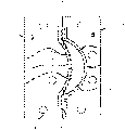
As shown in Figure 7, a kind of method that is used to increase the temperature of cavity surface in the moulded product process is to use induction heating method, even when moulded product had curved surface, described induction heating method also can provide even temperature to distribute on the whole surface of die cavity.
Carry out induction heating method in the following order: when mould is opened, load coil 23 is inserted in the mould, by eddy-current heating increase superficial layer temperature, load coil 23 is taken out and closing molding from mould.Because zone of heating is thin and heat-insulation layer is positioned on the back side of zone of heating, therefore, this method only make the temperature of cavity surface be increased to equably rapidly aspiration level aspect very effective.Also can use the method that directly electric current is connected in the zone of heating.Yet this method has some shortcomings, that is, electrode should be attached on the surface of die cavity tightly and be difficult to design makes constant current flow through the die cavity curved surface so that evenly increase the mould of temperature.On the contrary, induction heating method produces induced-current on the surface of the die cavity with any bending, and this method is evenly promptly to increase method of temperature.Usually, because the magnitude of current of being inducted and distance is square inversely proportional, so eddy-current heating causes increasing considerably of temperature being close on the surface of heater.Yet, if heat-insulation layer is not provided since heat towards the die matrix transmission, therefore above-mentioned temperature rise can not realize easily.On the contrary, the present invention includes the superficial layer 16 of low thermal mass, on superficial layer 16 back sides, have heat-insulation layer 17, therefore can increase the more temperature of certain layer.
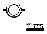
Employed induction heater is the heater coil type that is used for high-frequency heating among the present invention, so the shape of heater or size can change according to the type of die cavity.For example, in penetrating the situation of pressing method of molding, can use the induction coil that manufactures the die cavity form 23 as shown in Figure 7, and in the situation of blow moulding, can use the columniform a kind of induction coil that has as shown in Figure 15.
In the process of heating die cavity, the deficiency of thermal insulator will hinder temperature rise, and the control of temperature and heat energy also becomes difficult.If thermal insulator is provided during heating schedule, can store energy in the superficial layer so that be used for moulded product, yet too many thermal insulator also can hinder cooling program, therefore need suitably regulate the thickness of heat-insulation layer.
When as the method for carrying out cooling program energetically and by the microchannel circulating cooling fluid, as long as can not make casing deformation in molded program, the thickness of microchannel wall can be extremely thin.
Usually, between superficial layer and heat-insulation layer, there are differences aspect the thermal stress of heat consumption and savings.Described difference can cause layering or the separation between zone of heating and the heat-insulation layer.Therefore, expectation uses a kind of method to avoid described separation by the above-mentioned two-layer function of combination in inseparable homogenous material, and therefore as described below, the present inventor has described the preferred of this method
Embodiment.
Mould involved in the present invention is designed to be and comprises that thickness is about the shell 8 of 6mm, the surface that wherein constitutes die cavity has constituted superficial layer 16, and is the mechanical processing process of microchannel of 0.6-0.8mm or discharge mechanical processing process and heat-insulation layer 17 is formed on its back side by thickness.
Above-mentioned heat-insulation layer 17 is included as the space of the 20-90% of described heat-insulation layer cross-sectional area, preferably the space of 65-70%.The thickness of superficial layer is relevant with the amount of molded required heat energy.For example, level or process microchannel 15 vertically on the surface at shell 8 back sides so that in superficial layer, leave the thick edge of 1mm.Substitute microchannel 15 and can get out micropore 18.Can be on the back side on shell 8 surfaces level or form the said structure of microchannel 15 vertically in succession.Each microchannel 15 all is connected to each other or is connected to cooling pipeline 14 or 20 in the main body 4 of mould.So the shell 8 of processing is inserted in the shell receiver 10, and the boundary line 13 between the main body 4 of shell 8 and mould becomes on the parting surface 6 of the main body that is bonded on mould.Perhaps, if necessary, the surface at shell 8 back sides and the surface of shell receiver 10 can be engaged.
Examples of materials as shell comprises that described material can be carried out eddy-current heating such as iron, nickel, cobalt equimagnetic resonance material.The examples of materials that is used as the main body 4 of mould is that those have the material of high-termal conductivity and also can use above-mentioned material as shell.Although the material that is used for shell 8 is identical with material as the main body 4 of mould, the main body 4 of mould produces heat hardly.Because the magnitude of current of inducting when eddy-current heating and distance is square inversely proportional.
Here, the thickness of superficial layer and thermal energy are closely related.Therefore, the amount of the thermal mass of superficial layer is designed to be to have and is used for molded least energy,, improves the quality or the desired minimum thermal energy of function of moulded product that is.And the thickness of superficial layer is that material, predetermined temperature and the insulation degree according to shell designs.Therefore, when the needs more thermal energy, design superficial layer thicker.
In view of the foregoing, the preferred embodiments of the present invention provide the shell 8 that thickness is the low thermal mass of 1-25mm, and thickness is the superficial layer of 0.3-5.0mm, and the heat-insulation layer that is defined as accounting for the 20-90% space.
And, because superficial layer enough thick (for example 0.5mm or more than) and can not take place in the superficial layer separation case, also can prepare the superficial layer and the heat-insulation layer that are not with the integral form combination, but, the microchannel is machined on the main body 3 of mould and is inserted into so that engage for the purpose of simpler mold treatment and assembling.
Simultaneously, if any part that exists temperature can not increase on the surface of die cavity, the available nonmagnetic substance of the concrete part of this of shell is made so.So, will be not in this specific part can induced current, therefore will avoid temperature rise.
Employed cooling means is as described below among the present invention.After adding hot fluid, circulation makes that during moulding cyclc the time that required equipment is very complicated and moulding cyclc is required also becomes longer in the system of cooling fluid alternate cycles.Therefore, the present invention adopts a kind of method with the main body 4 of cooling die continuously in the moulding cyclc process.For this reason, thus the present inventor by in the main body 4 that will cool off pipeline 14 and be arranged at mould, by described cooling pipeline circulating cooling fluid or not only with the main body 4 of mould but also also have the microchannel 15 of heat-insulation layer 17 to be connected in the cooling pipeline 20 or 14 and make cooling fluid flow through microchannel 15 to carry out cooling program more energetically and carry out cooling program of the main body 4 of mould.
Perhaps, before heating, can remove the cooling fluid that cools off in pipeline 20 and the microchannel 15, so that strengthen the efficiency of heating surface by means of compressed air or vacuum.
By this program, the present invention can improve molded productivity by time that reduces moulding cyclc and quality and the function that improves moulded product.
In the present invention, on the surface of die cavity (promptly, on the superficial layer 16 of shell 8) carry out 0.5-20 50-400 ℃ the eddy-current heating in second, after taking out load coil 23, close described mould then, and moulding material is cast in mould, wherein when existing between the surface of mould and the moulding material when contacting, the heat energy of superficial layer 16 can improve the quality or the function of moulded product.Then, by cooling program temperature is cooled to preferred temperature within second at 0.1-20, so that cause the curing of quick cooling and moulded product, and after opening mould, moulded product is taken out from mould at last.In this cooling stage, can further reduce the required time of moulding cyclc by the cooling program of facilitating low thermal mass.
In a preferred embodiment of the invention, as shown in Figure 8, entire equipment comprise mould with cylindrical cavity, load coil 23, the cooling fluid pipeline 21 that is used to cool off in order to the heating cavity surface, during heating schedule in order to compressed-air line 22 of removing cooling fluid or the like.
Fig. 9 is the sketch of mould involved in the present invention.
Figure 10 shows the shell 8 of cavity surface, and wherein superficial layer 16 and heat-insulation layer 17 are combined as complete body.
Figure 11 a and Figure 11 b show respectively involved in the present invention during the heating and cooling according to time period reflection cavity surface on the chart of temperature change.Here, employed moulding material is a common straightcarbon steel.The power supply that is used for eddy-current heating is 18kw, and frequency is 15.3kHz, and the temperature of cooling fluid is 15 ℃.Made the temperature of cavity surface be increased to 245 ℃ in 1.4 seconds by heating from 95 ℃.Figure 11 a shows the situation of not using any special cooling fluid and cool off naturally in the microchannel 15 of heat-insulation layer 17, and spend 45 seconds it is cooled to 95 ℃, wherein to carry out after cooling off naturally for 0.6 second be the situation of using the pressure cooling of cooling fluid by the microchannel and Figure 11 b shows, its result shows, spends 0.5 second with it and be cooled to 95 ℃.
Figure 12 a and 12b are the enlarged drawings of Figure 11 b, so that better observation is provided.Figure 12 a reflected with Figure 11 b in identical situation, and Figure 12 b has reflected that wherein nature is the situation of forcing cooling after extending to for 2.8 seconds cool time.Naturally Leng Que duration or temperature are according to making the quality of moulded product and the amount that function maximizes desired heat energy determine.And operating condition changes according to the measured value of zone of heating and heat-insulation layer and the character of moulding material.When preheating, can will remove so that strengthen the efficiency of heating surface in order to cool off the cooling fluid that purpose flow in the heat-insulation layer in the cycle of front by means of compressed air or vacuum.
Method of moulding involved in the present invention and wherein employed mould also can be used in jet moulding, blow moulding, hot-forming method or the like.
It below is the example of blow moulding.
The present invention is applicable to the thermosetting process of PET bottle, and described technology can be designed to be and improve heat endurance, molded PET bottle with high thermal stability, and is lacking molded PET bottle in moulding cyclc.
USP 4476170 discloses, and the heat setting under 200-250 ℃ can form the product of the PET bottle with 100 ℃ or above high high-temp stability.Yet, in USP 4476170, carry out the heating and cooling program by the circulation that adds hot fluid and cooling fluid, this has caused the moulding cyclc of long period, has therefore reduced its industrial value.The present invention also has the invention of the PET bottle of outstanding heat endurance and outstanding productivity applicable to production.An example has been shown among Figure 13.
Use shell 8 of the present invention the main part of the superficial layer of mould promptly can be heated to 250 ℃ and cooling rapidly, divide 25 or can be it by the size that suitably Thickness Design of zone of heating and heat-insulation layer must be different from the main part of bottle and keep low temperature by form neck portion 24 and bottom with low magnetic resonance material simultaneously.
Load coil can be fabricated to columniform shown in Figure 14.The detailed composition and the cooling pipeline of shell 8 have been shown in Figure 15 and Figure 16 a-16c.The directionality of the microchannel of the shell among Figure 15 8 can be formulated for vertically or Figure 15 about the circumferencial direction of the bottle shown in the figure.
As mentioned above, the present invention uses a kind of like this shell, and wherein the lip-deep heat-insulation layer combination at the superficial layer of low thermal mass and its back side is called complete body, as the surface of die cavity; Use high-temp liquid round-robin method or high temp objects contact method promptly to increase the surface temperature of die cavity, or more particularly, use induction heating method, described method can obtain even temperature and distribute, irrelevant with the shape of product, therefore the temperature by heat-insulation layer and forced cooling method is controlled at increase promptly or chilling temperature and even temperature distribution in the short time; And provide a kind of method solving layering or separation problem, thus improved the quality and the function of moulded product, make minimize molded moulding cyclc simultaneously and improved the overall molded productivity relevant with moulded product.
And, the invention provides a kind of method, in order under restricted situation hardly, energetically temperature is increased to very high level so that improve the quality and the function of product, in order to by designing superficial layer and heat-insulation layer to such an extent that be suitable for being used for molded heat energy to control, in order to increase productivity by actual process for cooling, in order to improving durability by having the complete body that has superficial layer and heat-insulation layer, and by allowing machining or discharge process that outstanding applicability is provided.
Claims (16)
1. method that is used for moulded product said method comprising the steps of: heating die cavity superficial layer, is filled in the die cavity moulding material and cooling,
It is characterized in that described mould comprises:
A cavity,
A complete shell, it comprises:
A superficial layer, its as the surface of described cavity and
A heat-insulation layer, it comprise microchannel on the back side that is arranged in below the described superficial layer or micropore and
The main body of a described mould, described heat-insulation layer contacts with described main body;
The superficial layer of described die cavity is heated 0.5-20 by eddy-current heating and reaches 50-400 ℃ second; And
After moulding material is molded to described mould, make the superficial layer of described die cavity cool off in second at 0.1-20 by the microchannel circulating cooling fluid in the described heat-insulation layer on the circulating cooling fluid in the cooling pipeline in the main body of described mould and/or the back side below described superficial layer.
2. the method that is used for moulded product described in claim 1 is characterized in that, when needs were avoided temperature rise in the part of described cavity surface, the available low magnetic resonance material of the part of described shell replaced.
3. the method that is used for moulded product described in claim 1 is characterized in that, during described heating and described cooling step, makes cooling fluid circulate continuously by the cooling pipeline that is arranged in the described die main body.
4. the method that is used for moulded product described in claim 1 is characterized in that, during described cooling step, cooling fluid is by the circulation of described microchannel.
5. as any one described method that is used for moulded product in claim 1 and 4, it is characterized in that, during described heating steps, be stopped fully cooling fluid by the described microchannel in the heat-insulation layer circulation and from described microchannel, removed described cooling fluid by means of compressed air or vacuum after carry out described heating, and the circulation of cooling fluid be after cooling step during suitable in execution.
6. mould that is used for moulded product, described mould comprises
Cavity,
Complete shell, described shell comprises
Superficial layer with predetermined thickness, described superficial layer is as the surface of described cavity; And
Heat-insulation layer, described heat-insulation layer comprise microchannel or the micropore on the back side that is arranged in described superficial layer downside;
And the main body of described mould, described heat-insulation layer contacts with described main body.
7. the mould described in claim 6 is characterized in that, described shell is made of the material that can well heat by eddy-current heating.
8. the mould described in claim 6 is characterized in that, the described shell that is contacted with in the described main body only is engaged with in the left side and the boundary line on the parting surface between the right side of described mould.
9. as any one described mould in the claim 6 to 8, it is characterized in that the thickness of described shell is 1-25mm, and the thickness of described zone of heating is 0.3-10.0mm.
10. the mould described in claim 6 is characterized in that, described heat-insulation layer comprises microchannel or the micropore that its area portions is superficial layer 20-90%.
11. the mould described in claim 6 is characterized in that, described microchannel is that the shape with linear or waveform is formed in the described heat-insulation layer.
12., it is characterized in that described microchannel is that 0.3-10.0mm is wide as any described mould in the claim 6,7,8,10 and 11.
13. the mould described in claim 6 is characterized in that, the diameter of described micropore is 0.3-10.0mm.
14. the mould described in claim 6 is characterized in that, when needs were avoided temperature rise in the part of described cavity surface, the available low magnetic resonance material of the part that comprises zone of heating and heat-insulation layer of described shell replaced.
15. the mould described in claim 6 is characterized in that, for by cooling off pipeline circulating cooling fluid continuously, the cooling pipeline is arranged in the main body of described mould during heating and cooling.
16. the mould described in claim 6, it is characterized in that, except the described cooling pipeline of the main body that is used for described mould, cool off independently that pipeline directly is connected with the microchannel of described heat-insulation layer is similar to the cooling fluid of cold water so that during cooling circulate by described microchannel.
Applications Claiming Priority (2)
| Application Number | Priority Date | Filing Date | Title |
|---|---|---|---|
| KR2001/46364 | 2001-07-31 | ||
| KR20010046364 | 2001-07-31 |
Publications (2)
| Publication Number | Publication Date |
|---|---|
| CN1582222A CN1582222A (en) | 2005-02-16 |
| CN1274478C true CN1274478C (en) | 2006-09-13 |
Family
ID=19712760
Family Applications (1)
| Application Number | Title | Priority Date | Filing Date |
|---|---|---|---|
| CNB028150066A Expired - Fee Related CN1274478C (en) | 2001-07-31 | 2002-07-29 | Method for molding a product and a mold used therein |
Country Status (7)
| Country | Link |
|---|---|
| US (1) | US20040222566A1 (en) |
| EP (1) | EP1412152A2 (en) |
| JP (1) | JP2004536724A (en) |
| KR (1) | KR100542728B1 (en) |
| CN (1) | CN1274478C (en) |
| AU (1) | AU2002355701B2 (en) |
| WO (1) | WO2003011550A2 (en) |
Families Citing this family (40)
| Publication number | Priority date | Publication date | Assignee | Title |
|---|---|---|---|---|
| US10232530B2 (en) | 2005-06-22 | 2019-03-19 | Roctool | Induction heating device and method for making a workpiece using such a device |
| FR2887739B1 (en) * | 2005-06-22 | 2007-08-31 | Roctool Soc Par Actions Simpli | INDUCTION HEATING DEVICE AND METHOD FOR MANUFACTURING PARTS USING SUCH A DEVICE |
| CN100404226C (en) * | 2005-08-19 | 2008-07-23 | 重庆大学 | Inductive hot compacting dies for precision engineering plastic rubber products |
| DE102006023849B3 (en) * | 2006-05-19 | 2007-11-08 | Siegfried Hofmann Gmbh Werkzeugbau | Cooled insert, e.g. mold or core pin, for injection mold, is formed by melting solidified metal powder and has fine gas cooling channel(s) close to outer wall, ensuring effective heat abstraction |
| JP2008221514A (en) * | 2007-03-09 | 2008-09-25 | Konica Minolta Opto Inc | Injection molding method and optical element |
| US8021135B2 (en) | 2007-06-08 | 2011-09-20 | Sabic Innovative Plastics Ip B.V. | Mold apparatus for forming polymer and method |
| KR20100082842A (en) * | 2007-10-26 | 2010-07-20 | 사빅 이노베이티브 플라스틱스 아이피 비.브이. | System and method for forming polymer |
| US8657595B2 (en) | 2008-02-26 | 2014-02-25 | Roctool | Device for transforming materials by induction heating |
| US8360766B2 (en) * | 2008-10-28 | 2013-01-29 | Mitsubishi Heavy Industries Plastic Technology Co., Ltd. | Injection molding machine and injection molding method |
| AT507718B1 (en) | 2008-12-16 | 2010-11-15 | Engel Austria Gmbh | INJECTION MOLDING |
| CN201357532Y (en) * | 2009-03-13 | 2009-12-09 | 苏州红枫风电模具有限公司 | Electric heating and air cooling system for dies |
| WO2011035376A1 (en) * | 2009-09-24 | 2011-03-31 | Romar Engineering Pty Ltd | A mould or mould core and a method of manufacturing a mould or mould core |
| JP2011230445A (en) * | 2010-04-30 | 2011-11-17 | Neomax Material:Kk | Die and temperature-sensitive magnetic material for die |
| DE102011078167B4 (en) * | 2011-06-28 | 2014-03-13 | Joachim Hannebaum | Method for tempering an injection mold |
| FR2979047B1 (en) * | 2011-08-10 | 2014-09-19 | Roctool | PROVITF FOR ADJUSTING THE QUALITY FACTOR OF AN INDUCTION HEATING SYSTEM, IN PARTICULAR AN INDEPENDENT HEATING MOLD |
| FR2991902A1 (en) * | 2012-06-18 | 2013-12-20 | Roctool | METHOD AND DEVICE FOR PREHEATING A MOLD IN PARTICULAR INJECTION MOLDING |
| CN103085247B (en) * | 2013-02-28 | 2015-09-16 | 山东大学 | A kind of Steam Heating rapid thermal circulation injection mould |
| JP2016521215A (en) | 2013-03-15 | 2016-07-21 | ハーマン、ミラー、インコーポレイテッドHerman Miller Incorporated | Particulate foam parts having a textured surface |
| JP6504772B2 (en) * | 2013-09-19 | 2019-04-24 | キヤノン株式会社 | Injection molding apparatus, injection molding method and method of manufacturing molded article |
| EP2868455A1 (en) | 2013-11-04 | 2015-05-06 | Plastics Unbound Ltd | A method for injection molding plastic parts by means of an injection molding machine. |
| CA2929253C (en) | 2013-11-04 | 2023-01-24 | Plastic Unbound Ltd | An injection mold, injection molding tool comprising the injection mold, methods of theirs uses and objects obtained |
| EP3292970A1 (en) | 2014-03-28 | 2018-03-14 | Plastics Unbound Ltd | An injection mold, injection molding tool comprising the injection mold, methods of their uses |
| US10427329B2 (en) | 2014-06-27 | 2019-10-01 | Sabic Global Technologies B.V. | Induction heated mold apparatus with multimaterial core and method of using the same |
| GB201508655D0 (en) | 2015-05-20 | 2015-07-01 | Surface Generation Ltd | Method of moulding and mould tool |
| CN106079262A (en) * | 2016-06-25 | 2016-11-09 | 湖南惟晟信息科技有限公司 | The manufacture method of shaped article and mold for forming |
| GB201612294D0 (en) * | 2016-07-15 | 2016-08-31 | Rolls Royce Plc | Method and apparatus for particle injection moulding |
| FR3053906B1 (en) * | 2016-12-12 | 2018-08-17 | Sidel Participations | MOLDING DEVICE FOR IMPLEMENTING HOT MOLDING AND COLD MOLDING PROCESSES |
| US20190006154A1 (en) * | 2017-06-28 | 2019-01-03 | Chaolin Hu | Toroidal Plasma Chamber |
| DE102018127807A1 (en) * | 2018-04-26 | 2019-10-31 | Hanon Systems | Device and method for thermal joining, in particular a heat exchanger for a motor vehicle |
| US10953582B2 (en) | 2019-04-02 | 2021-03-23 | Acro Tool and Die Company | Mesh injection mold |
| US11148344B1 (en) | 2020-04-21 | 2021-10-19 | Elc Management Llc | Blow molding method and apparatus |
| CN111688086B (en) * | 2020-06-19 | 2022-03-11 | 江苏欣颍新材料科技有限公司 | Quick cooling device for casting billiards |
| DE102020118192A1 (en) * | 2020-07-09 | 2022-01-13 | Fox Velution Gmbh | Mold for producing a molded particle foam part |
| CN112223773A (en) * | 2020-09-27 | 2021-01-15 | 李建 | Novel ceramic forming resin rapid-pressing die |
| CN113134571B (en) * | 2021-04-15 | 2022-05-17 | 苏威新材料(徐州)有限公司 | Precoated sand forming die |
| KR102392611B1 (en) * | 2021-10-08 | 2022-04-29 | 서울과학기술대학교 산학협력단 | Cooling module with microporous cooling structure and local cooling method of mold using the same |
| DE102021132978A1 (en) * | 2021-12-14 | 2023-06-15 | Parat Beteiligungs Gmbh | Mold for producing a molded particle foam part |
| ES2957790A1 (en) * | 2022-06-20 | 2024-01-25 | Diseno E Modelado De Superficies S A | Injection mold and method for injection molding parts with said injection mold (Machine-translation by Google Translate, not legally binding) |
| FR3140009A1 (en) * | 2022-09-27 | 2024-03-29 | Knauf Industries Gestion | Chamber for steam molding of expanded or cellular materials or foams. |
| KR102583647B1 (en) * | 2022-11-29 | 2023-09-27 | 주식회사 나우산업 | Heterogeneous material insert mold unit with sealed air layer |
Family Cites Families (20)
| Publication number | Priority date | Publication date | Assignee | Title |
|---|---|---|---|---|
| US4340551A (en) * | 1980-08-11 | 1982-07-20 | Asahi-Dow Limited | Injection molded articles with improved surface characteristics, production of same and apparatus therefor |
| US4476170A (en) * | 1982-03-03 | 1984-10-09 | Owens-Illinois, Inc. | Poly(ethylene terephthalate) articles and method |
| EP0123707B1 (en) * | 1983-05-02 | 1987-10-21 | Ibm Deutschland Gmbh | Device consisting of a magnetic disc with a lubricant and a magnetic head, and process for manufacturing the device |
| NL8304399A (en) * | 1983-12-22 | 1985-07-16 | Philips Nv | ALTERNATING HEATABLE AND COOLABLE PRESS BLOCK. |
| JPS61290014A (en) * | 1985-06-18 | 1986-12-20 | Toyoda Gosei Co Ltd | Mold for slush molding |
| US4737096A (en) * | 1985-07-01 | 1988-04-12 | Kanaaldijk Z.W. | Injection mould with insert piece and injection moulding unit for same |
| JPS6378720A (en) * | 1986-09-24 | 1988-04-08 | Sekisui Chem Co Ltd | Molding die |
| JPH01159226A (en) * | 1987-12-17 | 1989-06-22 | Meiki Co Ltd | Molding tool for disc board |
| US5064597A (en) * | 1988-03-30 | 1991-11-12 | General Electric Company | Method of compression molding on hot surfaces |
| DE3832284A1 (en) * | 1988-09-22 | 1990-04-05 | Krupp Corpoplast Masch | Process and apparatus for thermally switching a body between a heating-up phase and a cooling-down phase for the treating of plastics |
| US5041247A (en) * | 1988-09-29 | 1991-08-20 | General Electric Company | Method and apparatus for blow molding parts with smooth surfaces |
| JP2826553B2 (en) * | 1989-06-09 | 1998-11-18 | 旭化成工業株式会社 | Decorative molding method and apparatus |
| US5084597A (en) * | 1990-11-02 | 1992-01-28 | Furnas Electric Co. | Drum switch construction |
| US6276656B1 (en) * | 1992-07-14 | 2001-08-21 | Thermal Wave Molding Corp. | Mold for optimizing cooling time to form molded article |
| JP4014232B2 (en) * | 1994-08-03 | 2007-11-28 | 旭化成ケミカルズ株式会社 | Electromagnetic induction heating mold for resin molding |
| DE4441815C2 (en) * | 1994-11-24 | 1997-09-18 | Tuhh Tech Gmbh | Method and device for producing plastic parts |
| JP2000127175A (en) * | 1998-10-28 | 2000-05-09 | Canon Inc | Molding machine |
| JP2000158505A (en) * | 1998-11-27 | 2000-06-13 | Asahi Chem Ind Co Ltd | Method for molding polyacetal resin |
| JP3977565B2 (en) * | 1999-05-06 | 2007-09-19 | 小野産業株式会社 | Mold for synthetic resin molding, mold temperature control device and mold temperature control method |
| JP2001113580A (en) * | 1999-10-21 | 2001-04-24 | Canon Inc | Injection molding machine |
-
2002
- 2002-07-29 JP JP2003516768A patent/JP2004536724A/en active Pending
- 2002-07-29 WO PCT/KR2002/001435 patent/WO2003011550A2/en active IP Right Grant
- 2002-07-29 AU AU2002355701A patent/AU2002355701B2/en not_active Ceased
- 2002-07-29 CN CNB028150066A patent/CN1274478C/en not_active Expired - Fee Related
- 2002-07-29 US US10/485,275 patent/US20040222566A1/en not_active Abandoned
- 2002-07-29 EP EP02751867A patent/EP1412152A2/en not_active Withdrawn
- 2002-07-29 KR KR1020020044697A patent/KR100542728B1/en active IP Right Grant
Also Published As
| Publication number | Publication date |
|---|---|
| KR20030011666A (en) | 2003-02-11 |
| WO2003011550A2 (en) | 2003-02-13 |
| AU2002355701B2 (en) | 2005-05-12 |
| WO2003011550A3 (en) | 2003-12-11 |
| EP1412152A2 (en) | 2004-04-28 |
| CN1582222A (en) | 2005-02-16 |
| JP2004536724A (en) | 2004-12-09 |
| US20040222566A1 (en) | 2004-11-11 |
| KR100542728B1 (en) | 2006-01-11 |
Similar Documents
| Publication | Publication Date | Title |
|---|---|---|
| CN1274478C (en) | Method for molding a product and a mold used therein | |
| CN101208993B (en) | Induction heating device and method for making parts using same | |
| AU2002355701A1 (en) | Method for molding a product and a mold used therein | |
| CN1270882C (en) | Injection forming method of preforming article | |
| JP4982519B2 (en) | Coaxial structure of cooling water channel and heat transfer coil, and mold having the coaxial structure of cooling water channel and heat transfer coil | |
| CN1234631C (en) | Molding shaper and method thereof | |
| JPWO2011104980A1 (en) | Preform and manufacturing method thereof | |
| TWI511858B (en) | Molding system and method for directly gas-cooling a molding object | |
| CN206536798U (en) | A kind of 3D metallic print die core inserts with the profile-followed heating function of conformal cooling | |
| CN1148359A (en) | Method for non-resin fluid-assisted injection molding of a resin | |
| CN1954986A (en) | Heater cartridge and molding apparatus having the same | |
| CN1148000A (en) | Process for injection molding preform of polyester resin injection screw and process for stretch blow molding the same | |
| CN101073909A (en) | Mould assembly | |
| CN2878025Y (en) | High cycle heating mould | |
| CN110271113A (en) | A kind of the consumptive material preparation method and device of continuous tow | |
| CN104551545B (en) | The strain-induced formula semisolid state forming device of a kind of fine grained texture bearing shell and technique | |
| CN105034266B (en) | The injection mold and its Shooting Technique of medical imaging X-ray thin-walled backlight box | |
| CN211194828U (en) | Injection molding machine capable of being cooled rapidly | |
| CN211467265U (en) | Automatic injection molding mold | |
| US6960746B2 (en) | Device for instantly pre-heating dies | |
| CN213887844U (en) | But rapid cooling's accurate mould | |
| CN209971280U (en) | Mould pressing equipment adopting mould central shaft for heating | |
| CN100404226C (en) | Inductive hot compacting dies for precision engineering plastic rubber products | |
| CN211683343U (en) | Waterway structure of centrifugal fan blade mold | |
| CN214188311U (en) | Quick cooling device of car injection molding |
Legal Events
| Date | Code | Title | Description |
|---|---|---|---|
| C06 | Publication | ||
| PB01 | Publication | ||
| C10 | Entry into substantive examination | ||
| SE01 | Entry into force of request for substantive examination | ||
| C14 | Grant of patent or utility model | ||
| GR01 | Patent grant | ||
| CF01 | Termination of patent right due to non-payment of annual fee |
Granted publication date: 20060913 Termination date: 20210729 |
|
| CF01 | Termination of patent right due to non-payment of annual fee |