CN1269265C - Connector with special arrangement signal contact and earthing contact - Google Patents
Connector with special arrangement signal contact and earthing contact Download PDFInfo
- Publication number
- CN1269265C CN1269265C CNB021067406A CN02106740A CN1269265C CN 1269265 C CN1269265 C CN 1269265C CN B021067406 A CNB021067406 A CN B021067406A CN 02106740 A CN02106740 A CN 02106740A CN 1269265 C CN1269265 C CN 1269265C
- Authority
- CN
- China
- Prior art keywords
- contact
- connector
- signal
- ground
- group
- Prior art date
- Legal status (The legal status is an assumption and is not a legal conclusion. Google has not performed a legal analysis and makes no representation as to the accuracy of the status listed.)
- Expired - Lifetime
Links
Images


Classifications
-
- H—ELECTRICITY
- H01—ELECTRIC ELEMENTS
- H01R—ELECTRICALLY-CONDUCTIVE CONNECTIONS; STRUCTURAL ASSOCIATIONS OF A PLURALITY OF MUTUALLY-INSULATED ELECTRICAL CONNECTING ELEMENTS; COUPLING DEVICES; CURRENT COLLECTORS
- H01R13/00—Details of coupling devices of the kinds covered by groups H01R12/70 or H01R24/00 - H01R33/00
- H01R13/648—Protective earth or shield arrangements on coupling devices, e.g. anti-static shielding
- H01R13/658—High frequency shielding arrangements, e.g. against EMI [Electro-Magnetic Interference] or EMP [Electro-Magnetic Pulse]
- H01R13/6581—Shield structure
- H01R13/6585—Shielding material individually surrounding or interposed between mutually spaced contacts
-
- H—ELECTRICITY
- H01—ELECTRIC ELEMENTS
- H01R—ELECTRICALLY-CONDUCTIVE CONNECTIONS; STRUCTURAL ASSOCIATIONS OF A PLURALITY OF MUTUALLY-INSULATED ELECTRICAL CONNECTING ELEMENTS; COUPLING DEVICES; CURRENT COLLECTORS
- H01R13/00—Details of coupling devices of the kinds covered by groups H01R12/70 or H01R24/00 - H01R33/00
- H01R13/646—Details of coupling devices of the kinds covered by groups H01R12/70 or H01R24/00 - H01R33/00 specially adapted for high-frequency, e.g. structures providing an impedance match or phase match
- H01R13/6461—Means for preventing cross-talk
- H01R13/6471—Means for preventing cross-talk by special arrangement of ground and signal conductors, e.g. GSGS [Ground-Signal-Ground-Signal]
-
- Y—GENERAL TAGGING OF NEW TECHNOLOGICAL DEVELOPMENTS; GENERAL TAGGING OF CROSS-SECTIONAL TECHNOLOGIES SPANNING OVER SEVERAL SECTIONS OF THE IPC; TECHNICAL SUBJECTS COVERED BY FORMER USPC CROSS-REFERENCE ART COLLECTIONS [XRACs] AND DIGESTS
- Y10—TECHNICAL SUBJECTS COVERED BY FORMER USPC
- Y10S—TECHNICAL SUBJECTS COVERED BY FORMER USPC CROSS-REFERENCE ART COLLECTIONS [XRACs] AND DIGESTS
- Y10S439/00—Electrical connectors
- Y10S439/941—Crosstalk suppression
Landscapes
- Details Of Connecting Devices For Male And Female Coupling (AREA)
- Coupling Device And Connection With Printed Circuit (AREA)
Abstract
A connector comprises a plurality of contact arrays parallel to one another. Each of the contact arrays includes two signal contacts (S) adjacent to each other and a ground contact (G) aligned with the signal contacts. In each contact array, the ground contact is located at a position corresponding to an intermediate position between two signal contacts in a next contact array.
Description
Technical field
The present invention relates to have the connector of many winding points, specifically, relate to a kind of connector that is suitable for the high-speed differential signal transmission.
Background technology
The high-speed differential signal transmission at first will be described.High-speed differential signal has two kinds of transmission meanss, promptly uneven (single-ended) type and balance (difference) type.Single-ended is a kind ofly to distinguish the pattern of high level and low level digital signal by the potential difference between earth connection and the holding wire, is the most general up to now.On the other hand, difference type is a kind of use two signal line (+,-), distinguishes high level and low level pattern by the potential difference between two signal line.In difference type, two voltage of signals level are equal to each other on two signal line, and mutual phase difference is 180 °.Compare with single-ended, owing to the noise that produces in two signal line is eliminated when receiver is imported, so difference type can guarantee reliable transmission.
In addition, according to TMDS (pass on minimum differential signal), also has another kind of transmission means.TMDS is the exchange standard of view data between PC main body and the monitor, is a kind of pattern of utilizing two signal line (+,-) and wall scroll earth connection to carry out transfer of data.
In a kind of existing connector that comprises a plurality of signal contacts and ground contact, utilize a kind of signal contact and ground contact made from the opposed facing structure of grid-like pattern, perhaps skip the structure of partial earthing contact.In preceding kind of structure, number of connections increases, so that is difficult to make connector to minimize.Plant in the structure in the back, the high frequency performance of connector is reduced greatly.
Current, in increasing software application, need the transmission of high-speed differential signal.In this case, require the connector construction compactness, price is low, high frequency performance is good.
Summary of the invention
Therefore, the purpose of this invention is to provide a kind of compact conformation, price is low, high frequency performance is good connector.
Along with proceeding to describe, will make other purpose of the present invention will become more clear.
According to one aspect of the present invention, a kind of connector with a plurality of contact groups that are parallel to each other is provided, each contact group comprises the ground contact of two signal contacts adjacent one another are and and described signal contact phase configuration, the ground contact in each contact group be arranged at next contact group in two adjacent signals contacts between corresponding position, centre position.
According to another aspect of the present invention, a kind of connector is provided, its first and second contacts group is parallel to each other, and the 3rd contact group is between the first and second contact groups; Comprise a plurality of signal contacts in each group in the described first and second contact groups, the 3rd contact group comprises a plurality of ground contacts; Each ground contact be arranged at each first and second contact group in corresponding position, centre position between the adjacent signals contact.
According to another aspect of the present invention, a kind of connector that is used for the high-speed differential signal transmission is provided, wherein, in the connector that constitutes by contact and insulator; Described contact has "+" signal contact and "-" signal contact and ground contact; The arrangement of described each connector, with described "+" signal contact and described "-" signal contact and described ground contact as one group, with respect to described ground contact, described "+" signal contact and described "-" signal contact constitute isosceles triangle, and the base of described isosceles triangle is configured to staggered alternately; End one side at described connector, configuration 2 row described "+" signal contact and described "-" signal contact and described ground contacts, in each row, after 2 described "+" signal contacts of configuration and described "-" signal contact, dispose 1 described ground contact; In the other end one side of described connector, configured in one piece 3 row described "+" signal contact and described "-" signal contact and described ground contacts in the row of centre, are arranged described ground contact.
Description of drawings
Figure 1A is the floor map according to the receptacle connector of first embodiment of the invention;
Figure 1B is the front view of Figure 1A receptacle connector;
Fig. 2 A is the plan view of receptacle connector shown in Figure 1A and the 1B;
Fig. 2 B is the partial cut away side views of Fig. 2 A receptacle connector;
Fig. 2 C is the front view of Fig. 2 A receptacle connector;
Fig. 2 D is the end view of Fig. 2 A receptacle connector;
Fig. 3 A is the plan view that is suitable for the plug-in connector that is connected with receptacle connector shown in Fig. 2 A-2D;
Fig. 3 B is the front view of Fig. 3 A plug-in connector;
Fig. 3 C is the end view of Fig. 3 A plug-in connector;
Fig. 4 is the plan view according to the receptacle connector of second embodiment of the invention;
Fig. 5 A is the plan view of receptacle connector shown in Figure 4;
Fig. 5 B is the partial cut away side views of receptacle connector shown in Fig. 5 A;
Fig. 5 C is the front view of Fig. 5 A receptacle connector;
Fig. 5 D is the end view of Fig. 5 A receptacle connector;
Fig. 6 A is the plan view that is suitable for the plug-in connector that is connected with receptacle connector shown in Fig. 5 A-5D;
Fig. 6 B is the front view of Fig. 6 A plug connector;
Fig. 6 C is the end view of Fig. 6 A plug connector;
Fig. 7 A is the plan view according to the receptacle connector of third embodiment of the invention;
Fig. 7 B is the front view of Fig. 7 A receptacle connector;
Fig. 8 A is the plan view of receptacle connector shown in Fig. 7 A and the 7B;
Fig. 8 B is the partial cut away side views of Fig. 8 A receptacle connector;
Fig. 8 C is the front view of Fig. 8 A receptacle connector;
Fig. 8 D is the end view of Fig. 8 A receptacle connector;
Fig. 9 is a plan view of describing the connection pattern of transmission cable;
Figure 10 A is the plan view of the syndeton between transmission cable and each receptacle connector;
Figure 10 B is the upward view of Figure 10 A syndeton;
Figure 10 C is the left view of Figure 10 A syndeton;
Figure 11 A is the plan view of a kind of remodeling of syndeton shown in Figure 10 A-10C;
Figure 11 B is the profile of being got along A-A line among Figure 11 A;
Figure 12 A-12J is the various views of used ground plate in each receptacle connector of expression;
Figure 13 A-13J is the various views of used barricade in each receptacle connector of expression;
Figure 14 A-14J is the ground plate that is coupled to each other of expression and the various views of barricade bonding state;
Figure 15 represent each joint and in circuit board, form in order to the spacing conversion figure between the through hole of admitting these joints.
Embodiment
The connector of first embodiment of the invention is at first described with reference to Figure 1A and 1B to Fig. 3 A-3C.
The connector of describing among these figure is a kind of receptacle connector 1.Shown in Figure 1B and 2A-2D, this receptacle connector 1 has a plurality of signal contact S, a plurality of ground contact G, a plurality of common (low speed) contact D, and the insulator 2 that these signal contacts S, ground contact G and assembling interconnecting D are installed, also have a jack housing 3 of surrounding all said elements.Adjacent one another are each comprises "+" signal contact and "-" signal contact to signal contact S.
Shown in Figure 1B, (S, G D) arrange by a kind of special arrangement with above-mentioned three kinds of contacts.In the superincumbent contact group, begin the contact arranged in sequence is become S S, G, S, S, G, D, D, D from the right side.In the contact group below, in order contact is arranged to G from the right side, S, S, G, S, S, D, D.Signal contact S adjacent one another are in the top contact group, the ground contact G in S and the following contact group is positioned on three summits of an isosceles triangle.Equally, above signal contact S adjacent one another are in ground contact G in the contact group and the following contact group, S is positioned on three summits of an isosceles triangle.
The upper surface of jack housing 3 is provided with a pair of spring 3A.This is suitable for cooperating with the plug-in connector 6 shown in Fig. 3 A-3C to spring 3A.
Referring to Fig. 3 A-3C, plug-in connector 6 comprises a plurality of signal contact S, a plurality of ground contact G, a plurality of assembling interconnecting D and the insulator 7 of these signal contacts S, ground contact G and assembling interconnecting D is installed, and a plug body 8 that surrounds above-mentioned all elements.
The upper surface of plug body 8 is provided with pair of holes 8A.This is suitable for cooperating with a pair of spring 3A of receptacle connector 1 respectively to hole 8A.
The connector of second embodiment of the invention is described to 6A-6C with reference to Fig. 4 below.
What describe among these figure is a kind of receptacle connector 11.Shown in Figure 4 and 5 A-5D, this receptacle connector 11 comprises a plurality of signal contact S, a plurality of ground contact G, a plurality of assembling interconnecting D, with the insulator 12 that these signal contacts S, ground contact G and assembling interconnecting D are installed, and a jack housing 13 of surrounding above-mentioned all elements.
With reference to Fig. 4, (S, G D) arrange by a kind of special arrangement with above-mentioned three kinds of contacts.In the contact group, begin the contact arranged in sequence is become S S, S, S, D, D from the right side in the above.In the intermediate contact group, begin the contact arranged in sequence is become G G, G, G, D, D from the right side.In the contact group, in order contact is arranged to S below, S, S, S, D from the right side.On three summits that signal contact S, S adjacent one another are and the ground contact G in the intermediate contact group are positioned at an isosceles triangle in the top contact group.Equally, signal contact S adjacent one another are in ground contact G in the intermediate contact group and the following contact group, S also are positioned on three summits of an isosceles triangle.
As Fig. 4, shown in 5A and the 5B, the upper surface of jack housing 13 is provided with pair of holes 13A.This is suitable for cooperating with the plug-in connector 16 shown in Fig. 6 A-6C to hole 13A.
Referring to Fig. 6 A-6C, plug-in connector 16 comprises a plurality of signal contact S, a plurality of ground contact G, a plurality of assembling interconnecting D, with the insulator 17 that these signal contacts S, ground contact G and assembling interconnecting D are installed, and a plug body 18 that surrounds above-mentioned all elements.
The upper surface of plug body 18 is provided with a pair of spring 18A.This is suitable for cooperating with the pair of holes 13A of receptacle connector 11 respectively to spring 18A.
With reference to Fig. 7 A, 7B and 8A-8D describe the connector of third embodiment of the invention below.
What describe among these figure is a kind of SMT (mounted on surface) type receptacle connector 21.Shown in Fig. 7 B and 8A-8D, receptacle connector 21 comprises a plurality of signal contact S, a plurality of ground contact G, a plurality of assembling interconnecting D, with the insulator 22 that these signal contacts S, ground contact G and assembling interconnecting D are installed, and the jack housing 23 of surrounding above-mentioned all elements.
Shown in Fig. 7 B, (S, G D) arrange by a kind of special arrangement with above-mentioned three kinds of contacts.In the contact group, begin the contact arranged in sequence is become S S, G, S, S, G, D, D, D from the right side in the above.In the contact group, begin the contact arranged in sequence is become G S, S, G, S, S, D, D from the right side below.Signal contact S adjacent one another are in the top contact group, the ground contact G in S and the following contact group is positioned on three summits of an isosceles triangle.Equally, above signal contact S adjacent one another are in ground contact G in the contact group and the following contact group, S also is positioned on three summits of an isosceles triangle.
Shown in Fig. 7 A, these contacts begin by S from the right side, G, and S, S, G, S, S, G, S, S, G, S, D, D, D, D, D is arranged sequentially in the line, and exposes from jack housing 23.
As Fig. 7 A, shown in 8A and the 8B, the upper surface of jack housing 23 is provided with a pair of spring 23A.This is suitable for cooperating with a plug-in connector (not shown) to spring 23A.
The syndeton and the transmission cable of each embodiment female connector are described to 11A and 11B now with reference to Fig. 9.
As shown in Figure 9, every transmission cable 31 has a central conductor 31A, is connected with each signal contact S.Each signal contact S has a terminal part that will be connected with printed circuit board (PCB) with ground contact G.These terminal parts are disposed in the line, make two signal contact S adjacent one another are, then arrange a ground contact G.Arrange these signal contacts S and ground contact G by predetermined spacing A.In this structure, leave the space in the face of in the zone of each ground contact G.Utilize this space that each transmission cable 31 can be set, the diameter of each bar transmission cable is greater than A, and less than 1.5A, the central conductor 31A of transmission cable 31 is connected with these signal contacts S.
In above-mentioned each connector, the plug-in connector that is connected with transmission cable on it is assemblied on the receptacle connector that is installed in printed circuit board (PCB).Each signal contact S, ground contact G and assembling interconnecting D can be surface installing type or the through hole type.
Referring to Figure 10 A-10D, these transmission cables 31 all have the masked segment 31B that is divided into group and organizes down.Last group and following winding floor 32 and 33 are overlapped, are inserted between group and the following set of shield part 31B.Last winding floor 32 has the coupling part 32A that links to each other with last set of shield part 31B.Following winding floor 33 has the coupling part 33A that links to each other with following set of shield part 31B.
Last group is provided with conductor part 32B and the 33B that will contact or weld with ground contact G with following winding floor 32 respectively with 33.Last group and following winding floor 32 and 33 face with each other conductor part 32B and 33B arranged alternate.In this manner, conductor part 32B and 33B are arranged with interlace mode and the ground contact G that is positioned on the described isosceles triangle summit is connected.
Shown in Figure 10 B, the conductor part 33B on following winding floor 33 is connected with the ground contact G of upper contact group, and the conductor part 32B that goes up winding floor 32 simultaneously is connected with the ground contact G of following contact group.In other words, shown in Figure 10 C, the conductor part 32B on last winding floor 32 is connected with upper contact winding ground contacts G, and the conductor part 33B on winding floor 33 is connected with the ground contact G of following contact group at present together.
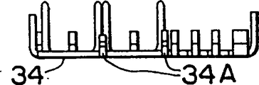
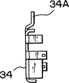
Shown in Figure 11 A and 11B, the masked segment 31B of each bar transmission cable 31 of both sides can be surrounded by the ground plate 34 of left and right and downside and by upside barricade 35 up and down.Like this, the masked segment 31B of transmission cable 31 is connected with described ground plate 34 and barricade 35.
With reference to Figure 12 A-12J, the ground plate 34 of the connector of seeing has from different directions been described wherein.One side of described ground plate 34 provides a pair of conductor part 34A that can be connected with the circuit that forms on the circuit board.
With reference to Figure 13 A-13J, wherein represented the barricade 35 of the connector seen from different directions.Described barricade 35 couples with ground plate 34, forms combining of described ground plate and barricade, shown in Figure 14 A-14J.
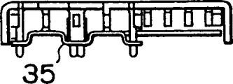
With reference to Figure 15, the spacing of the joint of establishing on the receptacle connector 1 36 will be described.
Claims (14)
1. a connector has the first and second contact groups that are parallel to each other, and the 3rd contact group between the described first and second contact groups; In the described first and second contact groups each comprises a plurality of signal contacts; Described the 3rd contact group comprises a plurality of ground contacts; Described each ground contact be set at described each first and second contact group in the adjacent signals contact between corresponding position, centre position.
2. connector as claimed in claim 1 wherein, is arranged signal contact described in described ground contact and described each first and second contact group by interlace mode.
3. connector as claimed in claim 1, wherein, described first, second, third contact group is disposed in the common plane.
4. connector as claimed in claim 1, wherein, described each signal contact has a Signal Terminal part, and described each ground contact has a grounding terminals part, and described Signal Terminal part and described grounding terminals partly are disposed in the same contact group.
5. connector as claimed in claim 4, wherein, described grounding terminals partly is disposed between the described adjacent Signal Terminal part.
6. one kind is used for the connector that high-speed differential signal transmits,
In the connector that constitutes by contact and insulator;
Described contact has "+" signal contact and "-" signal contact and ground contact;
The arrangement of described each connector, with described "+" signal contact and described "-" signal contact and described ground contact as one group, with respect to described ground contact, described "+" signal contact and described "-" signal contact constitute isosceles triangle, and the base of described isosceles triangle is configured to staggered alternately;
End one side at described connector, configuration amounts to 2 row described "+" signal contact and described "-" signal contact and described ground contacts, in each row, after configuration amounts to 2 described "+" signal contacts and described "-" signal contact in order, dispose 1 described ground contact;
In the other end one side of described connector, configured in one piece amounts to 3 row described "+" signal contact and described "-" signal contact and described ground contacts, in the row of centre, arranges described ground contact.
7. connector as claimed in claim 6, wherein, described connector is used for the high-speed differential signal transmission according to the TMDS standard.
8. connector as claimed in claim 6 wherein, is arranged described "+" signal contact, "-" signal contact and ground contact by predetermined spacing; Utilize the space in the face of described ground contact that many transmission cables are set, the described transmission cable of each bar links to each other with one of described "-" signal contact with described "+" signal contact.
9. connector as claimed in claim 8, wherein, described transmission cable is a kind of in the shielded type cable of twisting or the coaxial cable.
10. connector as claimed in claim 6, wherein, described connector is surface mounted on the printed circuit board (PCB), and described "+" signal contact, described "-" signal contact and described ground contact are disposed in the independent contact group on the described printed circuit board (PCB).
11. connector as claimed in claim 6 wherein, is arranged in described ground contact between described "+" signal contact and described "-" signal contact.
12. connector as claimed in claim 6, wherein, described connector is surface mounted on the printed circuit board (PCB), and described "+" signal contact, "-" signal contact and ground contact are arranged to three groups on described printed circuit board (PCB); The ground contact that is disposed in middle groups is in described three groups centre.
13. connector as claimed in claim 9, wherein, described transmission cable is described strand cable, described connector comprises winding floor and following winding floor, each group plate wherein all is connected with the masked segment of described twisting barricade, and described each that goes up in group and the following winding floor is organized all has the conductor part that contacts or weld with described ground contact; Described upward group and following winding floor are faced mutually; Described conductor part interlaced arrangement, and be connected with the ground contact that is positioned at described isosceles triangle summit.
14. connector as claimed in claim 7 wherein, is surrounded the masked segment of twisting shielded type cable by the barricade of left and right and downside ground plate and upside.
Applications Claiming Priority (4)
| Application Number | Priority Date | Filing Date | Title |
|---|---|---|---|
| JP60862/2001 | 2001-03-05 | ||
| JP2001060862 | 2001-03-05 | ||
| JP2001067706A JP3564555B2 (en) | 2001-03-05 | 2001-03-09 | High-speed differential signal transmission connector |
| JP67706/2001 | 2001-03-09 |
Publications (2)
| Publication Number | Publication Date |
|---|---|
| CN1374719A CN1374719A (en) | 2002-10-16 |
| CN1269265C true CN1269265C (en) | 2006-08-09 |
Family
ID=26610657
Family Applications (1)
| Application Number | Title | Priority Date | Filing Date |
|---|---|---|---|
| CNB021067406A Expired - Lifetime CN1269265C (en) | 2001-03-05 | 2002-03-05 | Connector with special arrangement signal contact and earthing contact |
Country Status (8)
| Country | Link |
|---|---|
| US (1) | US6935870B2 (en) |
| EP (1) | EP1239552B1 (en) |
| JP (1) | JP3564555B2 (en) |
| KR (1) | KR100461260B1 (en) |
| CN (1) | CN1269265C (en) |
| DE (1) | DE60200559T2 (en) |
| DK (1) | DK1239552T3 (en) |
| TW (1) | TW580783B (en) |
Families Citing this family (71)
| Publication number | Priority date | Publication date | Assignee | Title |
|---|---|---|---|---|
| CN1870853B (en) * | 2001-10-10 | 2012-01-18 | 莫莱克斯公司 | Circuit board layouts of high speed differential signal edge card connector |
| US7039417B2 (en) | 2003-09-25 | 2006-05-02 | Lenovo Pte Ltd | Apparatus, system, and method for mitigating access point data rate degradation |
| AU2003245636A1 (en) | 2002-06-21 | 2004-01-06 | Molex Incorporated | High-density, impedance-tuned connector having modular construction |
| US6863549B2 (en) | 2002-09-25 | 2005-03-08 | Molex Incorporated | Impedance-tuned terminal contact arrangement and connectors incorporating same |
| WO2004030158A2 (en) * | 2002-09-25 | 2004-04-08 | Molex Incorporated | Impedance-tuned terminal contact arrangement and connectors incorporating same |
| JP4082604B2 (en) | 2003-04-09 | 2008-04-30 | 矢崎総業株式会社 | connector |
| CN100561608C (en) * | 2003-11-22 | 2009-11-18 | 鸿富锦精密工业(深圳)有限公司 | Eliminate the differential pair spread pattern that high-speed digital circuit is crosstalked |
| EP1841298A3 (en) * | 2004-02-13 | 2008-05-07 | Molex Incorporated | Plated vias exit structure for printed circuit board |
| US20050201065A1 (en) * | 2004-02-13 | 2005-09-15 | Regnier Kent E. | Preferential ground and via exit structures for printed circuit boards |
| US7448909B2 (en) | 2004-02-13 | 2008-11-11 | Molex Incorporated | Preferential via exit structures with triad configuration for printed circuit boards |
| JP4036376B2 (en) | 2004-04-09 | 2008-01-23 | 日本航空電子工業株式会社 | connector |
| SG117589A1 (en) * | 2004-06-03 | 2005-12-29 | Tyco Electronics Amp Kk | Board mounting electrical connector |
| JP4613043B2 (en) * | 2004-10-19 | 2011-01-12 | 日本航空電子工業株式会社 | connector |
| EP1810552A1 (en) | 2004-10-29 | 2007-07-25 | Molex Incorporated | Printed circuit board for high-speed electrical connectors |
| JP4324566B2 (en) * | 2005-01-21 | 2009-09-02 | ホシデン株式会社 | Memory card adapter |
| TWI284950B (en) * | 2005-05-19 | 2007-08-01 | Via Tech Inc | Chip structure with arrangement of side pads |
| CN1905283B (en) * | 2005-07-29 | 2010-05-26 | 东莞市夏亿电子科技有限公司 | Electric connector |
| KR100827267B1 (en) | 2005-09-16 | 2008-05-07 | 니혼 고꾸 덴시 고교 가부시끼가이샤 | Electrical connector capable of suppressing crosstalk |
| JP2007080782A (en) | 2005-09-16 | 2007-03-29 | Japan Aviation Electronics Industry Ltd | Electric connector |
| JP4190015B2 (en) * | 2005-11-02 | 2008-12-03 | 日本航空電子工業株式会社 | connector |
| JP4623584B2 (en) * | 2005-12-28 | 2011-02-02 | 日本航空電子工業株式会社 | connector |
| JP4551868B2 (en) | 2005-12-28 | 2010-09-29 | 日本航空電子工業株式会社 | connector |
| JP4216287B2 (en) | 2006-02-20 | 2009-01-28 | 日本航空電子工業株式会社 | connector |
| CN2932689Y (en) * | 2006-04-10 | 2007-08-08 | 富士康(昆山)电脑接插件有限公司 | Electric connector |
| DE102007032787B8 (en) * | 2006-07-14 | 2010-11-25 | Japan Aviation Electronics Industry, Ltd. | An electrical connector and electrical component having contact terminal portions arranged in a generally trapezoidal shape |
| US7549897B2 (en) | 2006-08-02 | 2009-06-23 | Tyco Electronics Corporation | Electrical connector having improved terminal configuration |
| US8142236B2 (en) | 2006-08-02 | 2012-03-27 | Tyco Electronics Corporation | Electrical connector having improved density and routing characteristics and related methods |
| US7753742B2 (en) | 2006-08-02 | 2010-07-13 | Tyco Electronics Corporation | Electrical terminal having improved insertion characteristics and electrical connector for use therewith |
| US7670196B2 (en) | 2006-08-02 | 2010-03-02 | Tyco Electronics Corporation | Electrical terminal having tactile feedback tip and electrical connector for use therewith |
| JP2009037971A (en) * | 2007-08-03 | 2009-02-19 | Tyco Electronics Amp Kk | Board-mounting connector |
| JP5019174B2 (en) * | 2007-08-03 | 2012-09-05 | 山一電機株式会社 | High-speed transmission connector |
| TWI446630B (en) * | 2007-08-23 | 2014-07-21 | Molex Inc | Board mounted electrical connector |
| JP4862796B2 (en) * | 2007-09-28 | 2012-01-25 | 山一電機株式会社 | High-density connector for high-speed transmission |
| US7727025B2 (en) * | 2007-10-09 | 2010-06-01 | Tyco Electronics Corporation | Modular electrical connector with enhanced plug interface |
| CN201122731Y (en) * | 2007-10-25 | 2008-09-24 | 上海莫仕连接器有限公司 | Electrical connector |
| JP4548802B2 (en) * | 2008-01-29 | 2010-09-22 | 日本航空電子工業株式会社 | connector |
| JP4522454B2 (en) * | 2008-02-04 | 2010-08-11 | 日本航空電子工業株式会社 | connector |
| JP2009193786A (en) * | 2008-02-13 | 2009-08-27 | Yamaichi Electronics Co Ltd | Connector for standard hdmi cable |
| JP4671444B2 (en) | 2008-02-20 | 2011-04-20 | 日本航空電子工業株式会社 | connector |
| JP4459273B2 (en) | 2008-02-20 | 2010-04-28 | 日本航空電子工業株式会社 | connector |
| WO2009115922A2 (en) | 2008-02-26 | 2009-09-24 | Molex Incorporated | Impedance controlled electrical connector |
| JP5100449B2 (en) * | 2008-03-05 | 2012-12-19 | キヤノン株式会社 | Composite connector and electronic device including the same |
| US7748997B2 (en) * | 2008-07-22 | 2010-07-06 | Tyco Electronics Corporation | Receptacle for electrical connectors |
| JP4567079B2 (en) | 2008-08-22 | 2010-10-20 | 日本航空電子工業株式会社 | connector |
| JP4565031B2 (en) * | 2008-09-17 | 2010-10-20 | 山一電機株式会社 | High-speed transmission connector, high-speed transmission connector plug, and high-speed transmission connector socket |
| US7972151B2 (en) * | 2009-01-05 | 2011-07-05 | Hon Hai Precision Ind. Co., Ltd. | Electrical connector with improved arrangement of ground and signal contacts |
| US8066532B2 (en) * | 2009-01-18 | 2011-11-29 | Hon Hai Precision Ind. Co., Ltd. | Electrical connector assembly with improved contact arrangement and metallic shell |
| JP2010244901A (en) | 2009-04-07 | 2010-10-28 | Japan Aviation Electronics Industry Ltd | Connector |
| US8932081B2 (en) | 2009-07-01 | 2015-01-13 | Molex Incorporated | Connector with terminal retention |
| TWI376842B (en) * | 2009-09-18 | 2012-11-11 | Via Tech Inc | Lead arrangement, electric connector and electric assembly |
| US8740651B2 (en) | 2009-09-18 | 2014-06-03 | Via Technologies, Inc. | Lead arrangement, electric connector and electric assembly |
| JP4828626B2 (en) * | 2009-10-20 | 2011-11-30 | 日本航空電子工業株式会社 | connector |
| DE102009057260A1 (en) * | 2009-12-08 | 2011-08-04 | ERNI Electronics GmbH, 73099 | Relief connector and multilayer board |
| CN102117978B (en) * | 2009-12-30 | 2014-07-30 | 富士康(昆山)电脑接插件有限公司 | Electric connector |
| CN102315534B (en) * | 2010-07-08 | 2014-08-20 | 泰科电子(上海)有限公司 | Electric connector |
| JP4976568B1 (en) * | 2011-04-18 | 2012-07-18 | 日本航空電子工業株式会社 | connector |
| CN102916281B (en) * | 2011-08-05 | 2015-04-01 | 上海莫仕连接器有限公司 | Plug electric connector, socket electric connector and electric connector combination |
| MY167297A (en) | 2011-08-05 | 2018-08-16 | Molex Interconnect Shanghai Co | Electrical connector with power terminals |
| JP5727902B2 (en) * | 2011-09-13 | 2015-06-03 | ホシデン株式会社 | connector |
| CN103094736B (en) * | 2011-11-07 | 2015-07-08 | 富士康(昆山)电脑接插件有限公司 | Cable connecting device assembly |
| CN202772376U (en) * | 2012-08-29 | 2013-03-06 | 泰科电子(上海)有限公司 | Connector |
| US9853388B2 (en) * | 2013-11-27 | 2017-12-26 | Fci Americas Technology Llc | Electrical power connector |
| TWI581517B (en) * | 2014-07-14 | 2017-05-01 | 連展科技股份有限公司 | Socket electrical connector |
| US9338879B2 (en) * | 2014-07-17 | 2016-05-10 | Via Technologies, Inc. | Through-hole layout structure including first and second pairs of differential signal through-holes disposed between three ground through-holes |
| JP6330587B2 (en) * | 2014-09-04 | 2018-05-30 | 株式会社オートネットワーク技術研究所 | Communication connector |
| US9496651B2 (en) * | 2015-03-03 | 2016-11-15 | Lattice Semiconductor Corporation | HDMI connector |
| CN204966770U (en) * | 2015-07-25 | 2016-01-13 | 富士康(昆山)电脑接插件有限公司 | Electric connector |
| CN108141677B (en) | 2015-10-26 | 2020-02-14 | 华为技术有限公司 | Loudspeaker module, audio compensation method and device |
| CN107978926B (en) * | 2016-10-21 | 2020-06-30 | 泰科电子(上海)有限公司 | Connector with a locking member |
| CN107221820B (en) * | 2017-06-29 | 2024-02-27 | 深圳市深台帏翔电子有限公司 | Terminal equipment and integrated connector thereof |
| CN109586067B (en) * | 2018-10-23 | 2020-06-09 | 番禺得意精密电子工业有限公司 | Electrical connector |
Family Cites Families (19)
| Publication number | Priority date | Publication date | Assignee | Title |
|---|---|---|---|---|
| JPH03110772A (en) | 1989-09-22 | 1991-05-10 | Tanaka Kikinzoku Kogyo Kk | Manufacture of multiwire bundle sliding brush element |
| JP2587316B2 (en) * | 1990-10-08 | 1997-03-05 | 第一電子工業株式会社 | Multi-pole electrical connector for coaxial flat cable |
| JP2739608B2 (en) * | 1990-11-15 | 1998-04-15 | 日本エー・エム・ピー株式会社 | Multi-contact type connector for signal transmission |
| JPH04269479A (en) | 1991-02-25 | 1992-09-25 | Fujitsu Ltd | High density connector |
| JP3415889B2 (en) | 1992-08-18 | 2003-06-09 | ザ ウィタカー コーポレーション | Shield connector |
| JPH06104030A (en) * | 1992-09-18 | 1994-04-15 | Mitsubishi Electric Corp | Connector |
| US5525067A (en) * | 1994-02-03 | 1996-06-11 | Motorola, Inc | Ground plane interconnection system using multiple connector contacts |
| US5716236A (en) * | 1996-03-01 | 1998-02-10 | Molex Incorporated | System for terminating the shield of a high speed cable |
| US5711686A (en) | 1996-03-01 | 1998-01-27 | Molex Incorporated | System for terminating the shield of a high speed cable |
| US5895276A (en) * | 1996-11-22 | 1999-04-20 | The Whitaker Corporation | High speed and high density backplane connector |
| US5876248A (en) * | 1997-01-14 | 1999-03-02 | Molex Incorporated | Matable electrical connectors having signal and power terminals |
| JPH1167369A (en) * | 1997-08-18 | 1999-03-09 | Japan Aviation Electron Ind Ltd | Connector suitable for fast transmission |
| US5961355A (en) | 1997-12-17 | 1999-10-05 | Berg Technology, Inc. | High density interstitial connector system |
| JP3236994B2 (en) | 1998-02-27 | 2001-12-10 | 日本航空電子工業株式会社 | connector |
| JPH11251003A (en) * | 1998-02-27 | 1999-09-17 | Yokowo Co Ltd | Zif connector |
| CN100409503C (en) * | 1999-07-16 | 2008-08-06 | 莫列斯公司 | Impedance-tumed connector |
| US6280209B1 (en) * | 1999-07-16 | 2001-08-28 | Molex Incorporated | Connector with improved performance characteristics |
| JP3678990B2 (en) | 2000-03-31 | 2005-08-03 | タイコエレクトロニクスアンプ株式会社 | Electrical connector assembly and female connector |
| US6350134B1 (en) * | 2000-07-25 | 2002-02-26 | Tyco Electronics Corporation | Electrical connector having triad contact groups arranged in an alternating inverted sequence |
-
2001
- 2001-03-09 JP JP2001067706A patent/JP3564555B2/en not_active Expired - Lifetime
-
2002
- 2002-02-27 DE DE60200559T patent/DE60200559T2/en not_active Expired - Fee Related
- 2002-02-27 EP EP02004531A patent/EP1239552B1/en not_active Expired - Lifetime
- 2002-02-27 DK DK02004531T patent/DK1239552T3/en active
- 2002-03-01 TW TW091103808A patent/TW580783B/en not_active IP Right Cessation
- 2002-03-05 CN CNB021067406A patent/CN1269265C/en not_active Expired - Lifetime
- 2002-03-05 US US10/090,956 patent/US6935870B2/en not_active Expired - Lifetime
- 2002-03-05 KR KR10-2002-0011613A patent/KR100461260B1/en active IP Right Grant
Also Published As
| Publication number | Publication date |
|---|---|
| TW580783B (en) | 2004-03-21 |
| JP3564555B2 (en) | 2004-09-15 |
| DK1239552T3 (en) | 2004-10-04 |
| US6935870B2 (en) | 2005-08-30 |
| KR20020071477A (en) | 2002-09-12 |
| JP2002334748A (en) | 2002-11-22 |
| EP1239552A1 (en) | 2002-09-11 |
| DE60200559T2 (en) | 2005-06-30 |
| DE60200559D1 (en) | 2004-07-08 |
| EP1239552B1 (en) | 2004-06-02 |
| KR100461260B1 (en) | 2004-12-10 |
| CN1374719A (en) | 2002-10-16 |
| US20020123254A1 (en) | 2002-09-05 |
Similar Documents
| Publication | Publication Date | Title |
|---|---|---|
| CN1269265C (en) | Connector with special arrangement signal contact and earthing contact | |
| CN1169265C (en) | Connector for processing different kinds of signals including high-speed signals | |
| CN100459312C (en) | Electric connector for connecting connection objects | |
| CN102394398B (en) | Connector assembly having a mating adapter | |
| CN1139151C (en) | Electrical connector | |
| CN2821900Y (en) | Module connector | |
| CN1127780C (en) | High density electrical connector | |
| CN1278455C (en) | Differential signal electric connector | |
| CN1728473A (en) | Coaxial connector for board-to-board connection | |
| CN1992441A (en) | Connector | |
| KR101478938B1 (en) | Connector | |
| CN1960067A (en) | Connector in which a mutual distance between contacts is adjusted at terminal portions thereof | |
| CN102176561A (en) | Modular connector system | |
| CN1653654A (en) | Card-insertion terminal for shielded cable | |
| CN1992448A (en) | Connector in which a balance in physical distance between a ground contact and a pair of signal contacts can be maintained | |
| CN1397101A (en) | Electrical cornector having customizable circuit board wafers | |
| CN1790814A (en) | Shielded high-density edge connector | |
| CN1998113A (en) | Electric connector | |
| CN101036270A (en) | Connector | |
| CN1215614C (en) | Electric connector and transmission line | |
| CN2831476Y (en) | Modular connector | |
| CN1247396A (en) | Adaptable terminal plug device | |
| CN1204655C (en) | Shielded backplane connector | |
| US6783400B2 (en) | Electrical connector assembly having contacts configured for high-speed signal transmission | |
| CN2563785Y (en) | Rectangular filter electric connector |
Legal Events
| Date | Code | Title | Description |
|---|---|---|---|
| C10 | Entry into substantive examination | ||
| SE01 | Entry into force of request for substantive examination | ||
| C06 | Publication | ||
| PB01 | Publication | ||
| C10 | Entry into substantive examination | ||
| SE01 | Entry into force of request for substantive examination | ||
| C14 | Grant of patent or utility model | ||
| GR01 | Patent grant | ||
| CX01 | Expiry of patent term | ||
| CX01 | Expiry of patent term |
Granted publication date: 20060809 |