CN1267960C - Colour picture tube device - Google Patents
Colour picture tube device Download PDFInfo
- Publication number
- CN1267960C CN1267960C CNB001202286A CN00120228A CN1267960C CN 1267960 C CN1267960 C CN 1267960C CN B001202286 A CNB001202286 A CN B001202286A CN 00120228 A CN00120228 A CN 00120228A CN 1267960 C CN1267960 C CN 1267960C
- Authority
- CN
- China
- Prior art keywords
- coil
- choke
- magnetic field
- yoke current
- quadrupole
- Prior art date
- Legal status (The legal status is an assumption and is not a legal conclusion. Google has not performed a legal analysis and makes no representation as to the accuracy of the status listed.)
- Expired - Fee Related
Links
Images


Classifications
-
- H—ELECTRICITY
- H04—ELECTRIC COMMUNICATION TECHNIQUE
- H04N—PICTORIAL COMMUNICATION, e.g. TELEVISION
- H04N9/00—Details of colour television systems
- H04N9/12—Picture reproducers
- H04N9/16—Picture reproducers using cathode ray tubes
- H04N9/28—Arrangements for convergence or focusing
-
- H—ELECTRICITY
- H01—ELECTRIC ELEMENTS
- H01J—ELECTRIC DISCHARGE TUBES OR DISCHARGE LAMPS
- H01J29/00—Details of cathode-ray tubes or of electron-beam tubes of the types covered by group H01J31/00
- H01J29/46—Arrangements of electrodes and associated parts for generating or controlling the ray or beam, e.g. electron-optical arrangement
- H01J29/70—Arrangements for deflecting ray or beam
- H01J29/701—Systems for correcting deviation or convergence of a plurality of beams by means of magnetic fields at least
- H01J29/702—Convergence correction arrangements therefor
- H01J29/705—Dynamic convergence systems
Abstract
A color display tube device includes a composite correction circuit having a series circuit of a first reactor coil and a first four-pole coil and a series circuit of a second reactor coil with a polarity opposite to that of the first reactor coil and a second four-pole coil, the two series circuits being connected in parallel, and a vertical control coil for applying a magnetic bias that changes in synchronization with a vertical deflection current to the first and second reactor coils. The composite correction circuit is connected in series to horizontal deflection coils. In the color display tube device using an in-line self-convergence system, it is made possible to correct a PQH mis-convergence and reduce pincushion distortion at the left and right occurring before correction by a monitor set while preventing deterioration of the focus performance.
Description
Technical field
The present invention relates to the colour display tube electronic gun device that uses in television set or the computer display etc., be specifically related to be used to improve the structure of the deflection circuit of convergence.
Background technology
In recent years, the complanation of chromoscope panel is in continuous propelling.If the deflection system that the chromoscope of previous surface panel is used intactly is used for the chromoscope of plane panel, exist so up and down and about the problem that increases easily of pincushion distortion.Therefore, constantly be devoted to improve these distortions.
In the problems referred to above, as the device of proofreading and correct top bottoms pincushion, generally in the additional magnet up and down of the fluorescence screen side of deflection system.This is under the strong pincushion field that magnet produces, and utilizes the effect that electron beam is pulled to vertical direction.Its result with regard to the misconvergence on the vertical axis (YH), under the automatic converging system situation, as shown in figure 10, is easy to generate the residual misconvergence of pincushion.Along with the complanation of screen panel surface, because the tendency that top bottoms pincushion increases, so further improve the intensity of the magnetic field of magnets of proofreading and correct this distortion, the residual misconvergence of YH pincushion increases all the more.
In order to address this problem, at additional quadrupole coil and the YH correcting circuit that produces quadripolar magnetic field of the electron gun side of deflection system, in these circuit, flow through vertical yoke current, carry out YH and proofread and correct.The principle that this YH proofreaies and correct is, enter at electron beam before the main field of deflection system generation, the quadripolar magnetic field that utilizes quadrupole coil to produce produces and the power of side electron beam mutual spacing from increasing, thus, make and the action effect of side electron beam mutual spacing after counteracting enters main field from close power.Make this quadripolar magnetic field synchronous in vertical direction, produce intensity and the proportional quadripolar magnetic field of vertical yoke current.In order to produce the quadripolar magnetic field of the same polarity that has nothing to do with deflection polarity, the rectification circuit that additional diode forms.
On the other hand,, utilize monitor to set the pincushion correction circuit of side, can proofread and correct for side pinuchsion.
Secondly,, can consider, the distortion of electron-beam point shape is reduced, reduce the some shape difference between three-beam electron-beam by weakening the pincushion field of horizontal deflection magnetic field in order to improve focusing performance.But, in the method, under the situation of the automatic converging system of in-line chromoscope, as shown in figure 11, have the problem that produces the barrel-shaped residual misconvergence of ordinate misconvergence (XH) on the trunnion axis.
In order to address this problem, as shown in figure 12, open the circuit that adopts the quadrupole coil 51 that the deflection system electron gun side is provided with to form the such distribution of bridge by four coils 52,53,54,55 of saturable choke in the invention that discloses in the clear 63-94542 communique the spy.In this circuit by horizontal yoke current, by producing quadripolar magnetic field with the irrelevant same polarity of the polarity of deflection current, correcting electronic bundle point with the proportional quadripolar magnetic field of horizontal yoke current.In this mode,, proofread and correct so can also realize XH because XH is also changing simultaneously.In this circuit, utilize the work of saturable choke, when the positive direction half period (left avertence commentaries on classics), the inductance of coil 52,55 shown in Figure 12 reduces, and when the negative direction half period (right avertence commentaries on classics), the inductance of coil 53,54 reduces.Therefore, no matter under which kind of situation, the illustrated horizontal yoke current from the top down that in quadrupole coil 51, flows, the magnetic field that produces same polarity.Use such simpler structure, can carry out XH and proofread and correct.
But as mentioned above, owing to strengthen the magnetic field of magnets that top bottoms pincushion is proofreaied and correct, so utilizing in the past YH to proofread and correct under the situation of YH correcting value of increase, the YH correcting value is compared in the bight extended with the correcting value on the vertical axis.Therefore, as shown in figure 13,, on the bight, the problem of red beam the right figure generation of misconvergence (PQH) between ordinate side electron beam is arranged also even the YH on the vertical axis is proofreaied and correct by the best.
Therefore, in order not enlarge the YH correcting value, can consider reduce the residual misconvergence of pincushion, the method of the barrel-shaped distortion of the vertical magnetic field of reinforcement deflection system, but in the method, owing to cause the increase of top bottoms pincushion once more, do not set so obtain to realize compromise with PQH red beam the right figure.
On the other hand, just be accompanied by that screen panel surface complanation causes, the increase of side pinuchsion does not only enlarge the device of the pillow distortion equalizing amount of monitoring arrangement, has along with correcting value enlarges the problem that consumed power increases.
Summary of the invention
The present invention in the in-line automatic converging system, provides the deterioration that can prevent focusing performance for solving above-mentioned problem, proofreaies and correct the PQH misconvergence simultaneously, and, reduce the colour display tube electronic gun device that monitoring arrangement is proofreaied and correct preceding side pinuchsion.
Colour display tube electronic gun device complex correction circuit of the present invention, this circuit is the body and be connected in parallel with the second choke coil of the described first choke coil opposite polarity and the body that is connected in series of second quadrupole coil of being connected in series of the first choke coil and first quadrupole coil, with vertical control coil, in the described first and second choke coils, apply the magnetic bias that changes synchronously with vertical yoke current, it is characterized in that described complex correction circuit and horizontal deflection coil are connected in series; The intensity of the quadripolar magnetic field that described quadrupole coil produces is followed the increase of horizontal yoke current and is increased, and when vertical yoke current is maximum, compare with the magnetic field on the trunnion axis and to weaken, the total inductance of horizontal deflection system, with on the trunnion axis about hold and compare, when the deflection of bight, increase.
According to this structure, magnetic bias and vertical yoke current in the choke coil are changed synchronously, make the first and second choke coils alternately saturated, quadrupole coil that can switch operating according to the degree of deflection.Thus, top bottoms pincushion is increased, corrected X H misconvergence is proofreaied and correct the PQH misconvergence, and can reduce the side pinuchsion before monitoring arrangement is proofreaied and correct.
Preferably also in the first and second choke coils, be furnished with the magnet that forms certain magnetic bias in the said structure, constitute the saturable choke by the first and second choke coils, vertical control coil and magnet.And, it is saturated structurally to have during the half period of horizontal yoke current positive direction the first choke coil, the quadripolar magnetic field that first quadrupole coil produces plays dominating role, the second choke coil is saturated during the half period of horizontal yoke current negative direction, and the quadripolar magnetic field that second quadrupole coil produces plays dominating role.
According to the present invention, can make misconvergence amount change between the ordinate side electron beam on the phosphor screen trunnion axis, obtain the convergence of expectation.Meanwhile, by in vertical control coil, being flowing in the vertical yoke current of rectification on the positive direction electric current, the intensity and the vertical yoke current of the quadripolar magnetic field of first and second quadrupole coils generation are changed synchronously, make that the misconvergence amount changes between the side electron beam of ordinate in phosphor screen bight, acquisition is independent of the convergence of the expectation of misconvergence variable quantity between the side electron beam of ordinate on the phosphor screen trunnion axis, also proofreaies and correct the pincushion distortion of part about phosphor screen simultaneously.In addition,, the size of magnetic flux density of the magnet of saturable choke can be structurally can changed, the fine setting of misconvergence correcting value between the side electron beam of ordinate on the phosphor screen trunnion axis can be carried out according to the present invention.
Description of drawings
Fig. 1 represents as the horizontal deflection coil of the major part of the colour display tube electronic gun device of the embodiment of the invention and the line graph of frame deflector coil.
The schematic diagram of the saturable choke structure in Fig. 2 presentation graphs 1.
Fig. 3 is illustrated in the figure that does not carry out left and right sides ordinate RB misconvergence figure under the XH correction situation.
Fig. 4 represents to constitute the side view of deflection system of the colour display tube electronic gun device of the embodiment of the invention.
Fig. 5 represents to illustrate the figure of the quadripolar magnetic field that the quadrupole coil of the embodiment of the invention produces.
Fig. 6 represents that vertical yoke current is 0 o'clock a horizontal yoke current and the inductance L 1 of the coil that constitutes the saturable choke, the graph of relation of L2.
Horizontal yoke current when Fig. 7 represents the vertical yoke current maximum and the inductance L 1 of the coil that constitutes the saturable choke, the graph of relation of L2.
Fig. 8 represents the graph of relation of the total inductance of horizontal yoke current and saturable choke.
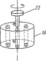
Fig. 9 represents the oblique view of the magnet of another embodiment of the present invention.
Figure 10 represents the figure of the residual misconvergence figure of YH pincushion.
Figure 11 represents the figure of the barrel-shaped residual misconvergence figure of XH.
Figure 12 represents to illustrate the figure of XH correcting circuit in the past.
Figure 13 represents the figure of electron beam the right figure of the redness of PQH.
Embodiment
Below, with reference to description of drawings the present invention is used for 46[cm] embodiment of the plane screen dish colour display tube electronic gun device of (19 inches)-100 ° of deflections.
First embodiment
Fig. 1 represents the deflection system in the colour display tube electronic gun device of first embodiment of the invention and the circuit diagram of peripheral part thereof.
The last lower coil of horizontal deflection coil 3,4 expressions connection parallel with one another.Choke coil 1 is connected in series with quadrupole coil 21, and in addition, choke coil 2 is connected in series with quadrupole coil 22.These two choke coil-quadrupole coil connectors are constituted complex correction circuit 31 by connection parallel with one another.Complex correction circuit 31 is connected in series with horizontal deflection coil 3,4.The total inductance of horizontal deflection coil 3,4 and complex correction circuit 31 is about 90[μ H].
With regard to the magnetic field of horizontal deflection coil 3,4,, weaken the pincushion field that is used for auto-convergence slightly in order to prevent the deterioration of focus characteristics.Therefore, as shown in Figure 3, under the state that does not have XH to proofread and correct, the barrel-shaped residual misconvergence of XH can produce 0.8[mm].In addition, the ordinate RB misconvergence in bight is by PQH red beam the right graphics overlay 0.5[mm], become 0.3[mm] red beam left side figure.
The left and right sides coil that frame deflector coil 5,6 expressions are connected in series mutually is respectively with damping resistance R
1, R
2Be connected in parallel.In this frame deflector coil, with coma correction coil 7, have the YH correcting circuit 9 that described YH proofreaies and correct the quadrupole coil 8 of usefulness, the vertical rectification circuit 11 that has vertical control coil 10 is connected in series.This vertical control coil 10 is made of choke coil 1,2 and saturable choke 18.The total inductance of vertical control coil 5,6, coma correction coil 7, YH correcting circuit 9 and vertical rectification circuit 11 is 5[mH].
In Fig. 1, resistance R
1=R
2=220[Ω], R
3=5.6[Ω], each diode is a Schottky diode.
Fig. 2 represent to comprise choke coil 1,2 XH, PQH, about proofread and correct the saturable choke 18 of usefulness.Choke coil the 1, the 2nd all is diameter 6[mm at front end] discoideus flanged length be 10[mm] thin bar-shaped ferrite core 12,13 on the 10 astragals footpath φ 0.2[mm that reels] three bundle copper cash constitute.Both mutual horizontally-arranged configurations, the magnetic field that produces opposite polarity.Adjacent with a flange of bar-shaped ferrite core 12,13, be used to produce the minor axis 8[mm of magnetic bias] * major diameter 14[mm] * height 24[mm] the magnet 14 of roughly long cylinder shape the S pole-face is disposed towards the flange side.Adjacent with another flange side of ferrite core 12,13, dispose vertical control coil 10.Vertical control coil 10 is the lines footpath φ 0.36[mm of 130 circles of reeling on two ends have the ferrite core 15 of the big flange of general cylindrical shape shape] coil of copper cash.
Fig. 4 represents the side view of deflection system of the present invention.Deflection system is made of horizontal deflection coil (not shown), insulation frame 17, frame deflector coil 5,6, ferrite core 16.In the barrel of neck side (electron gun side), dispose two groups of quaternate quadrupole coils that constitute by hollow molded lines circle.Wherein, one group is quadrupole coil 21 shown in Figure 1, and another group is quadrupole coil 22.As shown in Figure 5, four coils 21,22 are roughly equally spaced disposed around tubular axis.Two coils 21,22 are same shape also, are the copper cash footpaths φ 0.2[mm of 10 circles of reeling respectively] the coil of three bundle lines.Because quadrupole coil 21,22 is reeled with core shape ground mutually, so only illustrate one group four in the drawings.In addition, quadrupole coil 21,22 utilizes the magnetic field that the electric current of equidirectional in Fig. 1 circuit produces mutual opposite polarity.
In Fig. 4, on the board 41 that the rear end side of ferrite core 16 is provided with, be provided with from the coma correction coil 7,8 of clamping barrel up and down.The printed circuit board (PCB) of crossing between insulation frame 17 and the board 41 19 is terminal boards that the deflection system distribution is used.On printed circuit board (PCB) 19, saturable choke 18 is set.Saturable choke 18 as shown in Figure 2.
Below, explanation utilizes the said structure comprise saturable choke of the present invention respectively, carries out the principle that XH proofreaies and correct, PQH proofreaies and correct, side pinuchsion is proofreaied and correct.
The first, the principle that XH of the present invention proofreaies and correct is described.
If consider vertical yoke current I
V=0 situation, the vertical control coil 10 of so vertical rectification circuit 11 is not worked.At horizontal yoke current I
HDuring for half period of positive direction, the choke coil 1 when promptly left avertence is changeed structurally produces the magnetic flux Φ L1 of the last direction (hereinafter referred to as '+direction ') of figure as shown in Figure 2, and choke coil 2 has the magnetic flux Φ L2 of the following direction (being called-direction) of generation figure.The magnetic flux Φ MG of magnet 14 supply+directions.
Horizontal yoke current I
HWhen increasing, the magnetic flux Φ L1 of choke coil 1 state that reaches capacity, the inductance L 1 of choke coil 1 descends, and on the contrary, the inductance L 2 of choke coil 2 increases.Its result has the horizontal yoke current I than upper frequency composition
HMost of low choke coil 1 of inductance that flows in the choke coil 1,2 that is connected in parallel.Therefore, quadrupole coil 21 work, the quadripolar magnetic field that quadrupole coil 21 produces plays dominating role.The quadripolar magnetic field that quadrupole coil 21 produces is as shown in Figure 5 proofreaied and correct the barrel-shaped residual misconvergence of XH in phosphor screen left side.
On the contrary, when horizontal yoke current is the half period of negative direction, promptly when right avertence is changeed, choke coil 2 is saturated, mainly be quadrupole coil 22 work, quadrupole coil 22 produces the magnetic field with quadrupole coil 21 identical polars, proofreaies and correct the barrel-shaped residual misconvergence of XH on phosphor screen right side.
Fig. 6 represents vertical yoke current I
V=0 o'clock horizontal yoke current I
H(transverse axis) and the inductance L 1 of choke coil 1,2, the relation of L2 (longitudinal axis).At horizontal yoke current I
H=0 o'clock, L1=L2 is arranged, but positive direction horizontal yoke current I during the half period
HWhen increasing, L1 but descends, otherwise then, L2 increases.L1 and L2 poor (| L2-L1|) be the intensity of the quadripolar magnetic field of corrected X H.At horizontal yoke current I
HWhen increasing, because the intensity of the quadripolar magnetic field of corrected X H increases, the XH correcting value increases, so ordinate RB misconvergence on the trunnion axis in recoverable phosphor screen left side.On the contrary, in negative direction during the half period, ordinate RB misconvergence on the trunnion axis of recoverable phosphor screen right side.
The second, PQH correction principle of the present invention is described.
At vertical yoke current I
VWhen positive direction reaches maximum in the half period, when promptly utilizing the horizontal line of horizontal deflection scanning phosphor screen upper part, as shown in Figure 2, in vertical control coil 10, produce with magnet 14 opposite polarities-the magnetic flux Φ of direction
VFig. 7 represents the horizontal yoke current I of this moment
H(transverse axis) and the inductance L 1 of choke coil 1,2, the relation of L2 (longitudinal axis).The value of L1, L2 is all than vertical yoke current I
V=0 o'clock (Fig. 6) is big.Because the magnetic flux Φ of vertical control coil 10
VBe in the direction of offsetting magnet magnetic flux Φ MG, so that magnetic flux is not easy is saturated.Therefore, L1 and L2 poor (| L2-L1|) also dwindle, its result compares with the XH timing on the trunnion axis, and quadripolar magnetic field weakens.
As mentioned above, as shown in Figure 3, the ordinate RB misconvergence in phosphor screen bight is at 0.8[mm] the barrel-shaped residual misconvergence of XH on overlapping 0.5[mm] PQH red beam the right figure, 0.3[mm] the figure on the red beam left side residual.Therefore, compare with the XH timing on the trunnion axis, the ordinate misconvergence on the horizontal line on phosphor screen top is by overlapping PQH red beam the right figure in bight, and its correcting value can be less.In the invention described above, the magnetic flux that utilizes vertical control coil 10 to produce is because the quadripolar magnetic field of the ordinate misconvergence timing on the horizontal line of phosphor screen top weakens than the XH timing on the trunnion axis, so can overcorrect PQH red beam the right figure.
At vertical yoke current I
VDuring the half period, can proofread and correct PQH red beam the right figure in negative direction too.Its reason is, because vertical control coil 10 comes supplying electric current by the vertical rectification circuit 11 that uses diode as described above, produces and vertical yoke current I
VThe magnetic flux of positive direction identical polar during the half period.Its result, the quadripolar magnetic field of generation identical polar is proofreaied and correct PQH red beam the right figure equally.
The 3rd, the correction principle of side pinuchsion of the present invention is described.
Fig. 8 is expression vertical yoke current I
V=0 o'clock and vertical yoke current be I when maximum in the positive direction half period
VComparison level deflection current I during=MAX
HFigure with the relation of the total inductance L of complex correction circuit 31.If when maximum, watch the absolute value of horizontal yoke current attentively, show that so the absolute value of vertical yoke current is big more, L is big more.The magnetic flux Φ v that this means vertical control coil 10 is in the direction of the magnetic flux Φ MG that offsets magnet 14, this means under the state that described saturation characteristic weakens, because the inductance L 1 of choke coil 1,2, L2 become big, so that total inductance also becomes is big.
Utilize this effect, and compare when left end, right-hand member deflection on the trunnion axis, the total inductance of horizontal deflection system is big when the deflection of bight, therefore, the relative variation of the deflection sensitivity in bight, side pinuchsion reduces.
Second embodiment
The second embodiment of the present invention is such embodiment, structurally can change the size of magnetic flux density of the magnet 14 of saturable choke 18 shown in Figure 2, can carry out the inching of misconvergence amount between the side electron beam of ordinate on the phosphor screen trunnion axis.
Fig. 9 represents the oblique view of magnet 14.Roughly columned magnet 14 makes the S utmost point, N utmost point alternating magnetization every 90 ° around central shaft.And being provided with the central shaft is the rotation axis 23 of center rotation.By rotating this axle by hand, can change the magnetic bias intensity of choke coil shown in Figure 21,2.Thus, can carry out the fine setting of XH correcting value.
As described above, according to the present invention, even in the chromoscope of the plane screen dish that causes all performance degradation relevant easily with distortion, convergence, focusing, utilize the fairly simple device that adopts saturable choke and quadrupole coil, can keep to high-performance each performance, can obtain comprehensive high-quality chromoscope.
Claims (2)
1. colour display tube electronic gun device comprises:
The complex correction circuit, this circuit the first choke coil and first quadrupole coil be connected in series body and be connected in parallel with the body that is connected in series of the second choke coil of the described first choke coil opposite polarity and second quadrupole coil and
Vertical control coil in the described first and second choke coils, applies the magnetic bias that changes synchronously with vertical yoke current,
It is characterized in that described complex correction circuit and horizontal deflection coil are connected in series;
The intensity of the quadripolar magnetic field that described quadrupole coil produces is followed the increase of horizontal yoke current and is increased, and when vertical yoke current is maximum, compare with the magnetic field on the trunnion axis and to weaken, the total inductance of horizontal deflection system, with on the trunnion axis about hold and compare, when the deflection of bight, increase.
2. colour display tube electronic gun device as claimed in claim 1, it is characterized in that, in the described first and second choke coils, also be furnished with the magnet that applies certain magnetic bias, constitute the saturable choke by the described first and second choke coils, described vertical control coil and described magnet
During the half period of horizontal yoke current positive direction, the described first choke coil is saturated, the quadripolar magnetic field that described first quadrupole coil produces plays dominating role, during the half period of described horizontal yoke current negative direction, the described second choke coil is saturated, and the quadripolar magnetic field that described second quadrupole coil produces plays dominating role.
Applications Claiming Priority (3)
| Application Number | Priority Date | Filing Date | Title |
|---|---|---|---|
| JP197070/1999 | 1999-07-12 | ||
| JP197070/99 | 1999-07-12 | ||
| JP11197070A JP2001023541A (en) | 1999-07-12 | 1999-07-12 | Color picture tube device |
Publications (2)
| Publication Number | Publication Date |
|---|---|
| CN1280380A CN1280380A (en) | 2001-01-17 |
| CN1267960C true CN1267960C (en) | 2006-08-02 |
Family
ID=16368223
Family Applications (1)
| Application Number | Title | Priority Date | Filing Date |
|---|---|---|---|
| CNB001202286A Expired - Fee Related CN1267960C (en) | 1999-07-12 | 2000-07-12 | Colour picture tube device |
Country Status (7)
| Country | Link |
|---|---|
| US (1) | US6304044B1 (en) |
| EP (1) | EP1069763B1 (en) |
| JP (1) | JP2001023541A (en) |
| KR (1) | KR100376376B1 (en) |
| CN (1) | CN1267960C (en) |
| DE (1) | DE60035386T2 (en) |
| TW (1) | TW460895B (en) |
Families Citing this family (4)
| Publication number | Priority date | Publication date | Assignee | Title |
|---|---|---|---|---|
| JP2002025472A (en) * | 2000-06-13 | 2002-01-25 | Samsung Electro Mech Co Ltd | Electron beam deflection device and color display tube |
| US6759815B2 (en) * | 2001-09-03 | 2004-07-06 | Matsushita Electric Industrial Co., Ltd. | Color picture tube device in which YH misconvergence is corrected |
| JP2005190840A (en) * | 2003-12-25 | 2005-07-14 | Matsushita Toshiba Picture Display Co Ltd | Color picture tube device |
| US20060043867A1 (en) * | 2004-09-01 | 2006-03-02 | Matsushita Toshiba Picture Display Co., Ltd. | Color picture tube apparatus |
Family Cites Families (5)
| Publication number | Priority date | Publication date | Assignee | Title |
|---|---|---|---|---|
| US3940662A (en) * | 1974-03-14 | 1976-02-24 | Whitewater Electronics, Inc. | Saturable reactor for pincushion distortion correction |
| JPS6394542A (en) * | 1986-10-08 | 1988-04-25 | Sony Corp | Beam spot correcting device |
| US5070280A (en) * | 1989-08-25 | 1991-12-03 | Hitachi, Ltd. | Deflection yoke |
| JPH0865691A (en) * | 1994-08-19 | 1996-03-08 | Sony Corp | Deflection yoke and cathode-ray tube device |
| JP3137574B2 (en) * | 1995-11-21 | 2001-02-26 | 松下電子工業株式会社 | Image distortion correction device |
-
1999
- 1999-07-12 JP JP11197070A patent/JP2001023541A/en active Pending
-
2000
- 2000-07-08 EP EP00114734A patent/EP1069763B1/en not_active Expired - Lifetime
- 2000-07-08 DE DE60035386T patent/DE60035386T2/en not_active Expired - Fee Related
- 2000-07-11 US US09/613,324 patent/US6304044B1/en not_active Expired - Fee Related
- 2000-07-11 KR KR10-2000-0039589A patent/KR100376376B1/en not_active IP Right Cessation
- 2000-07-11 TW TW089113746A patent/TW460895B/en not_active IP Right Cessation
- 2000-07-12 CN CNB001202286A patent/CN1267960C/en not_active Expired - Fee Related
Also Published As
| Publication number | Publication date |
|---|---|
| JP2001023541A (en) | 2001-01-26 |
| EP1069763A3 (en) | 2003-10-08 |
| US6304044B1 (en) | 2001-10-16 |
| KR100376376B1 (en) | 2003-03-15 |
| DE60035386D1 (en) | 2007-08-16 |
| CN1280380A (en) | 2001-01-17 |
| TW460895B (en) | 2001-10-21 |
| KR20010015283A (en) | 2001-02-26 |
| DE60035386T2 (en) | 2007-10-31 |
| EP1069763A2 (en) | 2001-01-17 |
| EP1069763B1 (en) | 2007-07-04 |
Similar Documents
| Publication | Publication Date | Title |
|---|---|---|
| CN1140108C (en) | Misconvergence and gemetric distortion correction apparatus for deflection yoke | |
| CN1267960C (en) | Colour picture tube device | |
| CN1023043C (en) | Color cathode ray tube system with reduced spot growth | |
| CN1018873B (en) | Deflection yoke for use in colour cathode ray tube | |
| KR940011568B1 (en) | Electromagnetic deflection unit | |
| CN1059233A (en) | Deflection system with controlled beam spot | |
| US4654616A (en) | Blue bow correction for CRT raster | |
| CN1147905C (en) | Deflecting coil and winding device and winding method thereof | |
| US6573668B1 (en) | Color cathode ray tube having a convergence correction apparatus | |
| CN1097842C (en) | Apparatus for correcting raster distortion of cathod-ray tube device | |
| CN1201367C (en) | Color cathode-ray tube apparatus | |
| CN1066850C (en) | Cathod ray tube device | |
| CN1227708C (en) | Coloured cathode ray tube equipment | |
| CN1265651C (en) | Deflecting magnetic yoke device | |
| CN1315052A (en) | Color display device having quadrapole convergence coils | |
| CN1049751A (en) | Improve the chromoscope that passes aberration partially | |
| CN2847520Y (en) | Deflection coil | |
| CN1388980A (en) | Display device comprising a deflection unit, and a deflection unit for a display device | |
| CN1606865A (en) | Image-geometry corrector for a cathode-ray tube | |
| CN1581415A (en) | Color picture tube apparatus | |
| CN1755883A (en) | Color picture tube apparatus | |
| CN1664975A (en) | Deflection device for projection tube and projection tube apparatus | |
| CN1638010A (en) | Color picture tube apparatus | |
| JP2001256905A (en) | Deflecting yoke | |
| CN1267170A (en) | Deflection arrangement |
Legal Events
| Date | Code | Title | Description |
|---|---|---|---|
| C06 | Publication | ||
| PB01 | Publication | ||
| C10 | Entry into substantive examination | ||
| SE01 | Entry into force of request for substantive examination | ||
| C14 | Grant of patent or utility model | ||
| GR01 | Patent grant | ||
| C17 | Cessation of patent right | ||
| CF01 | Termination of patent right due to non-payment of annual fee |
Granted publication date: 20060802 |